Rinstrum 400 Series Quick Start Manual
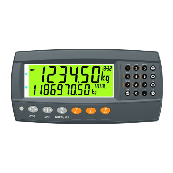
Batching indicator
Hide thumbs
Also See for 400 Series:
- Reference manual (150 pages) ,
- Quick start manual (38 pages) ,
- Operator's manual (36 pages)
Table of Contents
Advertisement
Quick Links
Advertisement
Table of Contents

Related Manuals for Rinstrum 400 Series


Summary of Contents for Rinstrum 400 Series
- Page 1 400 Series (K411) Batching Indicator Quick Start Manual 004R-615-120...
- Page 2 Rinstrum Pty Ltd. Disclaimer Rinstrum Pty Ltd reserves the right to make changes to the products contained in this manual in order to improve design, performance or reliability. The information in this manual is believed to be accurate in all respects at the time of publication, but is subject to change without notice.
-
Page 3: Table Of Contents
Quick Start - Software Version 1.x & 2.x Table of Contents 1. INTRODUCTION ................3 1.1. Manuals ................3 1.2. Shipping Contents.............3 2. SPECIFICATIONS ..............4 3. INSTALLATION .................5 3.1. Introduction ...............5 3.2. General Warnings .............5 3.3. Panel Mount Template............6 3.4. Function Keys ..............6 3.5. - Page 4 Quick Start - Software Version 1.x & 2.x 7.4. Analogue Output .............50 7.5. Communications .............50 8. HARDWARE TESTING............52 8.1. Overview .................52 8.2. Check Hardware Allocation..........52 8.3. Check Inputs ..............53 8.4. Force Outputs ..............53 8.5. Force Analogue Output...........54 8.6. Check Load Cell Hardware ..........54 9.
-
Page 5: Introduction
Quick Start - Software Version 1.x & 2.x 1. Introduction This manual contains information on the installation, calibration and setup of the indicator. 1.1. Manuals For more information on the indicator refer to the Reference Manual and Operator Manual. 1.2. Shipping Contents The following table identifies the items shipped with indicators. -
Page 6: Specifications
Quick Start - Software Version 1.x & 2.x Specifications Performance Resolution Up to 100,000 divisions, minimum of 0.25µV/division Zero Cancellation +/- 2.0mV/V Span Adjustment 0.1mV/V to 3.0mV/V Stability/Drift Zero: < 0.15µV/°C (+ 10ppm of deadload max) Span < 10 ppm/°C, Linearity < 20ppm, Noise < 0.2µVp-p Excitation 7.4 volts for up to 16 x 350 or 32 x 700 ohm load cells (4-wire or 6-wire plus shield) -
Page 7: Installation
Quick Start - Software Version 1.x & 2.x 3. Installation 3.1. Introduction The following steps are required to set up the indicator. • Inspect indicator to ensure good condition. • Use connection diagrams to wire up load cell, power and auxiliary cables as required. -
Page 8: Panel Mount Template
Quick Start - Software Version 1.x & 2.x • To avoid the possibility of electric shock or damage to the instrument, always switch off or isolate the instrument from the power supply before maintenance is carried out. 3.3. Panel Mount Template The panel mount template is supplied with the instrument. -
Page 9: Connections
Quick Start - Software Version 1.x & 2.x Connections 4.1. Cable Connections All cable connections are made to the rear of the instrument using pluggable screw terminals. It is not necessary to tin the ends of the wires with solder or to add crimp ferrules to the wires, but these techniques are compatible with the terminals. - Page 10 Quick Start - Software Version 1.x & 2.x 4.3.2. 4-Wire Connection The minimum connectivity requirements are the connection of four wires (i.e. ±Excitation and ±Signal). Internally the instrument has a precision analogue switch that can be used to connect the Sense+ and Sense– lines directly to the Excitation+ and Excitation–...
-
Page 11: Auxiliary Connections
Quick Start - Software Version 1.x & 2.x 4.3.3. 6-Wire Connection The excitation and signal lines are connected the same as for a 4-wire installation. The extra two wires (Sense + and –) should be connected to the Excitation + and – lines as close as possible to the load cell itself. - Page 12 Quick Start - Software Version 1.x & 2.x 4.4.2. Printer Connections (RXD/TXD, GND and DTR) 4.4.3. Remote Display using RS232 (TXD, GND) Refer to documentation supplied with the Remote Display for connection details. Connect RX on the Remote Display with TX on the instrument and connect the RS232 GND signals together.
-
Page 13: Connecting Shields
Quick Start - Software Version 1.x & 2.x 4.5. Connecting Shields To obtain full EMC or for RFI immunity, cable shields MUST be connected and the earth lug on the rear of the instrument must be grounded. This figure illustrates an example of possible connections. Also shown are the connecting cables restrained using cable ties fastened by screws into the rear of the unit. -
Page 14: Legal Sealing Details
Quick Start - Software Version 1.x & 2.x 4.5.1. Cable Shield Connection and Earthing • Care should be taken when connecting shields to maximise EMC or RFI immunity and minimise earth loops and cross-talk (interference) between instruments. • For full EMC or for RFI immunity, termination of the cable shields at the earth lug is very important. - Page 15 Quick Start - Software Version 1.x & 2.x 4.6.2. Lead Seals There are 2 methods of sealing the instrument with lead and wire seals: Figure 1: Lead seal on rear of instrument. Figure 2: Lead seal on boot. 004R-615-120 Page 13...
- Page 16 Quick Start - Software Version 1.x & 2.x 4.6.3. Destructible Sticker Seals There are 2 methods of sealing with destructible stickers: Figure 3: Destructible sticker seal on rear of instrument. Figure 4: Destructible sticker seal on boot. Page 14 004R-615-120...
-
Page 17: Instrument Setup
Quick Start - Software Version 1.x & 2.x 5. Instrument Setup 5.1. Accessing Full/Safe Setup When Full Setup is used, all menu items are accessible, including legal for trade and calibration sensitive settings, and care must be taken to ensure no accidental changes are made to calibration and trade settings. -
Page 18: Exiting Full Or Safe Setup
Quick Start - Software Version 1.x & 2.x 5.2. Exiting Full or Safe Setup To save settings, exit setup and return to the normal weighing mode using one of the following methods: Method 1: Press the <POWER> key. Method 2: Press the <ZERO> key repeatedly. When END displays press <TARE>. -
Page 19: Setup Menus
Quick Start - Software Version 1.x & 2.x Setup Menus 6.1. GEN.OPT (General options) DATE.F (Date format) Path Description GEN.OPT Sets the date format └ DATE.F DATE.F Values <OPT> (Default) DD.MM.YYYY DD.MM.YYYY, MM.DD.YY MM.DD.YYYY, YY.MM.DD, YYYY.MM.DD PCODE (Security passcodes) Path Description GEN.OPT Sets the instrument passcodes. - Page 20 Quick Start - Software Version 1.x & 2.x KEY.LOC (Key Function Access Control) Path Description GEN.OPT Access to each of the operator functions can be configured separately as either: └ KEY.LOC AVAIL: function always available └ P(*) └ ZERO OPER.PC: requires a valid Operator └...
- Page 21 Quick Start - Software Version 1.x & 2.x DISP (Display options) Path Description GEN.OPT These settings control the operation of the display. └ DISP └ B.LIGHT B.LIGHT (Backlight operation) └ FREQ FREQ (Frequency) display update rate. └ AUX.DSP AUX.DSP (Auxiliary Display): └...
- Page 22 Quick Start - Software Version 1.x & 2.x POWER (Power options) Path Description GEN.OPT AUT.OFF (Auto-off delay) └ POWER Sets the automatic power off setting. The └ AUT.OFF instrument will switch off after set minutes of inactivity. NEVER disables the auto power └...
-
Page 23: H.ware (Hardware Configuration & Test)
Quick Start - Software Version 1.x & 2.x 6.2. H.WARE (Hardware Configuration & Test) ALLOC (Allocation Report) Path Description H.WARE Check hardware allocation. └ ALLOC Displays the function of each item of hardware. Items of hardware include serial ports, function keys, inputs and outputs. Use the UP and DOWN arrows to step through the hardware. - Page 24 Quick Start - Software Version 1.x & 2.x SER1.HW, SER2.HW Path Description H.WARE BAUD (Baud Rate) └ SER1.HW Sets the baud rate for the port. └ BAUD PARITY └ PARITY Sets the parity for the port. └ DATA └ STOP DATA (Data bits) └...
- Page 25 Quick Start - Software Version 1.x & 2.x IO.HW Path Description H.WARE FRC.OUT (Force Outputs): used for testing and fault finding to force the IO on and off. └ IO.HW └ FRC.OUT • UP and DOWN keys to select the └...
-
Page 26: Scale (Loadcell Options And Calibration)
Quick Start - Software Version 1.x & 2.x 6.3. SCALE (Loadcell options and calibration) BUILD (Scale parameters) Path Description SCALE Scale Base configuration settings: └ BUILD TYPE: Range type └ TYPE SINGLE : Single range └ CABLE DUAL.I: Dual interval └... - Page 27 Quick Start - Software Version 1.x & 2.x OPTION (Scale options) Path Description SCALE USE (Trade Use): This setting affects the operation of trade functions. Options are: └ OPTION └ USE INDUST: Industrial (no standard) └ FILTER TRADE: Trade mode └...
- Page 28 Quick Start - Software Version 1.x & 2.x R.ENTRY Values <OPT> (Default) , On TOT.OPT Values <OPT> (Default) Disp , Gross, Net CAL (Scale calibration) Path Description SCALE Calibrate Scale └ CAL ZERO: Perform a zero calibration. └ZERO SPAN: Perform a span calibration. A zero └SPAN calibration should be done before doing a └ED.LIN...
-
Page 29: Func (Special Functions)
Quick Start - Software Version 1.x & 2.x 6.4. FUNC (Special functions) NUM (Number of special functions) Path Description FUNC Sets the number of special functions. └ NUM NUM Values <OPT> (Default) .. -8- SFn: TYPE (Function Types) Path Description FUNC Sets the function type. - Page 30 Quick Start - Software Version 1.x & 2.x SFn: KEY (Function Key / Remote Input ) Path Description FUNC Select front panel key or external input to trigger the special function. All functions └ SFn that respond to input events have a KEY └KEY setting.
- Page 31 Quick Start - Software Version 1.x & 2.x SFn: SINGLE (Single Serial Output Functions) Path Description FUNC Single serial outputs are similar to printing but do not support any interlocking or └ SFn totalising functions. └TYPE:SINGLE KEY: Function key or external input to use. └...
- Page 32 Quick Start - Software Version 1.x & 2.x SFn: START, SFn: PAUSE, SFn:ABORT, SFn PSE.ABT, SFn: SUSPND (Batching Functions) Path Description FUNC Batching control functions to start, pause or abort the batching process. └ SFn └TYPE:START, KEY: Select key or external input to use for PAUSE,ABORT, this special function.
- Page 33 Quick Start - Software Version 1.x & 2.x SFn: REM.KEY (Remote Key Functions) Path Description FUNC Remote key functions allow external inputs to be used to trigger instrument key └ SFn functions. └TYPE : REM.KEY The external ‘keys’ operate even if the └...
-
Page 34: Ser.net (Network Communications)
Quick Start - Software Version 1.x & 2.x 6.5. SER.NET (Network communications) Path Description FUNC Configure the serial networking support. └ SER.NET TYPE: Type of Network Protocol: └ TYPE NONE: Disable networking └ SERIAL Protocol B: └ ADDR TYPE Values SERIAL: Serial Port to use. -
Page 35: Ser.aut (Automatic Transmit)
Quick Start - Software Version 1.x & 2.x 6.6. SER.AUT (Automatic transmit) NUM (Number of Automatic Transmissions) Path Description SER.AUT Sets the number of special automatic outputs └ NUM Values <OPT> (Default) .. -2- AUTO.n (Automatic Output Configuration) Path Description SER.AUT These settings for AUTO.1 and AUTO.2 └... -
Page 36: Print (Printouts)
Quick Start - Software Version 1.x & 2.x 6.7. PRINT (Printouts) NUM (Number of printouts) Path Description PRINT Sets the number of printouts. └ NUM Values <OPT> (Default) .. _2_ HEADER (Print header) Path Description PRINT Sets the print header and footer. └... - Page 37 Quick Start - Software Version 1.x & 2.x Default: 0 BOTTOM: Sets the number of blank lines to add to the bottom of each page. PRINT.n … (Printout options) Path Description PRINT Each printout has its own format settings. └ PRINT.n TYPE: Sets the printout type.
-
Page 38: Setp (Setpoints)
Quick Start - Software Version 1.x & 2.x printed when a batch is aborted. CUSTOM Values <STR> SER.ST ** (Event Series Start) defines what * Active token strings is printed at the start of a series of batches. depend on the TYPE SER.END ** (Event Series End) defines setting what is printed at the end of a series of... - Page 39 Quick Start - Software Version 1.x & 2.x LGC.OR LGC.AND: active if inputs match the bits set in the mask exactly LGC.XOR OVER LGC.OR: active if any inputs match the bits set in ERROR UNDER the mask LGC.XOR: active if only one input matches the bits set in the mask PAUSE ZERO...
-
Page 40: Batch
Quick Start - Software Version 1.x & 2.x 6.9. BATCH APP (Applications) Path Description BATCH Set of predefined batching configurations for └ APP initial menu setup. The options vary the APP Values <OPT> number of materials (FILL stages) and speeds. 1MAT.1SPD, Choose an option closest to the application 1MAT.2SPD, 1MAT.3... - Page 41 Quick Start - Software Version 1.x & 2.x GEN (General) Path Description BATCH Start Interlock (ST.ILOCK): Input for start └ GEN interlock if being used (distinct from FILL └ ST.ILOCK stage interlock). If used, batch will not start └ B.ILOCK without this input active.
- Page 42 Quick Start - Software Version 1.x & 2.x PROP.TP Values <OPT> Total (TOTAL): Total batch weight. (Default) NONE , PC, PROP, Auto (AUTO): Automatically recalculate TOTAL proportion after first fill stage. TM.STRT Values Auto-clear Proportion (PROP.CL): <NUM> YES - Automatically clears proportion to 0.00…23.59 100% at the end of the batch, or the end of TM.RPT Values <NUM>...
- Page 43 Quick Start - Software Version 1.x & 2.x displayed. Tolerance Action (TOL): BEEP: beep and continue PAUSE: to pause batch, PAUSE.TOL prompt displayed Print Out (PRT.OUT): Printout to be used by the batching process. MAT (Material) Path Description BATCH Sets the name of each material to be └...
- Page 44 Quick Start - Software Version 1.x & 2.x STAGE.n:FILL Path Description Configuration of a FILL stage. BATCH Outputs – Outputs are active all the time when └ STAGES selected. └STAGE.n Slow Fill (S.FILL): Output for slow fill └TYPE : FILL Medium Fill (M.FILL): Output for medium fill if └...
- Page 45 Quick Start - Software Version 1.x & 2.x checks after a decision has been made concerning MAT Values <OPT> the outputs. For example when fast fill changes to 1..6 slow fill, or when the dump output is first turned on. ST.ACT Values <OPT>...
- Page 46 Quick Start - Software Version 1.x & 2.x STAGE.n:DUMP Path Description BATCH Hardware: └ STAGES Output (DMP.OUT): Output to by used for └ STAGE.n dump signal. └ TYPE : DUMP Stage (STG.OUT): Output to identify this └ DMP.OUT stage └ STG.OUT Tolerance (ON.TOL): Sets if dump stage └...
- Page 47 Quick Start - Software Version 1.x & 2.x set for how long the Slow Fill output is ON 0.0..18,000.0s and OFF. DLY.CHK Values <NUM> Number of jogs in a set (JOG.SET): 0.0..60,000.0s Specifies how many ‘jogs’ (Slow Fill ON then JOG.ON, JOG.OFF OFF) are performed before the instrument Values...
- Page 48 Quick Start - Software Version 1.x & 2.x STAGE.n: PULSE Path Description BATCH A stage to pulse an output where the pulse duration settable by an operator. └ STAGES └ STAGE.n NAME: 8 character string to name this └ TYPE : PULSE PULSE stage and to be displayed in the Secondary ID.
-
Page 49: Anl.out (Analogue Output)
Quick Start - Software Version 1.x & 2.x 6.10. ANL.OUT (Analogue Output) Path Description ANL.OUT Configures the operation of the analogue transmission. └ ABS ABS (Absolute Weight): Transmit negative └ SOURCE weight values the same as positive weight └ RANGE values. -
Page 50: Accessory Modules
Quick Start - Software Version 1.x & 2.x Accessory Modules 7.1. General Up to four (4) accessory modules can be plugged into the rear of the instrument to provide additional features such as: • power supply options, e.g. mains power or batteries •... -
Page 51: Input/Output Configuration
Quick Start - Software Version 1.x & 2.x 7.3. Input/Output Configuration Inputs/outputs are provided using accessory modules, such as the M4301, M4302 and M4401. Some modules provide I/O which can be inputs or outputs depending on configuration. The I/O range for each module is given in the module manual. For example, M4301 is IO1 to IO8 and M4302 is IO17 to IO20. -
Page 52: Analogue Output
Quick Start - Software Version 1.x & 2.x BATCH BATCH SETP └ STAGES └ STAGES └ NUM (1..8) └ STAGE.n └ STAGE.n └ SETPn └ TYPE : DUMP └ TYPE : PULSE └TYPE └ NAME └ DMP.OUT └OUTPUT └ PLS.OUT └... - Page 53 Quick Start - Software Version 1.x & 2.x H.WARE SER.AUT FUNC └ SER1.HW └ AUTO.n └ SER.NET └ BAUD └ TYPE └ TYPE └ PARITY └ SERIAL └ SERIAL └ DATA └ FORMAT └ ADDR └ STOP └ SOURCE └ DTR └...
-
Page 54: Hardware Testing
Quick Start - Software Version 1.x & 2.x Hardware Testing 8.1. Overview Indicator hardware can be checked using settings in the H.WARE menu. Overall hardware allocation is reviewed and clashes noted in the ALLOC menu. The status of inputs can be checked (TST.IN) and outputs forced (FRC.OUT) using items in the IO.HW menu. -
Page 55: Check Inputs
Quick Start - Software Version 1.x & 2.x IO Clashes If an item of hardware has been allocated to more than one function either a CHECK or CLASH prompt will be displayed. CHECK means that the indicator will function correctly; however, the setup is unusual and should be checked. -
Page 56: Force Analogue Output
Quick Start - Software Version 1.x & 2.x 8.5. Force Analogue Output An analogue output, voltage or current can be driven using HD.WARE:ANL.HW:FRC.OUT for testing purposes. Adjust current 4.00,4.01... 8.6. Check Load Cell Hardware The mV/V reading of the load cell can be viewed along with the number of times it has been overloaded in HD.WARE:LC.HW:MVV and OL.CNT. -
Page 57: Error Messages
Quick Start - Software Version 1.x & 2.x 9. Error Messages 9.1. Overview Error messages may be displayed to warn of operation outside of the acceptable limits. Short messages (XXXXXX) will appear as a single message. Longer messages (XXXXXX) (YYYYYY) will appear on the display in two parts, first the (XXXXXX) part, then the (YYYYYY) part. -
Page 58: Setup Errors
Quick Start - Software Version 1.x & 2.x 9.3. Setup Errors These messages show status messages or errors that may occur during the instrument setup. Error Description Resolution (ENTRY) When accessing setup, Turn the instrument (DENIED) more than three off. When the attempts have been instrument is turned made with the incorrect... -
Page 59: Calibration Errors
Quick Start - Software Version 1.x & 2.x 9.4. Calibration Errors Following are a list of the possible error messages that may be displayed to warn of failed or incorrect calibration: Error Description Resolution (FAILED) An attempt has been Check weights and (BAND) made to calibrate with a retry. -
Page 60: Pause Conditions
Quick Start - Software Version 1.x & 2.x 9.5. Pause Conditions The following table lists the possible pause messages that may be displayed due to the condition noted. Pause Msg Description Resolution "OPER" Operator pause via function Press Start when ready "OLOAD", Paused due to an overload... -
Page 61: Diagnostic Errors
Quick Start - Software Version 1.x & 2.x 9.6. Diagnostic Errors The instrument continually monitors the condition of the internal circuits. Any faults or out-of-tolerance conditions are shown on the display as an E type error message. Error Description Resolution (E0001) The power supply voltage Check supply is too low. - Page 62 Quick Start - Software Version 1.x & 2.x Notes Page 60 004R-615-120...
- Page 63 Notes...
Need help?
Do you have a question about the 400 Series and is the answer not in the manual?
Questions and answers