Rinstrum 400 Series Operator's Manual
Digital indicator
Hide thumbs
Also See for 400 Series:
- Reference manual (150 pages) ,
- Quick start manual (64 pages) ,
- Operator's manual (28 pages)

Related Manuals for Rinstrum 400 Series


Summary of Contents for Rinstrum 400 Series
- Page 1 400 Series (K401, K402, K403, K491) Digital Indicator Operator Manual RI00-605-130...
- Page 2 Rinstrum Pty Ltd. Disclaimer Rinstrum Pty Ltd reserves the right to make changes to the products contained in this manual in order to improve design, performance or reliability. The information in this manual is believed to be accurate in all respects at the time of publication, but is subject to change without notice.
-
Page 3: Table Of Contents
Operator Manual - Software Version 1.x & 2.x Table of Contents 1. INTRODUCTION..............3 2. SAFETY ................4 2.1. Operating Environment ..........4 2.2. Electrical Safety ............4 2.3. Cleaning ..............4 3. BASIC OPERATION............5 3.1. User Interface Display and Controls ......5 3.2. Basic Operation............9 3.3. - Page 4 Operator Manual - Software Version 1.x & 2.x 5.12. Semi.PT ..............30 6. ERROR MESSAGES ............31 Weighing Errors ..............31 Page 2 004R-601-170...
-
Page 5: Introduction
Operator Manual - Software Version 1.x & 2.x 1. Introduction This instrument is a precision digital indicator using the latest Sigma-Delta A/D technology to ensure fast and accurate weight readings. Zero and Tare functionality as well as Alibi mode, pluggable modules and battery backed clock/calendar, special function keys (for counting, unit switching, peak-hold, etc). -
Page 6: Safety
Operator Manual - Software Version 1.x & 2.x 2. Safety 2.1. Operating Environment • Operating Temperature: –10 to 50°C • Humidity: <90% non-condensing • Operating Voltage: Shown on Rear Label 2.2. Electrical Safety • For your protection all mains electrical hardware must be rated to the environmental conditions of use. -
Page 7: Basic Operation
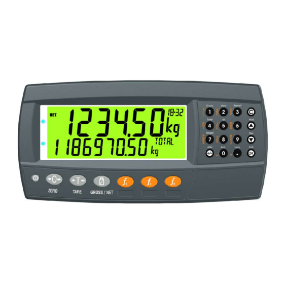
Operator Manual - Software Version 1.x & 2.x 3. Basic Operation 3.1. User Interface Display and Controls Overview Code Description Display Numeric Keypad Function Keys (user defined) Function Keys (Fixed) Power Key Page 5 004R-601-170... - Page 8 Operator Manual - Software Version 1.x & 2.x Display Code Description Primary Annunciators Primary Display Auxiliary Display Primary Units Secondary ID Miscellaneous Annunciators Secondary Units Secondary Display Page 6 004R-601-170...
- Page 9 Operator Manual - Software Version 1.x & 2.x Primary Annunciators Symbol Name Description Visible when the displayed reading is HOLD held. Visible when the displayed reading represents Net weight. Visible when the gross reading is within ± ZERO ¼ of a division of true zero. Visible when the displayed reading is not MOTION stable.
- Page 10 Operator Manual - Software Version 1.x & 2.x Keypad Code Description Numeric Button White Characters Additional Functions (Hold 2 seconds) Orange (Alpha and Symbols) Characters Cancel Undo last command; step backwards (including in menus). Move cursor backwards; previous option Down Move cursor forwards;...
-
Page 11: Basic Operation
Operator Manual - Software Version 1.x & 2.x 3.2. Basic Operation Power Key ON Instrument OFF Instrument Zero Key Page 9 004R-601-170... - Page 12 Operator Manual - Software Version 1.x & 2.x Tare Key Preset Tare Setting Preset Tare Page 10 004R-601-170...
- Page 13 Operator Manual - Software Version 1.x & 2.x Displaying Preset Tare Gross/Net Key Page 11 004R-601-170...
-
Page 14: Stability Considerations
Operator Manual - Software Version 1.x & 2.x 3.3. Stability Considerations Some functions (E.g. Tare and Zero) require a stable weight. These functions will wait for up to 10 seconds for stable weight. 3.4. Security Most functions can be locked in setup. The locking options are: •... -
Page 15: Additional Functions
Operator Manual - Software Version 1.x & 2.x 4. Additional Functions 4.1. Product Selection 4.2. Add Product Page 13 004R-601-170... -
Page 16: Delete Product
Operator Manual - Software Version 1.x & 2.x 4.3. Delete Product 4.4. Rename Product 4.5. Clock Page 14 004R-601-170... -
Page 17: View
Operator Manual - Software Version 1.x & 2.x 4.6. View 4.7. Report Page 15 004R-601-170... -
Page 18: Totals
Operator Manual - Software Version 1.x & 2.x 4.8. Totals 4.9. IDs Page 16 004R-601-170... -
Page 19: Targets
Operator Manual - Software Version 1.x & 2.x 4.10. Targets 4.11. Lock Page 17 004R-601-170... -
Page 20: Alibi
Operator Manual - Software Version 1.x & 2.x 4.12. Alibi Switching to Alibi Mode Returning from Alibi Mode Page 18 004R-601-170... -
Page 21: Acc
Operator Manual - Software Version 1.x & 2.x Viewing DSD records in Alibi mode 4.13. All Modules M4221 Ethernet Module Page 19 004R-601-170... -
Page 22: Function Keys
Operator Manual - Software Version 1.x & 2.x 5. Function Keys 5.1. Introduction The instrument has 3 function keys. External keys can also be used. The function of the keys can be configured to any of the functions detailed below 5.2. -
Page 23: Single
Operator Manual - Software Version 1.x & 2.x 5.3. Single 5.4. Test Page 21 004R-601-170... -
Page 24: Count
Operator Manual - Software Version 1.x & 2.x 5.5. Count Counts the number of items on the scale based on a sample. Short Press: Switch between weight and pieces Long Press: Change sample size and weight Page 22 004R-601-170... -
Page 25: Piece
Operator Manual - Software Version 1.x & 2.x 5.6. Piece Counts the number of items on the scale based on piece weight. Short Press: Switch between weight and pieces Long Press: Enter piece weight Page 23 004R-601-170... -
Page 26: Units
Operator Manual - Software Version 1.x & 2.x 5.7. Units Convert primary (calibrated) units to alternative units. Short Press: Switch between primary and alternative units Long Press: Enter conversion factor for custom units Page 24 004R-601-170... -
Page 27: Hold
Operator Manual - Software Version 1.x & 2.x 5.8. Hold Manual hold Hold Release Page 25 004R-601-170... -
Page 28: Peak Hold
Operator Manual - Software Version 1.x & 2.x 5.9. Peak Hold Capture peak weight. Short Press: Switch between weight and peak weight Long Press: Clear peak values Page 26 004R-601-170... - Page 29 Operator Manual - Software Version 1.x & 2.x Peak hold process Page 27 004R-601-170...
-
Page 30: Prd.sel
Operator Manual - Software Version 1.x & 2.x 5.10. Prd.Sel Product Select. Short Press: Cycles the display of available totals for the current product Long Press: Select product by number Page 28 004R-601-170... -
Page 31: Hi.res
Operator Manual - Software Version 1.x & 2.x 5.11. Hi.Res High resolution mode toggle. Short press – Industrial Mode Display high resolution reading, until function key pressed again. Short press – Trade Mode Display high resolution reading for five (5) seconds, then return to original state. Page 29 004R-601-170... - Page 32 Operator Manual - Software Version 1.x & 2.x 5.12. Semi.PT Perform semi-automatic preset tare. Preset tare value is stored on a per product basis. Page 30 004R-601-170...
- Page 33 Operator Manual - Software Version 1.x & 2.x 6. Error Messages Weighing Errors These messages show status messages or errors that may occur during normal weighing operation. Error Description Resolution U.LOAD The weight is below the Increase the weight minimum allowable or decrease the weight reading.
- Page 34 Operator Manual - Software Version 1.x & 2.x Notes: Page 32 004R-601-170...
- Page 35 Diagnostic Errors The instrument continually monitors the condition of the internal circuits. Any faults or out-of-tolerance conditions are shown on the display as an E type error message. Error Description Resolution E0001 The power supply voltage Check supply is too low. E0002 The power supply voltage Check scale / cables...
Need help?
Do you have a question about the 400 Series and is the answer not in the manual?
Questions and answers