Table of Contents
Advertisement
Quick Links
Advertisement
Table of Contents

Related Manuals for Rinstrum K405


Summary of Contents for Rinstrum K405
- Page 1 400 Series (K404, K405, K422) Digital Indicator Reference Manual...
- Page 3 (electronic, mechanical, photocopying, recording or otherwise) whatsoever without prior written permission of Rinstrum Pty Ltd. Disclaimer Rinstrum Pty Ltd reserves the right to make changes to the products contained in this manual in order to improve design, performance or reliability.
-
Page 4: Table Of Contents
INTRODUCTION ........................6 1.1. Overview ........................6 1.2. The Manuals Set ......................7 1.3. Document Conventions ....................7 1.4. Software Comparison K404, K405 and K422 ............... 7 2. SPECIFICATIONS ........................8 3. INSTALLATION ........................9 3.1. Introduction ........................9 3.2. ... - Page 5 Two Pass ........................45 8.7. Two Pass – Automatic Temporary ID Allocated ............45 9. TRUCK WEIGHING OPERATION-STATIC AXLE (K405) ............. 46 9.1. Print Current Weight of Truck ..................46 9.2. Single Pass - Permanent Truck ID with Preset Tare ........... 46 ...
- Page 6 12.8. SETP (Setpoints) ......................77 12.8.1. NUM (Number of setpoints) ................ 77 12.8.2. SETP1 … SETP8 (K422 only) /SETP16 (K404 and K405) (Setpoint options) ....77 12.9. AXLE (K405) ....................... 80 12.9.1. MIN.WGT (Minimum weight) ............... 80 Page 3 004R-646-113...
- Page 7 14.2.5. Calibrating an instrument over a network ........... 93 14.3. Network Protocol SIMPLE ................... 94 14.4. Network Protocol BARCODE (K404 and K405 only) ..........95 14.5. Network Protocol LUA BUFFER (K422 only) .............. 95 14.6. rinCMD Examples ....................... 96 15. AUTOMATIC WEIGHT OUTPUT ................... 98 ...
- Page 8 22. APPENDIX 5: ERROR MESSAGES ..................135 22.1. Overview ........................135 22.2. Weighing Errors ......................135 22.3. Axle Weighing Errors (K405 and K422) ..............135 22.4. Setup Errors ......................136 22.5. Diagnostic Errors ....................... 136 23. APPENDIX 6: M4221 ETHERNET MODULE ..............138 ...
-
Page 9: Introduction
Reference Manual Rev 1.13 1. Introduction 1.1. Overview This precision digital indicator uses the latest Sigma-Delta A/D technology to ensure fast and accurate weight readings. The setup and calibration of the instrument are digital, with a non-volatile security store for all setup parameters. It may be operated from either a DC power source (12V to 24V ) or AC power... -
Page 10: The Manuals Set
Setup and is trade critical. When trade critical settings are changed the calibration counter is incremented. Table 1: Document Conventions 1.4. Software Comparison K404, K405 and K422 The table below only lists the features that vary between each version of the K404, K405, and K422 software. Feature... -
Page 11: Specifications
Reference Manual Rev 1.13 2. Specifications Performance Resolution Up to 100,000 divisions, minimum of 0.25V/division Zero Cancellation 2.0mV/V Span Adjustment 0.1mV/V to 3.0mV/V Stability/Drift Zero: < 0.1V/C (+ 8ppm of deadload max) Span < 8 ppm/C, Linearity < 20ppm, Noise < 0.2Vp-p Excitation 7.4 volts for up to 16 x 350 or 32 x 700 ohm load cells (4-wire or 6-wire plus shield) -
Page 12: Installation
Reference Manual Rev 1.13 3. Installation 3.1. Introduction The following steps are required to set up the indicator. Inspect indicator to ensure good condition. Use connection diagrams to wire up load cell, power and auxiliary cables as required. ... -
Page 13: Dc Power (Dc Pwr + , Dc Pwr -)
Reference Manual Rev 1.13 Figure 2: Cable Connections 3.7. DC Power (DC PWR + , DC PWR –) The DC supply need not be regulated, provided that it is free of excessive electrical noise and sudden transients. The instrument can be operated from a high quality plug-pack as long as there is sufficient capacity to drive both it and the load cells. -
Page 14: 6-Wire Connection
Reference Manual Rev 1.13 Figure 3: 4-Wire Connections 3.8.3. 6-Wire Connection The excitation and signal lines are connected the same as for a 4-wire installation. The extra two wires (Sense + and –) should be connected to the Excitation + and – lines as close as possible to the load cell itself. -
Page 15: Serial
Reference Manual Rev 1.13 3.9.1. RS-232 Serial Direct Personal Computer Link (RX, TX, GND) Figure 5: RS-232 - Instrument to PC using COM Port (DB9) Printer Connections (TX, DTR and GND) Figure 6: RS-232 – Instrument to Printer (DB25) ... - Page 16 Reference Manual Rev 1.13 When operating in a Ring Network, the Instruments must have: same serial port options, i.e., baud, parity, data bits, stop bits; unique addresses. Figure 7: RS-232 Short Cable Runs (Ring Network using COM Port) Page 13 004R-646-113...
-
Page 17: Serial
Reference Manual Rev 1.13 Figure 8: RS-232 Long Cable Runs (Ring Network using COM Port) 3.9.2. RS-485 Serial Remote Display (TA, TB) RS485 is recommended for communicating over distances longer than a few metres. Connect TA to RA and TB to RB on the remote display. 3.10. -
Page 18: Connecting Shields
Reference Manual Rev 1.13 Figure 9: Optical Communications attachment 3.11. Connecting Shields To obtain full EMC or for RFI immunity, cable shields MUST be connected and the earth lug on the rear of the instrument must be grounded. Figure 10 illustrates an example of possible connections. Also shown are the connecting cables restrained using cable ties fastened by screws into the rear of the unit. -
Page 19: Cable Shield Connection And Earthing
Reference Manual Rev 1.13 Figure 10: Cable Shield Connection 3.11.1. Cable Shield Connection and Earthing Care should be taken when connecting shields to maximise EMC or RFI immunity and minimise earth loops and cross-talk (interference) between instruments. For full EMC or for RFI immunity, termination of the cable shields to the connectors is very important. -
Page 20: Accessory Module Connection
Reference Manual Rev 1.13 proper sealing procedures be adhered to. Refer to Trade Label page 115, Lead Seals page 115, Destructible Sticker Seals page 115 and Electronic Seal page 115 sections for more information. 3.13. Accessory Module connection Up to 4 accessory modules can be plugged into the rear of the instrument. There are many types of modules which can be used. -
Page 21: Setup Menus
Reference Manual Rev 1.13 4. Setup Menus Throughout the setup menus different data entry methods are used. Each method is described below. 4.1. Accessing Setup Menus There are two methods to access the Setup area: The Full Setup method provides access to all functions in Setup, including legal for trade and calibration sensitive settings. -
Page 22: Setup Display Prompts
Reference Manual Rev 1.13 4.1.1. Setup Display Prompts When accessing Full or Safe Setup the instrument will beep twice and enter the Setup Menus. If a passcode has been configured, the P.CODE prompt will display and the correct passcode must be entered to continue. Refer to Passcodes page 53 for more information. -
Page 23: Changing Data
Reference Manual Rev 1.13 Code Description Parent Menu Item Name Menu Level Item Data - If this is blank then the Item is a sub-menu. 4.4. Changing Data Menu items containing data are shown along with their data (strings may show the first few characters only). -
Page 24: Selections And Options
Reference Manual Rev 1.13 4.6. Selections and Options A selection entry requires the choice of a single option from a list. Using the up and down arrows, select the desired option and press the OK key. Example: When in Setup follow the steps below to set Scale:Build:Cable. Press <ZERO>... -
Page 25: Numerical String Editing
Reference Manual Rev 1.13 4.7.2. Numerical String Editing Numerical string editing is useful when entering strings containing only numbers. The available characters are the numbers and the decimal point. Special keys are: <OK>: Accept changes and finish. <Long press of cancel>: Cancel and exit without changes ... -
Page 26: Basic Operation
Reference Manual Rev 1.13 5. Basic Operation 5.1. User Interface Display and Controls 5.1.1. Overview Code Description Display Numeric Keypad Function Keys (user defined) Function Keys (Fixed) Power Key Page 23 004R-646-113... -
Page 27: Display
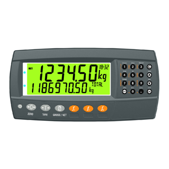
Reference Manual Rev 1.13 5.1.2. Display Code Description Primary Annunciators Primary Display Auxiliary Display Primary Units Secondary ID Eg Product Name = CONCRETE in example above. Miscellaneous Annunciators Secondary Units Secondary Display 5.1.3. Primary Annunciators Symbol Name Description Visible when the displayed reading is held. HOLD Visible when the displayed reading represents Net weight. -
Page 28: Keypad
Reference Manual Rev 1.13 5.1.4. Keypad Code Description Numeric Button White Characters Hold 2 seconds Orange Characters (Alpha and Symbols) Cancel Undo last command; step backwards (including in setup menus). Move cursor backwards; previous option Down Move cursor forwards; next option Accept this choice Decimal Point Place decimal point... -
Page 29: Operation Keys
Reference Manual Rev 1.13 5.2. Operation Keys 5.2.1. Turn Instrument ON - Short press <Power> 5.2.2. Turn Instrument OFF - Long press <Power> 5.2.3. Additional Power Information Power Key Locked: If the power key is locked, the Instrument cannot be turned off from the front keypad. -
Page 30: Tare Key
Reference Manual Rev 1.13 5.4. Tare Key This key is used to temporarily set the scale to zero. The display will show the Net weight and the NET annunciator will be lit. The weight tared is deducted from the allowable range of the scale, reducing the maximum weight that can be displayed. -
Page 31: Gross/Net Key
Reference Manual Rev 1.13 5.4.3. Gross/Net Key This key toggles the weight display between the Gross weight and the Net weight (provided that a Tare has previously been acquired using the <TARE> key). If a preset Tare has been entered, the value of the preset Tare will be temporarily displayed when switching from Gross to Net display. -
Page 32: Print Key
When docket printing, a long press ends the docket. Short press 5.6.2. PRINT (K405 and K422) A Print key can be used to skip the IDLE wait and print the truck total. 5.7. - Page 33 Reference Manual Rev 1.13 Long press A long press allows the units conversion factor to be entered. If lb/kg switching is chosen, this will be unavailable. Function key 3 and external keys are programmable. Refer 7 Special Functions and External Keys page38 for other available functions.
-
Page 34: Clock
Reference Manual Rev 1.13 5.8. Clock A long press of the 1 key (Clock) allows the system time and date to be viewed and changed 5.9. Report A long press of the 3 key (Report) allows reports to be printed. Page 31 004R-646-113... -
Page 35: Total
Reference Manual Rev 1.13 5.10. Total A long press of the 4 key (Total) allows totals to be viewed and cleared. 5.11. User ID A long press of the 5 key (ID) allows User IDs to be viewed and cleared. The Settable Consecutive Print ID can also be viewed and edited, refer also to 16.2 Print ID page 100. -
Page 36: Target
Reference Manual Rev 1.13 5.12. Target A long press of the 7 key (Target) allows setpoint targets to be viewed and changed. 5.13. Lock A long press of the . key (Lock) allows instrument to be locked. The instrument can be unlocked by entering the operator passcode when prompted. -
Page 37: Alibi
Reference Manual Rev 1.13 5.14. Alibi A long press of the +/- key (Alibi) will switch the instrument to Alibi mode. Alibi mode is used to verify scale readings. To return from Alibi mode, long press the +/- key (Alibi) again. 5.14.1. -
Page 38: Acc
Reference Manual Rev 1.13 5.15. Acc A long press of the 0 key (Acc) is used to view information about the attached accessory modules. When a M4221 Ethernet module is attached, the current IP (Internet Protocol) settings can be viewed from the Acc menu. The “.” key allows the second half of longer IP addresses to be displayed. -
Page 39: Select/Add/Delete Truck Ids
Reference Manual Rev 1.13 6. Select/Add/Delete Truck IDs 6.1.1. Select a Truck ID - Short Press of Up and Down keys A short press of the up and down arrow keys will allow the user to select the desired truck from a list of the most recently used. The keypad can be used to enter the first letter of the truck name. -
Page 40: Delete A Truck Id - Long Press Of The Down Key (Del)
Reference Manual Rev 1.13 6.1.4. Delete a Truck ID - Long Press of the Down Key (Del) A long press of this key allows the user to delete a truck. Trucks can only be deleted if the total weight is 0. Truck totals can be cleared using a long press of the 4 key (Total). -
Page 41: Special Functions And External Keys
The instrument has three (3) special function keys on the front panel, the K404, K405 and K422 have F1 set to the Truck key and F2 as a Print key. Functions are set in the FUNC menu, labels are provided that can be applied depending on what function is assigned. -
Page 42: Units
Reference Manual Rev 1.13 7.5. UNITS The units key is used to convert primary (calibrated) units to alternative units. Short press A short press switches between primary and alternative units. Long press A long press allows the units conversion factor to be entered. If lb/kg switching is chosen, this will be unavailable. -
Page 43: Hold
Reference Manual Rev 1.13 7.6. HOLD A hold key performs a manual hold. Pressing the hold key again will cancel the hold. Hold Release 7.7. HI.RES A short press of the high resolution button will enable or disable high resolution mode. -
Page 44: Sc.exit
Reference Manual Rev 1.13 Short press – Trade Mode Display high resolution reading for five (5) seconds, then return to original state. 7.8. SC.EXIT A short press of the scale exit button will trigger the scale exit setpoint if the weight is outside of the zero band. -
Page 45: Truck Weighing Operation-Static (K404)
Reference Manual Rev 1.13 8. Truck Weighing Operation-Static (K404) 8.1. Static Truck Weighing Summary 8.1.1. Weighing in Once a Truck ID with no first weight or preset tare has been selected the indicator will move to weigh in mode. When the truck is on the scale you can either press the OK key to store the current weight as the first weight, press the print key to print the current weight... -
Page 46: Print Current Weight Of Truck
Reference Manual Rev 1.13 8.2. Print Current Weight of Truck 8.3. Single Pass - Permanent Truck ID with Preset Tare Page 43 004R-646-113... -
Page 47: Single Pass - Temporary Id (Operator Entered) With A Preset Tare
Reference Manual Rev 1.13 8.4. Single Pass - Temporary ID (Operator Entered) with a Preset Tare 8.5. Single Pass – Automatic Temporary ID Allocated with a Preset Tare Page 44 004R-646-113... -
Page 48: Two Pass
Reference Manual Rev 1.13 8.6. Two Pass 8.7. Two Pass – Automatic Temporary ID Allocated Page 45 004R-646-113... -
Page 49: Truck Weighing Operation-Static Axle (K405)
Reference Manual Rev 1.13 9. Truck Weighing Operation-Static Axle (K405) 9.1. Print Current Weight of Truck 9.2. Single Pass - Permanent Truck ID with Preset Tare Page 46 004R-646-113... -
Page 50: Single Pass - Temporary Id (Operator Entered) With A Preset Tare
Reference Manual Rev 1.13 9.3. Single Pass - Temporary ID (Operator Entered) with a Preset Tare 9.4. Single Pass – Automatic Temporary ID Allocated with a Preset Tare Page 47 004R-646-113... -
Page 51: Two Pass
Reference Manual Rev 1.13 9.5. Two Pass 9.6. Two Pass – Automatic Temporary ID Allocated Page 48 004R-646-113... -
Page 52: Truck Weighing Operation-Dynamic Axle (K422)
Reference Manual Rev 1.13 10. Truck Weighing Operation-Dynamic Axle (K422) 10.1. Print Current Weight of Truck 10.2. Single Pass - Permanent Truck ID with Preset Tare Page 49 004R-646-113... -
Page 53: Single Pass - Temporary Id (Operator Entered) With A Preset Tare
Reference Manual Rev 1.13 10.3. Single Pass - Temporary ID (Operator Entered) with a Preset Tare 10.4. Single Pass – Automatic Temporary ID Allocated with a Preset Tare Page 50 004R-646-113... -
Page 54: Two Pass
Reference Manual Rev 1.13 10.5. Two Pass 10.6. Two Pass – Automatic Temporary ID Allocated Page 51 004R-646-113... -
Page 55: Configuration
Reference Manual Rev 1.13 11. Configuration 11.1. General Setup Information Configuration and calibration can be performed entirely from the front panel, using the digital setup facility. When Full Setup is used, all menu items are accessible and care must be taken to ensure no accidental changes are made to calibration and trade settings. -
Page 56: Industrial Vs Trade Modes
Reference Manual Rev 1.13 11.4. Industrial vs Trade Modes The instrument may be operated in Industrial or Trade modes. These modes restrict certain aspects of the operation of the instrument to ensure compliance with trade certified standards. The following table lists the operation differences for each of these modes. Element Industrial Trade... -
Page 57: Full Setup Passcode
Reference Manual Rev 1.13 11.6.1. Full Setup Passcode Setting a passcode for Full Setup restricts access to Full Setup. 11.6.2. Safe Setup Passcode Setting a passcode for Safe Setup restricts access to Safe Setup functions. In addition, front panel functions can be configured to prompt for a Safe Setup passcode before operating. -
Page 58: Setup Menus
Reference Manual Rev 1.13 12. Setup Menus 12.1. GEN.OPT (General options) 12.1.1. LANG (Operator language) Path Description GEN.OPT Sets the operator language. └ LANG NB: Setup menus are fixed in English. LANG Values <OPT> English (Default) German Dutch ... -
Page 59: Key.loc (Key Function Access Control)
Reference Manual Rev 1.13 12.1.4. KEY.LOC (Key Function Access Control) Path Description GEN.OPT Access to each of the operator functions can be └ KEY.LOC configured separately. └ P(*) The options are: └ ZERO AVAIL: function always available └ TARE OPER.PC: requires a valid Operator Passcode └... -
Page 60: Id.name (User Defined Strings)
Reference Manual Rev 1.13 12.1.6. ID.NAME (User Defined Strings) Path Description GEN.OPT There are five User Strings available to the operator └ ID.NAME when the ‘5’ key is pressed for 2 seconds (function └ NAME.1 ‘ID’). └ NAME.2 NAME.1, NAME.2, NAME.3, NAME.4 and NAME.5 └... - Page 61 Reference Manual Rev 1.13 Values This will not affect settings in the SCALE menu which includes all calibration and configuration DEFAULT? <OK> settings. CONFIRM? <OK> Page 58 004R-646-113...
-
Page 62: H.ware (Hardware Configuration & Test)
Reference Manual Rev 1.13 12.2. H.WARE (Hardware Configuration & Test) 12.2.1. LC.HW Path Description H.WARE └ LC.HW View Loadcell mV/V reading. └ MVV OL.CNT (Overload count) └ OL.CNT └ OL.CLR Shows the number of times the instrument has been overloaded or underloaded by at least 50% of fullscale. -
Page 63: Ser1.Hw, Ser2.Hw
Reference Manual Rev 1.13 12.2.2. SER1.HW, SER2.HW Path Description H.WARE BAUD (Baud Rate) └ SER1.HW Sets the baud rate for the port. └ BAUD PARITY └ PARITY └ DATA Sets the parity for the port. └ STOP DATA (Data bits) └... -
Page 64: Eth.hw
Reference Manual Rev 1.13 12.2.3. ETH.HW Path Description H.WARE DHCP (Dynamic Host Configuration Protocol) └ ETH.HW Enables or disables the use of DHCP to configure └ DHCP the IP settings of the M4221 Ethernet module. To └ IP use this option requires a DHCP server on the └... -
Page 65: Io.hw
Reference Manual Rev 1.13 12.2.5. IO.HW Path Description H.WARE FRC.OUT (Force Outputs) └ IO.HW Use this when testing and fault finding to force the └ FRC.OUT IO on and off. Use the UP and DOWN keys to └ TST.IN select the output. Use the +/- key to switch the └... -
Page 66: Scale (Loadcell Options And Calibration)
Reference Manual Rev 1.13 12.3. SCALE (Loadcell options and calibration) 12.3.1. BUILD (Scale parameters) Path Description SCALE Scale Base configuration settings: └ BUILD TYPE: Range type. Options are: └ TYPE () SINGLE : Single range └ CABLE () DUAL.I: Dual interval () └... -
Page 67: Option (Scale Options)
Reference Manual Rev 1.13 12.3.2. OPTION (Scale options) Path Description SCALE USE (Trade Use): This setting affects the └ OPTION operation of trade functions. Options are: INDUST: Industrial (no standard) └ USE () OIML: OIML trade mode └ FILTER () ... -
Page 68: Cal (Scale Calibration)
Reference Manual Rev 1.13 12.3.3. CAL (Scale calibration) Path Description SCALE Calibrate Scale └ CAL ZERO: Perform a zero calibration. () └ZERO SPAN: Perform a span calibration. A zero () └SPAN calibration should be done before doing a span () └ED.LIN calibration. -
Page 69: Func (Special Functions)
Reference Manual Rev 1.13 12.4. FUNC (Special functions) The instrument supports up to eight special functions. Enter the number of special functions to use and configure each one according to the function type required. Most functions need only to be associated with a key or input to function but some have additional configuration settings as detailed below. -
Page 70: Sfn: Key (Function Key / Remote Input)
Reference Manual Rev 1.13 12.4.3. SFn: KEY (Function Key / Remote Input) Path Description FUNC Select front panel key or external input to trigger the └ SFn special function. All functions that respond to input events have a KEY setting. └KEY F1 and F2 are permanently assigned to Truck KEY Values... -
Page 71: Sfn: Single (Single Serial Output Functions)
Reference Manual Rev 1.13 12.4.5. SFn: SINGLE (Single Serial Output Functions) Path Description FUNC Single serial outputs are similar to printing but do └ SFn not support any interlocking or totalising functions. └TYPE : SINGLE KEY: Function key or external input to use. └... -
Page 72: Sfn: Units (Unit Switching Functions)
Reference Manual Rev 1.13 12.4.7. SFn: UNITS (Unit Switching Functions) Path Description FUNC Unit Switching enables the display and printing of └ SFn alternative units to those used for the primary calibration of the instrument. └TYPE : UNITS └ KEY KEY: Select key or external input to use. -
Page 73: Sfn: Rem.key (Remote Key Functions)
Reference Manual Rev 1.13 12.4.9. SFn: REM.KEY (Remote Key Functions) Path Description FUNC Remote key functions allow external inputs to be └ SFn used to trigger instrument key functions. └TYPE : REM.KEY The external ‘keys’ operate even if the instrument └... -
Page 74: Sfn: Sc.exit (Scale Exit)
Reference Manual Rev 1.13 12.4.12. SFn: SC.EXIT (Scale Exit) Path Description FUNC Key/input to trigger scale exit (SC.EXIT) setpoint. └ SFn KEY: Select key or external input to use. └ TYPE : SC.EXIT └ KEY KEY Values <OPT> None (Default) , F1 .. -
Page 75: Ser.net
SIMPLE: See Network Communications page TYPE Values <OPT> (Default) NONE, RINCMD BARCODE (K404 and K405 only): Use a SIMPLE, BARCODE, LUA barcode reader for truck selection. BUFFER LUA BUFFER (K422 only): Buffer all comms for Lua module to read. -
Page 76: Ser.aut (Automatic Transmit)
Reference Manual Rev 1.13 12.6. SER.AUT (Automatic transmit) 12.6.1. NUM (Number of Automatic Transmissions) Path Description SER.AUT Sets the number of special automatic outputs └ NUM Values <OPT> (Default) .. -2- 12.6.2. AUTO.n (Automatic Output Configuration) Path Description SER.AUT These settings are the same for AUTO.1 and └... -
Page 77: Print (Printouts)
Reference Manual Rev 1.13 12.7. PRINT (Printouts) 12.7.1. NUM (Number of printouts) Path Description PRINT Sets the number of printouts. └ NUM Values <OPT> (Default) .. _2_ 12.7.2. HEADER (Print header) Path Description PRINT Sets the print docket header. └ HEADER Values <STR>... -
Page 78: Space (Print Blank Space Options)
CUSTOM EV.AXLE (K405 and K422 only) defines the SERIAL Values string to be printed for each axle. <OPT> (Default) ABORT (K405 and K422 only) defines the string SER1A , SER2A, SER3A to be printed if weighing aborted. Page 75 004R-646-113... - Page 79 Reference Manual Rev 1.13 NAME Values EV.GRP (K422 only) defines the string to be <STR> printed for each axle group. 6 character String REPORT: CUSTOM Values <STR> REP.ST (Report Start) defines start of report. Active token strings depend on the TYPE setting REP.PR (Report Product) controls the information printed for each product.
-
Page 80: Setp (Setpoints)
NUM (Number of setpoints) Path Description SETP Sets the number of special setpoints └ NUM Values <OPT> (Default) .. _8_ (K422) (K404 and K405) _16_ 12.8.2. SETP1 … SETP8 (K422 only) /SETP16 (K404 and K405) (Setpoint options) Path Description SETP Configure the operation of each setpoint. - Page 81 0.040s (****) NB: Only for PULSE LATCH: Setpoint output is latched. TIMING setpoint. RESET(K404 and K405 only): Select which IO is RDY.TIM Values <NUM> used as an input to disable the setpoint. Options are 0.000 to 60.000 s NONE, IO1..IO32 Default: 0.000s...
- Page 82 Reference Manual Rev 1.13 PLS.NUM Values DLY.ON: Delay for logic setpoints before setpoint <NUM> becomes active. 1 to 20 Default 1 (****) NB: Only for PULSE HLD.OFF: Delay for logic setpoints before setpoint TIMING setpoint. becomes inactive. RST.LGC Values <OPT> NAME: Give the setpoint a name, this will be shown HIGH (Default)
-
Page 83: Axle (K405)
Reference Manual Rev 1.13 12.9. AXLE (K405) 12.9.1. MIN.WGT (Minimum weight) Path Description AXLE The minimum axle weight. └ MIN.WGT Values <NUM> 0 .. 999999 Default 500 12.9.2. IDLE (Idle time) Path Description AXLE How long to wait for next axle. -
Page 84: Axle (K422)
Reference Manual Rev 1.13 12.10. AXLE (K422) 12.10.1. MIN.WGT (Minimum weight) Path Description AXLE The minimum axle weight. └ MIN.WGT Values <NUM> 0 .. 999999 Default 500 12.10.2. HYS (Hysteresis) Path Description AXLE Hysteresis for axle weight. └ HYS Values <NUM>... -
Page 85: Ed (Dynamic Reading Count-By)
Reference Manual Rev 1.13 0..100 % Default 40 % 12.10.7. ED (Dynamic reading count-by) Path Description AXLE Count-by setting for dynamic weights. └ ED Values <OPT> (Default) _1_, _2_, _5_ , _10_, _20_, _50_, _100_ 12.10.8. MODE (Capture mode) Path Description AXLE Weighing mode. -
Page 86: Dyn.scl (Dynamic Reading Scaling Factor)
Reference Manual Rev 1.13 12.10.13. DYN.SCL (Dynamic reading scaling factor) Path Description AXLE Scaling factor for dynamic weights. └ DYN.SCL Values <NUM> 0.500000 2.000000 Default 1.000000 12.10.14. I/LOCK (Truck weighing interlock) Path Description AXLE Input for interlock, must be high for the entire truck. If set, this input must remain high throughout the └... -
Page 87: Calibration
Reference Manual Rev 1.13 13. Calibration The calibration of the indicator is fully digital. The calibration results are stored in permanent memory for use each time the instrument is powered up. Note: Some of the digital setup steps can affect calibration. The SCALE:BUILD and SCALE:OPTION settings MUST be configured before calibration is attempted. -
Page 88: Zero (Zero Calibration Routine)
Reference Manual Rev 1.13 13.1.1. ZERO (Zero Calibration Routine) Page 85 004R-646-113... -
Page 89: Span (Span Calibration Routine)
Reference Manual Rev 1.13 13.1.2. SPAN (Span Calibration Routine) 13.2. Performing a Calibration with Direct mV/V Entry In applications where test weights are not easily available, it is possible to calibrate the instrument directly by entering the mV/V signal strength at Zero and Span. The Direct Zero setting (SCALE:CAL:DIR.ZER) specifies a gross zero point for the scale. - Page 90 Reference Manual Rev 1.13 key. Change the mV/V setting to the correct value and press the <OK> key. DONE will be displayed along with the weight to allow the reading to be checked. Press the <OK> to leave the zero routine. Page 87 004R-646-113...
-
Page 91: Using Linearisation
Reference Manual Rev 1.13 13.3. Using Linearisation Linearisation is used to approximate the weight output to a non-linear scale. The chart below shows a non-linear characteristic for the load cell output. From the chart, it can be seen that the trace with no linearisation applied is a poor approximation to the real characteristic. -
Page 92: Ed.lin (Edit Linearisation Points)
Reference Manual Rev 1.13 13.3.1. ED.LIN (Edit Linearisation Points) 13.3.2. CLR.LIN (Clear Linearisation) Page 89 004R-646-113... -
Page 93: Calibration Errors
Reference Manual Rev 1.13 13.4. Calibration Errors Following are a list of the possible error messages that may be displayed to warn of failed or incorrect calibration: Error Description Resolution (FAILED) An attempt has been made to Check weights and retry. (BAND) calibrate with a weight or signal which is not in the valid... -
Page 94: Network Communications
Reference Manual Rev 1.13 14. Network Communications 14.1. Introduction The RS-232, RS-485 and the optical communications can be used for networking. Warning: The calibration counter is incremented when the calibration related settings are changed. This means that calibration via a serial port cannot be carried out without affecting the certification of a trade installation. -
Page 95: Termination
Reference Manual Rev 1.13 CMD is a two character hexadecimal field: Command Description Read Literal Read register contents in a ‘human readable’ format Read Final Read register contents in a hexadecimal data format Read Final Same as Read Final except numbers are decimal. (Decimal) Write Final Write the DATA field to the register. -
Page 96: Error Handling
Reference Manual Rev 1.13 14.2.3. Error Handling If a command cannot be processed, the indicator returns an error. The ERROR bit in the ADDR field is set and the DATA field contains the Error Code as follows: Error DATA Description Unknown Error C000 Error is of unknown type... -
Page 97: Network Protocol Simple
Reference Manual Rev 1.13 These registers are protected by the full access passcode if it is being used. In this case, the Enter Full Passcode register is necessary in the process of calibration. If the rear button is used to access the menus normally, then a long press of the rear button will enter a mode that permits calibration via the network. -
Page 98: Network Protocol Barcode (K404 And K405 Only)
KENTER<CR> Cancel Key \1Bh 14.4. Network Protocol BARCODE (K404 and K405 only) The barcode network protocol allows a barcode scanner to be connected to the instrument to select the Truck ID. The source setting allows the product to be selected based on its name, barcode or ID number. To select the example Truck ID:... -
Page 99: Rincmd Examples
Reference Manual Rev 1.13 14.6. rinCMD Examples Description Read Gross Weight COMMAND: ( Read Final) Read Gross Weight (Register 0026): ADDR = 20 Reply required from any instrument COMMAND: CMD = 11 : Read Final 20110026 REG = 0026 : Gross Weight RESPONSE: 81110026:00000064... - Page 100 Reference Manual Rev 1.13 Description Trigger Zero Button COMMAND A: Press Send down the Zero button key code. (Write Final) RESPONSE A: COMMAND A: Instrument #1 reports ”Command Successful”. 21120008:0B RESPONSE A: 81120008:0000 COMMAND B: COMMAND B: Do a long press of the F1 key. 21120008:8E ...
-
Page 101: Automatic Weight Output
Reference Manual Rev 1.13 15. Automatic Weight Output 15.1. Overview The automatic output is normally used to drive remote displays, a dedicated computer, or PLC communications. It is configured using the SER.AUT menu. The RS-232 or the RS- 485 port can be used. The rate of transmission is set by the TYPE setting. - Page 102 Reference Manual Rev 1.13 S2: Displays M/^ representing Motion / Stable, respectively. S3: Displays Z/^ representing centre of Zero / Non-Zero, respectively. S4: Displays - representing single range. S5: Displays “ “/”m”/”c” representing Stable / Motion / Overload or Underload ...
-
Page 103: Printing
Reference Manual Rev 1.13 16. Printing 16.1. Overview The instrument can have up to two (2) printouts. There are two (2) types of printout: DOCKET: Docket printouts are comprised typically of the output of a number of print events. There is a start section that includes header information, followed by a number of transactions and finally the end of the docket including sub-total information etc. - Page 104 WEIGH OUT: 1440kg NET WEIGHT: 480kg Thank You for your Business! EV.D.NEW CUSTOM PRN.KEY EV.WI EV.WO.1 EV.WO.2 EV.D.WO EV.D.END K405 and K422 Format Example Sam's Public Truck Scale FMT.A Normal mode AXLE 1960kg AXLE 1660kg AXLE 1780kg AXLE 2090kg...
- Page 105 Reference Manual Rev 1.13 AXLE 1760kg AXLE 2160kg AXLE 1800kg 19/09/13 15:14:00 000000071 T2 AXLES: GROSS: 9500kg TARE: 8000kg NET: 1500kg Thank You for your business Drive Carefully Sam's Public Truck Scale FMT.A Two Pass AXLE 1960kg weigh in AXLE 1760kg Weigh out AXLE...
-
Page 106: Custom Docket Events
Event Docket Weigh Out – controls the format of the end of EV.D.WO the docket when weighing out. Defines the string to be printed for each axle. (K405 and EV.AXLE K422 only) Defines the string to be printed if weighing aborted. (K405... -
Page 107: Report Printouts
Reference Manual Rev 1.13 16.4. Report printouts Format Example 06/01/10 16:54:37 FMT.A Grand Total 480kg 690kg Total 1170kg 06/01/10 16:55:29 FMT.B Grand Total 480kg, T3 690kg, Total 1170kg CUSTOM REP.ST REP.PR REP.END Custom Report Events and associated operator actions: Action Event Event Description Press... - Page 108 Reference Manual Rev 1.13 ‘Weight: \D7\C1' To produce Weight: 30.0kg ^ when the print key is pressed. Events are triggered by short and long press of the Print key and changing products as listed as listed in the tables for each type. Below are some examples of dockets and reports and their associated custom print strings.
-
Page 109: Page Tokens
Reference Manual Rev 1.13 Report Example Print Outs Custom Print Strings 06/01/10 16:54:37 REP.ST: \C3\BF \C0\C1Grand Total\C1 Grand Total 480kg REP.PR: \BA\D7 \D9\C1 690kg Total 1170kg REP.END: Total \B8\D9\C1\C4 06/01/10 16:55:29 REP.ST: \C3\BF \C0\C1Grand Total\C1 Grand Total 480kg, T3 REP.PR: \BA\D7 \D9, 690kg, Total 1170kg... -
Page 110: Setpoints
17. Setpoints 17.1. Overview The K404, K405 and K422 software supports up to 8 separate set points. Each set point is independently configured for a particular function and can be associated with a particular Output Driver. The set point can be configured to flash the instrument display or sound a buzzer as well as driving a physical output. -
Page 111: Weigh In (Over) Setpoints And Weigh Out (Under) Setpoints
The setpoint becomes inactive when the reset input becomes active. RESET(K404 and K405 only): Select which IO is used as an input to disable the setpoint. Options are NONE, IO1..IO32. RST.LGC: This setting determines whether the input used to reset the setpoint is active when the value is LOW or HIGH. -
Page 112: Additional Settings
Reference Manual Rev 1.13 17.4.1. Additional Settings In addition to the common settings the following settings control the operation of the OVER and UNDER setpoints SOURCE: Select the weight source for the setpoint to use. Options are: GROSS uses gross weight only ... - Page 113 Reference Manual Rev 1.13 AND (LGC.AND): Setpoint is active when all inputs in the mask are on. OR (LGC.OR): Setpoint is active when any inputs in the mask are on. XOR (LGC.XOR): Setpoint is active when only one input in the mask is on. SOURCE: Select the source for the setpoint to use.
- Page 114 Unused Bits 30-32 Interlock error (K422 only) Wrong direction error (K422 only) Captured weight below min error (K405 and K422 only) Motion error (static weighing mode) (K405 and K422 only) Too slow error (K422 only) Too fast error (K422 only)
-
Page 115: Scale Entry/Exit Setpoint Types
Reference Manual Rev 1.13 Not setpoint 6 Not setpoint 5 Not setpoint 4 Not setpoint 3 Not setpoint 2 Not setpoint 1 Setpoint 8 Setpoint 7 Setpoint 6 Setpoint 5 Setpoint 4 Setpoint 3 Setpoint 2 Setpoint 1 DLY.ON: delay before setpoint becomes active. HLD.OFF: delay before setpoint becomes inactive. -
Page 116: Appendix 1: Dimensions
Reference Manual Rev 1.13 18. Appendix 1: Dimensions Weight Indicator Dimensions in mm (1 inch = 25.4 mm) 3D View Front View Side View Back View Weight Indicator (With Rear Enclosure) Dimensions in mm (1 inch = 25.4 mm) 3D View Back View Side View With Boot and Stand Side View... - Page 117 Reference Manual Rev 1.13 Stainless Steel Weight Indicator Dimensions in mm (1 inch = 25.4 mm) 3D View Front View Side View Back View Dimensions in mm (1 inch = 25.4 mm) Stainless Steel Weight Indicator (With Rear Enclosure) 3D View Front View 323.3mm 12.73in...
-
Page 118: Trade Label
Reference Manual Rev 1.13 18.1. Trade Label A trade label showing scale and instrument information is usually required. This can be placed on the front of the instrument: Figure 14: Trade label position. 18.2. Lead Seals Figure 15: Lead seal on rear of instrument. Figure 16: Lead Seal on boot 18.2.1. -
Page 119: Appendix 2: Print And Automatic Transmission Tokens
Reference Manual Rev 1.13 19. Appendix 2: Print and Automatic Transmission Tokens 19.1. ASCII codes Code Char Code Code Code Code NULL 026 (1A 052 (34 ‘4’ 078 (4E ‘N’ 104 (68 ‘h’ 001 (01 027 (1B 053 (35 ‘5’ 079(4F ‘O’... -
Page 120: Tokens
Reference Manual Rev 1.13 19.3. Tokens Tokens are special ASCII characters outside the normal printing range. These characters are used to specify where instrument data fields like ‘Current Weight’ are to be inserted into custom format strings. 19.3.1. Non-paged generic tokens Code Token ASCII NULL (send an ASCII 00H character) -
Page 121: Tokens: Weight Information
Reference Manual Rev 1.13 19.3.3. Page 0, 1, 2, 3, 7 tokens: Weight Information These pages hold weight information. The same codes are used for each page. Code Token 215 (D7 Displayed reading (gross or net) 216 (D8 Gross reading 217 (D9 Net reading 219 (DB... -
Page 122: Tokens: Miscellaneous Weight Data
Group total weight (K422 only) Abort reason part A (K405 and K422 only) Abort reason part B (K405 and K422 only) Status 16: Idle, Sampling, Captured, Waiting (K405 and K422 only) Status 17: too Fast, too Slow, Motion, weight Low, wrong Direction, Page 119... -
Page 123: Tokens: Default Print Strings
Reference Manual Rev 1.13 Interlock, Application error, Overload, Underload, ' ' (K405 and K422 only) Dynamic gross reading with error (K405 and K422 only) Dynamic live reading (K422 only) Dynamic gross reading (K405 and K422 only) Table 13: Print tokens: weight information 19.3.6. -
Page 124: Format Tokens
Reference Manual Rev 1.13 19.3.7. Format tokens Format tokens define the behaviour of all subsequent tokens in a string. Code Format Tokens 5 character weight string , decrementing to 3 with wrapping (5,4,3,5…) 6 character weight string 7 character weight string 8 character weight string 9 character weight string 10 character weight string... - Page 125 Reference Manual Rev 1.13 The Format token must be used before the token that requires the formatting. For example where the current weight is 10kg and a formatted with no units is needed: \BE\AA\D7 would be 10 Whereas if the AA is used after the D7 it has no effect. \BE\D7\AA would be 10kg Page 122 004R-646-113...
-
Page 126: Appendix 3: Communications Registers
Reference Manual Rev 1.13 20. Appendix 3: Communications Registers Name Address Type Description Software Model 0003 String Returns software loaded (eg K404) Software Version 0004 String Returns software version (eg V2.0) Serial Number 0005 Number Returns instrument serial number Key buffer entry 0008 Number Adds a key to the key buffer. - Page 127 Reference Manual Rev 1.13 Name Address Type Description 00010000 : Underload 00008000 : Error (see System Error) 00004000 : SETUP menus active 00002000 : Calibration in progress 00001000 : Motion 00000800 : Centre of Zero 00000400 : Zero 00000200 : Net For calibration, bit 13 (00002000 ) is high when a calibration is taking place.
- Page 128 Reference Manual Rev 1.13 Name Address Type Description Traceable ID 0031 Number The unique ID for the traceable weight. Traceable weight 0032 Number Traceable weight in primary units Traceable weight (alt) 0033 Number Traceable weight in alternate units Traceable tare weight 0035 Number Tare weight valid during traceable weight.
- Page 129 Reference Manual Rev 1.13 Name Address Type Description a single read. The register IDs are listed in hexadecimal. All numbers are returned as 32 bit. Example: To get the net and tare weights, send “2012004E:00270028;”. Reply Stream ID 004F Same as register 004E except that stream IDs are used.
- Page 130 Reference Manual Rev 1.13 Name Address Type Description • 0.1000t → 1000 → 3E8H Example: Sent (10.00kg): 20120100:3E8 Response(ok): 81120100:0000 Zero calibration * 0102 Execute This register is used to perform a zero calibration in the same way as the zero calibration via the menus.
- Page 131 Reference Manual Rev 1.13 Name Address Type Description Response (ok): 81100103:00000000 Send (status?): 20110021 Response (calibrating): 81110021:0000A400 Send (status?): 20110021 Response (calibrating): 81110021:0000A400 Send (status?): 20110021 Response (not calibrating): 81110021:00008400 Clear Linearity * 0105 Execute This register clears a previously entered linearisation calibration.
- Page 132 Reads Oldest DSD record 33428 Read Newest Record 8295 Execute Reads Newest DSD record 33429 Clear DSD 8296 Execute Clears all records on DSD 33430 The following registers contain information for axle weighing (K405 and K422 only) Page 129 004R-646-113...
- Page 133 Highest axle weight in a truck 42764 Last truck weight A70D Last truck weighed 42765 Axle error A70E (K405 only) Axle weighing error 42766 Axle state A70F (K405 only) Axle weighing state 42767 Dynamic error A70E (K422 only) Dynamic weighing error...
- Page 134 Reference Manual Rev 1.13 Name Address Type Description 45077 Sample Size B016 Number Read/Write Sample Size 45078 Sample Weight B017 Number Read/Write Sample Weight 45079 Alternate Unit B019 Number Read/Write Conversion Factor. Conversion Factor 45081 1000000 = 1.0 First Weight B01A Number Read/Write First Weight...
-
Page 135: Appendix 4: Setup Menu Quick Reference
Reference Manual Rev 1.13 21. Appendix 4: Setup Menu Quick Reference Note: Read-only Safe Setup. Changing this setting will increment the Calibration Counter. 1 Read-only Safe Setup. Changing this setting will not increment the Calibration Counter. Item Operator language GEN.OPT LANG Date Format... - Page 136 EV.WO.1 EV.WO.2 Custom string for weigh out with first weight EV.D.WO Custom string for end of docket when weighing out Custom string for each axle (K405 and K422) EV.AXLE ABORT Custom string if weighing aborted (K405 and K422) EV.GRP Custom string for each axle group (K422) Custom string for start of report REP.ST...
- Page 137 Item Logic setpoint hold off HLD.OFF Scale ready setpoint wait time RDY.TIM Name of the setpoint NAME Set register number Minimum weight AXLE MIN.WGT (K405) Idle time IDLE Capture mode MODE Minimum weight AXLE MIN.WGT (K422) Hysteresis Window size WINDOW Minimum time MIN.TIM...
-
Page 138: Appendix 5: Error Messages
Ensure loadcell cabling (ADC) <ZERO> or <TARE> operation from is correct. occurring Table 17: Errors: weighing 22.3. Axle Weighing Errors (K405 and K422) These messages show status messages or errors that may occur during axel weighing operation. Error Description Resolution... -
Page 139: Setup Errors
Reference Manual Rev 1.13 Error Description Resolution (ERROR) (K422 only) The interlock went low during (ILOCK) an axle capture or the interlock time was exceeded. (ERROR) (K422 only) Axle weighing will be aborted (Exxxx) if an application error occurs during the truck. - Page 140 Reference Manual Rev 1.13 Error Description Resolution (E0800) Application settings have been set to Check and re-enter defaults. application settings (E2000) ADC Out of Range Error. This may be Check BUILD:CABLE caused from a broken load cell cable. setting. Check load cell cable, wiring, etc.
-
Page 141: Appendix 6: M4221 Ethernet Module
Reference Manual Rev 1.13 23. Appendix 6: M4221 Ethernet Module 23.1. Overview The M4221 Ethernet module provides IP (internet protocol) connectivity to the indicator. The information in this appendix only applies to indicators fitted with this module. 23.2. Network Configuration After installing the module, and connecting it to the network it is necessary to configure the network settings for the module. -
Page 142: Appendix 7: M4501 Dsd Module
Reference Manual Rev 1.13 24. Appendix 7: M4501 DSD Module 24.1. Overview The M4501 DSD module provides alibi memory along with custom string support. The information in this appendix applies only to indicators fitted with this module. 24.2. Writing records A record will be stored in the DSD whenever a traceable weight is generated, A traceable weight is only generated when a print of type RECORD or DOCKET occurs, and only for TOTAL values of NONE or ADD. -
Page 143: Glossary
Reference Manual Rev 1.13 25. Glossary 25.1. Glossary of Terms Term Definition Count-by The smallest change in weight units that the display can show. See also Resolution. Division A single graduation. EEPROM Electrically Erasable Programmable Read-Only Memory Electro-Magnetic Compatibility Regulation Finite Impulse Response Full Scale The maximum gross weight allowed on the scale. -
Page 144: List Of Figures
Reference Manual Rev 1.13 25.2. List of Figures Figure 1: Weight Indicator ......................... 6 Figure 2: Cable Connections ......................10 Figure 3: 4-Wire Connections ......................11 Figure 4: Loadcell Connections ....................... 11 Figure 5: RS-232 - Instrument to PC using COM Port (DB9) ............12 Figure 6: RS-232 –... -
Page 145: Index
Reference Manual Rev 1.13 26. Index Digital Calibration Serial PC Link, 12 4 I with Test Serial Printer 4-Wire Connection, Industrial vs OIML Weights, 83 Connections, 12 and NTEP Mode, Direct mV/V Serial Remote 6 Calibration, 85 Display, 12, 14 6-Wire Connection, L ... - Page 146 Reference Manual Rev 1.11 Page 141 004R-646-111...
Need help?
Do you have a question about the K405 and is the answer not in the manual?
Questions and answers