
Related Manuals for Rinstrum 2100


Summary of Contents for Rinstrum 2100
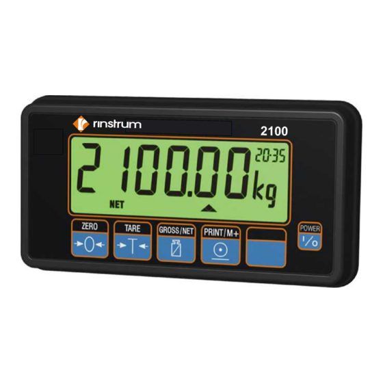
- Page 1 2100 Digital Indicator Quick Start Manual For use with Software Versions 2.0 and above 2100-601-250...
- Page 2 This manual may occasionally make reference to Trade Use settings of the 2100. Only properly marked Trade Certified versions of the 2100 can be used in Legal for Trade applications. Trade Certification is only available on 2100 instruments with software Versions 2.0 and above.
-
Page 3: Table Of Contents
Rinstrum - 2100 Digital Indicator Quick Start Manual Rev 2.50 Table of Contents 1. INTRODUCTION ............4 1.1. Approvals ............... 4 1.2. Features ..............4 1.3. rin-SMART Software Options ......... 4 1.4. Manuals ..............4 2. SPECIFICATIONS ............5 3. WARNINGS ..............6 3.1. -
Page 4: Introduction
Rinstrum - 2100 Digital Indicator Quick Start Manual Rev 2.50 1. Introduction This manual contains information on the installation, calibration and setup of the 2100. 1.1. Approvals • NSC S403 approval (6000 divisions at 1µV/division). • NMI TC6033 approval (6000 divisions at 1µV/division). -
Page 5: Specifications
Rinstrum - 2100 Digital Indicator Quick Start Manual Rev 2.50 Specifications Performance Display Backlit alphanumeric LCD with six 27mm high digits Backlight LED backlight with adjustable brightness Display Resolution Up to 30,000 divisions, minimum of 0.25µV/division (Trade 6000 divisions at 1µV/division) -
Page 6: Warnings
Rinstrum - 2100 Digital Indicator Quick Start Manual Rev 2.50 Warnings 3.1. General • Instrument not to be subject to shock, excessive vibration or extremes of temperature (before or after installation). • Inputs are protected against electrical interference, but excessive levels of electro-magnetic radiation and RFI may affect the accuracy and stability. -
Page 7: Installation
(until display blanks). 4.1. Special Function Key • The Special Function Key on the 2100 ships as a blank key. If any of the special functions are to be used on the indicator it is important that the matching function key sticker (supplied) is applied to the keypad. -
Page 8: Connections
Rinstrum - 2100 Digital Indicator Quick Start Manual Rev 2.50 Connections 5.1. Connecting Shields To obtain full EMC or for RFI immunity with the 2100, the load cell shield MUST be connected electrically to the metal shell of the DB9 connector. Refer to diagrams below or to instructions supplied with the connector. -
Page 9: Cable Shield Connection And Earthing
• The 2100 enclosure is directly connected to the shield connections on the cables. • The 2100 should be connected to earth via a single reliable link to avoid earth loops. • Where each instrument is separately earthed, interconnecting cable shields should be connected at one end only. -
Page 10: Load Cell Connection
Rinstrum - 2100 Digital Indicator Quick Start Manual Rev 2.50 5.4. Load Cell Connection 5.4.1. 6-Wire Connection Note: Sense lines MUST be connected. 5.4.2. 4-Wire Connection For more information on shielding refer to page 8. Page 10... - Page 11 Rinstrum - 2100 Digital Indicator Quick Start Manual Rev 2.50 5.4.3. Auxiliary Connection For more information on shielding refer to page 8. Note: Do NOT connect unused pins. For more information refer to page 9. Remote Display 2100 Pin Remote Display Plug...
-
Page 12: Full Setup
Rinstrum - 2100 Digital Indicator Quick Start Manual Rev 2.50 5.4.4. IO Connections 5.4.5. Power Warning For 2100 use only 10-15 VDC Voltages outside this range may cause improper operation or damage. Note: Variants of the 2100 may require different power requirements. - Page 13 Rinstrum - 2100 Digital Indicator Quick Start Manual Rev 2.4 Underline = Defaults BUILD Decimal Point Position 000000, 00000.0, 0000.00, 000.000, 00.0000, 0.00000 Accept DP⊗ Maximum Capacity SEL changes position, EDT changes digit. Accept CAP⊗ Resolution (Count-By) 1, 2, 5, 10, 20, 50, 100 Accept RES⊗...
- Page 14 Rinstrum - 2100 Digital Indicator Quick Start Manual Rev 2.4 Underline = Defaults Zero Calibration Routine Remove all weight. ZERO⊗ OK starts routine (Z.in P displays). (Current weight displays) ITM key to exit, OK to repeat routine. Span Calibration Routine Add test weight.
- Page 15 Rinstrum - 2100 Digital Indicator Quick Start Manual Rev 2.4 SPEC OP.PC Security Passcode for (0000 no passcode). Accept Operator Menu Setup Set 4 digit passcode (eg. 1234). SEL changes position, EDT changes digit. Activated only when FULL.PC is also set.
- Page 16 Rinstrum - 2100 Digital Indicator Quick Start Manual Rev 2.4 Underline = Defaults SPEC ctd. AUT.OFF Automatic Power Off NEVER, 20 S, 30 S, 60 S, 300 S, 600 S Accept (Seconds of inactivity before power down) AUX.DSP Auxiliary Display (Time)
- Page 17 Rinstrum - 2100 Digital Indicator Quick Start Manual Rev 2.4 SERIAL PRN.ROW Row Padding on Printout Accept 00.0 to 10.10 ctd. 00.00 Number of line feeds to add before printout. 00.00 Number of line feeds to add after printout. If padding is set to 10 then a form feed character is sent.
- Page 18 Rinstrum - 2100 Digital Indicator Quick Start Manual Rev 2.4 Underline = Defaults SET.PTS OPTN B Accept - G O H - (Default) ctd. -none Gross Over High -none Same as OPTN A except: Active Net Under Low Single F Fast Fill used in conjunction with Slow Fill.
- Page 19 Rinstrum - 2100 Digital Indicator Quick Start Manual Rev 2.4 CLOCK TIME Time Setting 24 hour clock Set time in the format HH.MM Accept HH.MM.SS displays SEL changes position, EDT changes digit. DATE Date Setting Accept Set day and month in the format DD.MM DD.MM.YY displays...
-
Page 20: Safe Setup
Rinstrum - 2100 Digital Indicator Quick Start Manual Rev 2.4 Safe Setup Safe Setup provides access to configure the instrument without access to trade or calibration specific items. • Ensure instrument is On. Press the <GROSS/NET> and <POWER> keys together for two seconds. - Page 21 Rinstrum - 2100 Digital Indicator Quick Start Manual Rev 2.4 • The 2100 will display the installed options and prompt for a new license code. (eg. SERIAL is displayed if the RS-232 Serial Option is installed). • The <GROSS/NET> key changes the position and the <PRINT/M+>...
-
Page 22: Rs-485 Communications
Rinstrum - 2100 Digital Indicator Quick Start Manual Rev 2.4 10. RS-485 Communications The 2100 is compatible with the RI 0080 RS-232 to RS-485 serial converter. There is no need to provide external power to the RI 0080 module as this is provided directly by the 2100. -
Page 23: Diagnostic Errors
Rinstrum - 2100 Digital Indicator Quick Start Manual Rev 2.4 13. Diagnostic Errors Error Description Action Power supply voltage too low. Check supply E00001 Power supply voltage too high. Check scale / E00002 cables Load cell excitation voltage too low.
Need help?
Do you have a question about the 2100 and is the answer not in the manual?
Questions and answers