Rinstrum 400 Series Operator's Manual
Summing indicator
Hide thumbs
Also See for 400 Series:
- Reference manual (150 pages) ,
- Quick start manual (64 pages) ,
- Operator's manual (36 pages)
Table of Contents
Advertisement
Quick Links
Advertisement
Table of Contents

Related Manuals for Rinstrum 400 Series


Summary of Contents for Rinstrum 400 Series
- Page 1 400 Series (K481) Summing Indicator Operator Manual RI00-618-100...
- Page 2 Rinstrum Pty Ltd. Disclaimer Rinstrum Pty Ltd reserves the right to make changes to the products contained in this manual in order to improve design, performance or reliability. The information in this manual is believed to be accurate in all respects at the time of publication, but is subject to change without notice.
-
Page 3: Table Of Contents
Operator Manual - Software Version 1.x & 2.x Table of Contents 1. INTRODUCTION..............2 2. SAFETY ................3 2.1. Operating Environment ..........3 2.2. Electrical Safety ............3 2.3. Cleaning ..............3 3. BASIC OPERATION.............4 3.1. User Interface Display and Controls ......4 3.2. Basic Operation............8 3.3. -
Page 4: Introduction
Operator Manual - Software Version 1.x & 2.x 1. Introduction This precision digital summing indicator can sum up to nine slave indicators. The summing indicator will show an error message (------) if any of the slave weights are negative or if there is a mix of gross and net weights, as defined by Technical Schedule S1/0/A. -
Page 5: Safety
Operator Manual - Software Version 1.x & 2.x 2. Safety 2.1. Operating Environment • Operating Temperature: –10 to 50°C • Humidity: <90% non-condensing • Operating Voltage: Shown on Rear Label 2.2. Electrical Safety • For your protection all mains electrical hardware must be rated to the environmental conditions of use. -
Page 6: Basic Operation
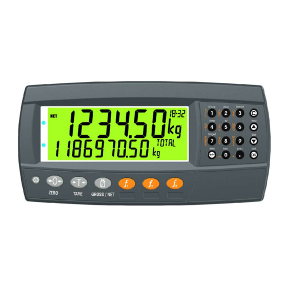
Operator Manual - Software Version 1.x & 2.x 3. Basic Operation 3.1. User Interface Display and Controls Overview Code Description Display Numeric Keypad Function Keys (user defined) Function Keys (Fixed) Power Key Page 4 004R-601-170... - Page 7 Operator Manual - Software Version 1.x & 2.x Display Code Description Primary Annunciators Primary Display Auxiliary Display Primary Units Secondary ID Miscellaneous Annunciators Secondary Units Secondary Display Page 5 004R-601-170...
- Page 8 Operator Manual - Software Version 1.x & 2.x Primary Annunciators Symbol Name Description Visible when the displayed reading is HOLD held. Visible when the displayed reading represents Net weight. Visible when the gross reading is within ± ZERO ¼ of a division of true zero. Visible when the displayed reading is not MOTION stable.
- Page 9 Operator Manual - Software Version 1.x & 2.x Keypad Code Description Numeric Button White Characters Additional Functions (Hold 2 seconds) Orange (Alpha and Symbols) Characters Cancel Undo last command; step backwards (including in menus). Move cursor backwards; previous option Down Move cursor forwards;...
-
Page 10: Basic Operation
Operator Manual - Software Version 1.x & 2.x 3.2. Basic Operation Power Key ON Instrument OFF Instrument Zero Key Page 8 004R-601-170... - Page 11 Operator Manual - Software Version 1.x & 2.x Tare Key Gross/Net Key Page 9 004R-601-170...
-
Page 12: Stability Considerations
Operator Manual - Software Version 1.x & 2.x 3.3. Stability Considerations Some functions (E.g. Tare and Zero) require a stable weight. These functions will wait for up to 10 seconds for stable weight. 3.4. Security Most functions can be locked in setup. The locking options are: •... -
Page 13: Additional Functions
Operator Manual - Software Version 1.x & 2.x 4. Additional Functions 4.1. Product Selection 4.2. Add Product Page 11 004R-601-170... -
Page 14: Delete Product
Operator Manual - Software Version 1.x & 2.x 4.3. Delete Product 4.4. Rename Product 4.5. Clock Page 12 004R-601-170... -
Page 15: View
Operator Manual - Software Version 1.x & 2.x 4.6. View 4.7. Report Page 13 004R-601-170... -
Page 16: Totals
Operator Manual - Software Version 1.x & 2.x 4.8. Totals 4.9. IDs Page 14 004R-601-170... -
Page 17: Targets
Operator Manual - Software Version 1.x & 2.x 4.10. Targets Target (Setpoint Targets) 4.11. Lock 4.12. Page 15 004R-601-170... - Page 18 Operator Manual - Software Version 1.x & 2.x M4221 Ethernet Module Page 16 004R-601-170...
-
Page 19: Function Keys
Software Version 1.1x & 2.x 5. Function Keys 5.1. Introduction The instrument has 3 function keys. External keys can also be used. The function of the keys can be configured to any of the functions detailed below 5.2. Print Page 17 004R-624-110... -
Page 20: Single
Software Version 1.1x & 2.x 5.3. Single 5.4. Test Page 18 004R-624-110... -
Page 21: Prd.sel
Software Version 1.1x & 2.x 5.5. Prd.Sel Product Select. Short Press: Cycles the display of available totals for the current product Long Press: Select product by number Page 19 004R-624-110... -
Page 22: Slave
Software Version 1.1x & 2.x 5.6. SLAVE A short press of the slave key will cycle through each slave weight followed by each sub total on the lower display. Slave 1 Slave 2 SLAVE SLAVE SLAVE Slave 1 - Slave 2 Page 20 004R-624-110... -
Page 23: Error Messages
Software Version 1.1x & 2.x 6. Error Messages 6.1. Weighing Errors These messages show status messages or errors that may occur during normal weighing operation. Error Description Resolution U.LOAD The weight is below the Increase the weight minimum allowable or decrease the weight reading. -
Page 24: Summing Errors
Software Version 1.1x & 2.x 6.2. Summing Errors Error Description No Resp One or more slaves are not responding. Slave shown in the bottom right display. Hdr Adr The address in the command header is bad Hdr Cmd The command in the command header is bad Hdr Reg The register in the command header is bad Hdr Dlm... - Page 25 Notes...
Need help?
Do you have a question about the 400 Series and is the answer not in the manual?
Questions and answers