Table of Contents
Advertisement
Quick Links
Advertisement
Table of Contents

Related Manuals for Thermo Scientific PDM3700


Summary of Contents for Thermo Scientific PDM3700
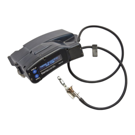
- Page 1 Model PDM3700 Personal Dust Monitor Part Number 42-009904-3700 25Mar2016...
- Page 2 © 2014 Thermo Fisher Scientific. All rights reserved. Specifications, terms and pricing are subject to change. Not all products are available in all countries. Please consult your local sales representative for details. TEOM is a registered trademark of Thermo Fisher Scientific. Other trademarks are the property of their respective holders.
- Page 3 Warranty Seller warrants that the Products will operate or perform substantially in conformance with Seller's published specifications and be free from defects in material and workmanship, when subjected to normal, proper and intended usage by properly trained personnel, for the period of time set forth in the product documentation, published specifications or package inserts.
- Page 4 covered by the warranty hereunder, Buyer shall pay or reimburse Seller for all costs of investigating and responding to such request at Seller's then prevailing time and materials rates. If Seller provides repair services or replacement parts that are not covered by the warranty provided in this warranty, Buyer shall pay Seller therefor at Seller's then prevailing time and materials rates.
- Page 5 Thermo Fisher Scientific’s compliance with these Directives, the recyclers in your country, and information on Thermo Fisher Scientific products which may assist the detection of substances subject to the RoHS Directive are available at: www.thermoscientific.com/WEEERoHS. Thermo Fisher Scientific PDM3700 Instruction Manual...
- Page 6 30 CFR Parts 70, 71 & 90. All charging of these battery packs shall take place while installed in the PDM3700 and in fresh air in Battery Charging stations as defined in 30 CFR 75.340 or fresh air above ground.
- Page 7 30 CFR Parts 70, 71 & 90. All charging of these battery packs shall take place while installed in the PDM3700 and in fresh air in Battery Charging stations as defined in 30 CFR 75.340 or fresh air above ground.
- Page 8 Line Conducted RF Susceptibility EN 61000-4- 0.15-80Mhz @ 3 Vrms, 1kHz AM 80% 6:96+A1:01 modulation Voltage Dips and Dropouts EN 61000-4-11:2004 -100% for 0.5 cycles -100% for 1 cycle -30% for 25 cycles -100% for 250 cycles PDM3700 Instruction Manual Thermo Fisher Scientific...
- Page 9 The following information can be used to determine the power service requirements of this product: Line Voltage 120 V ~ 60 Hz 20 Amp 240 V ~ 50 Hz 10 Amp Charger Fuse Part Number Current Rating 04-003268 2A time delay Thermo Fisher Scientific PDM3700 Instruction Manual...
- Page 10 CFR Parts 70, 71 & 90. This includes changing the battery packs, sample pump, cleaning the sample inlet, and other maintenance items as described in the operators manual. ▲ WARNING Do not operate the PDM3700 if its case is damaged or otherwise compromised. ▲ PDM3700 Instruction Manual Thermo Fisher Scientific...
- Page 11 (recycling is preferable, contact Thermo Fisher Scientific for further information). Do not dispose of the battery pack in fire or heat.▲ Equipment Damage DO NOT use acetone to clean any parts of the PDM3700. ▲ Equipment Damage When moving the battery pack to access the wire connections, be sure to minimize stress on the wires and connectors.
- Page 12 This label is affixed to the back of the instrument. Only the parts listed should be used in order to maintain certifications. Note All labels must be affixed to the instrument and not obscured for the unit to be approved for sampling. ▲ viii PDM3700 Instruction Manual Thermo Fisher Scientific...
-
Page 13: Table Of Contents
First Sample - Screen #4 ..............2-23 Second Sample Screen ..............2-23 Sample Complete Screens ..............2-23 Sampling Complete - Screen #1 ............. 2-23 Status Conditions ................2-24 View Status Screen ................. 2-24 Thermo Fisher Scientific PDM3700 Instruction Manual... - Page 14 Auditing the Tilt Sensor ..............5-17 Periodic Maintenance ................ 5-20 Opening the PDM3700 Case ............5-21 Installing the PDM3700 Cover Panel ..........5-23 Performing Sample Path and Case Leak Checks ........ 5-25 Replacing the Battery Pack ..............5-30 ...
- Page 15 Instrument Diagnostics ............... 6-2 Leak Testing..................6-4 Sample Path – Instrument Plumbing ..........6-5 Case – Battery Compartment ............6-7 Appendix A Parts and Consumables .................. A-1 Thermo Fisher Scientific PDM3700 Instruction Manual...
-
Page 17: Chapter 1 Introduction
The PDM3700 contains all the hardware and software necessary to measure and store ambient particulate mass concentration. The mass measurement is a filter-based direct mass monitoring instrument using proprietary TEOM and momentum compensation technologies. - Page 18 The high contrast display provides basic data and statistics for the system, including status conditions. An additional PC-based user interface is provided through WinPDM communication software. The PDM3700 is powered by one internal lithium-ion battery assembly. See Table 1–1 Table 1–2...
- Page 19 The PDM3700 battery charger (Figure 1–2) is a separate unit that connects to the PDM3700 and provides a charging station as well as communication functions. A separate external power cord and communication/charge cable must be installed to operate the charger (Chapter 2).
-
Page 20: Advanced Features
Introduction Advanced Features Advanced The PDM3700 offers a number of features to provide superior data quality, ease of use, and flexibility for the user. The following is a partial list Features of the instrument’s advanced features: 30-minute mass concentration measurement in the range of 0.1 to 10 ●... -
Page 21: Organization Of Manual
Manual sections explain the advanced features of the PDM3700. Users should read and understand earlier sections before attempting procedures described later in the manual. The following list provides an overview of the topics handled in each section of this manual: Chapter 1 “Introduction”... -
Page 22: Operating Parameters
Introduction Operating Parameters Operating The PDM3700’s flow rate is 2.2 l/min 2.5% when calibrated at set point. Temperature set points of the air heater and TE heater are set automatically Parameters by selecting the appropriate operating temperature (Figure 3–12) when programming a shift (Section 3). -
Page 23: Battery Safety
Sensor Pump Mass Transducer Figure 1–3. PDM3700 flow path Battery Safety The PDM3700 is powered by one internal lithium-ion battery pack assembly. The batteries can be charged daily through the communication/charge cable and charging unit (Figure 1–2). Be sure to charge the PDM3700 unit in a fresh-air environment. - Page 24 30 CFR Parts 70, 71 & 90. All charging of these battery packs shall take place while installed in the PDM3700 and in fresh air in Battery Charging stations as defined in 30 CFR 75.340 or fresh air above ground.
- Page 25 Introduction Battery Warnings WARNING Do not operate the PDM3700 if its case is damaged or otherwise compromised. ▲ WARNING Only MSHA certified individuals may perform maintenance, calibration and sampling pursuant to 30 CFR Parts 70, 71 & 90. This includes changing the battery packs, sample pump, cleaning the sample inlet, and other maintenance items as described in the operator’s manual.
-
Page 27: Chapter 2 Basic Operation
(PDM) and connecting it to the charger, installing a TEOM filter and setting up basic sample runs. Upon receiving the PDM3700 unit, ensure that a TEOM filter is installed in the mass transducer and connect the unit to the charger (Figure 2–1). -
Page 28: Basic Components
Quick Start Guide (Laminated) CD-ROM (WinPDM software) Operational While the PDM3700 may be used as a stand-alone device, many of its features require the use of additional equipment. To access the full Requirements functionality of the PDM3700 the following items will be needed: Laptop or desktop personal computer (PC) running Microsoft ●... -
Page 29: Installing Optional Belt Loops
Installing Optional The PDM3700 is shipped with belt loops in the compilation package. The belt loops can be installed on the unit to allow the PDM3700 to be worn Belt Loops on an equipment belt during operation. To install the belt loops, remove... - Page 30 Basic Operation Installing Optional Belt Loops The PDM3700 is designed to operate in a position where the instrument display is oriented at the top of the unit. The sampler includes an integrated tilt sensor that automatically compensates the measurements when the position of the monitor moves. This is used to compensate for...
-
Page 31: Connecting To The Charger
Charging must be completed in a fresh air environment. 1. Locate the PDM3700 charger and its power cord, attach the power To connect your PDM3700 to a cord to the back of the charger and then install the charger’s power cord into an approved, grounded power source. - Page 32 Basic Operation Connecting to the Charger 3. Set the alignment post into the hole in the back of the PDM3700. Turn the handle to tighten the connection screw into the connector (Figure 2–6 Figure 2–7). Figure 2–6. Setting the charger connector onto the unit Figure 2–7.
- Page 33 Basic Operation Connecting to the Charger 6. If the charger and the PDM3700 are both functioning correctly, the LEDs on the front of the charger will indicate the status of the unit (Figure 2–8). a) Solid grey (or off): Indicates that the PDM3700 is not properly connected to the charger, or the charger power is off.
-
Page 34: Removing A Teom Filter
30 CFR Parts 70, 71 & 90. All charging of these battery packs shall take place while installed in the PDM3700 and in fresh air in Battery Charging stations as defined in 30 CFR 75.340 or fresh air above ground. - Page 35 The tines of the lower fork should straddle the hub of the filter base (Figure 2–11 Figure 2–12). Figure 2–11. Filter tool Figure 2–12. Removing the TEOM filter with the filter tool Thermo Fisher Scientific PDM3700 Instruction Manual...
-
Page 36: Installing A Teom Filter
Note Do not twist or tilt the filter exchange tool from side-to-side while removing the filter from the TE. This will damage the TE. ▲ Installing a The PDM3700 unit is shipped with a Tapered Element Oscillating Microbalance (TEOM) filter installed on the tapered element (TE), but the TEOM Filter filter must be changed daily (or with each shift). - Page 37 90° and applying the filter tool each time. Figure 2–17. Back of filter exchange tool Figure 2–18. Setting the filter 5. Install the mass transducer back into the PDM3700 unit. Thermo Fisher Scientific PDM3700 Instruction Manual 2-11...
-
Page 38: Pdm Display
However, during the warm-up time and sampling cycle, the PDM3700 will continue to activate its LED display until the sample run ends. At the end of the sample run, after 30 seconds of inactivity, the PDM3700 will then automatically turn off its LED display. If the PDM3700 is connected to the WinPDM software, the PDM3700 display will stay on continuously. - Page 39 Basic Operation PDM Display Figure 2–20. First manual sample run screen hierarchy Thermo Fisher Scientific PDM3700 Instruction Manual 2-13...
-
Page 40: Idle Screen
Basic Operation Idle Screen Idle Screen When the PDM3700 is turned on and not sampling, the unit will briefly display the Thermo Fisher Scientific Splash screen (Figure 2–21) followed by the Idle screen. Press the “A” (WAKE UP) button (Figure 2–19) located... -
Page 41: Start Sampling Screen
(Figure 2–23). After 30 seconds of inactivity in the Start Sampling screen, the PDM3700 will automatically turn off its LED display. Press the “A” button to reactivate the LED display and to bring up the Idle screen, or the Sampling Complete Screen #1 (if the sample run is complete). -
Page 42: Exit Screen
PC is not available or when a manual sample is desired. If the conditions Manual Sample change or the employees moves to a different area, a second manual sample run can be started running concurrently with the first sample run. 2-16 PDM3700 Instruction Manual Thermo Fisher Scientific... -
Page 43: Starting A Second Sample Run
1. In the First Sample Screen #1 (Figure 2–27), press the “A” and “B” To start a second manual sample run: buttons simultaneously to display the Reset Sample 2 screen (Figure 2– 28). Figure 2–28. Reset Sample 2 screen Thermo Fisher Scientific PDM3700 Instruction Manual 2-17... -
Page 44: Second Sample Screen
During the sampling run, the PDM3700 will run automatically until the sample cycle ends. At the end of the sample run, after 30 seconds of inactivity, the PDM3700 will turn off its LED display. Press the “A” button to reactivate the LED display. -
Page 45: Stopping A Sample Run
Stop the sample runs by pressing the “A” and “B” buttons simultaneously, and the Stop Sampling screen will display. Figure 2–31. Stop Sampling screen Thermo Fisher Scientific PDM3700 Instruction Manual 2-19... -
Page 46: Stopping During Warm Up
Sampling Complete - Screen #1. This action will stop both the first and second manual sample run (if you have started a second manual sample run). 2-20 PDM3700 Instruction Manual Thermo Fisher Scientific... - Page 47 Basic Operation Sample Run Screens Sample Run The PDM3700 displays several screens during a sample run. Information includes cumulative exposure and other data, as well as whether the Screens instrument is operating properly (refer to the “System Status” section later in this chapter for more information on status.
-
Page 48: First Sample - Screen #2
During the sampling run, the PDM3700 will run automatically until the sample cycle ends. After 30 seconds of inactivity at the end of the sample run, the PDM3700 will turn off its LED display. Press the “A” button to reactivate the LED display. This action will display the Sampling Complete - Screen #1. -
Page 49: First Sample - Screen #4
After 30 seconds of inactivity at the end of the sample run, the PDM3700 will turn off its LED display. Press the “A” button to reactivate the LED display and to bring up the Sampling Complete -... -
Page 50: Status Conditions
Refer to the following section “Status Conditions” for more information on status codes. After 30 seconds of inactivity in the Sampling Complete Screen #1, the PDM3700 will turn off its LED display. Press the “A” button to reactivate the LED display. Status The PDM3700 monitors its performance during a sample run and registers any status conditions logged during the sample run(s). -
Page 51: Viewing Status Codes During A Sample Run
#2, press the “A” and “B” buttons simultaneously to display the View Status screen (Figure 2–39). When in the View Status screen, press the “A” button to display the Status screen (Figure 2-37). Thermo Fisher Scientific PDM3700 Instruction Manual 2-25... -
Page 52: Status Codes
(Chapter 4) after the sample run has ended. Figure 2–40. Status screen If the PDM3700 unit has encountered more than one status condition, pressing the “B” button repeatedly allows viewing of all the status conditions that occurred during the primary sample run. - Page 53 Sample Start Time Missed The programmed sample start time was missed The PDM3700 status codes are as follows: TE not detected. This condition is reported when the PDM3700 unit ● senses that the mass transducer has been removed from the unit.
-
Page 54: Downloading Data
1. Following a primary or programmed sample run, connect the unit: PDM3700 unit to its charger and the charger to the PC. Ensure that the charger and the PDM3700 are both functioning correctly. 2. Start the WinPDM software application and select the “Download Sample”... - Page 55 12. Select the “Save” button to save the data file. Note The WinPDM software automatically names the data files with the date and start hour of the sample run (yyyy-mm-dd-hh), the PDM3700 unit serial number, the Mine ID number, and the vendor/instrument code.
- Page 56 14. Click “Cancel” if you wish to exit the Download Graph screen. 15. After saving the data, please refer to MSHA instructions as to how to submit the .MSHA file to MSHA for review and validation. 2-30 PDM3700 Instruction Manual Thermo Fisher Scientific...
-
Page 57: Chapter 3 Using The Winpdm Software
The PDM3700 will accommodate programmed shift-lengths from 1 minute to 24 hours. After the PDM3700 unit has completed a sample run (immediate or programmed), you can download the data collected to a personal computer (PC) for analysis. - Page 58 1. Exit all Windows programs currently running on your PC. To install WinPDM onto a PC: 2. Place the PDM3700 software CD-ROM in the CD-ROM drive. 3. Open the “Software” folder on the PDM3700 software CD-ROM, then open the “WinPDM Setup.exe” file located in the Software folder.
-
Page 59: Starting Winpdm
WinPDM icon on the PC’s desktop to start the WinPDM communications software program. Starting WinPDM The PDM3700 must be connected to the charger and a PC to use the WinPDM program. Refer to Chapter 2 for information on connecting the PDM3700 unit to the charger and establishing communications. - Page 60 The “PDM - COM1” screen (Figure 3–3) will display. Note If the connection between the PDM3700 and the PC is successful, the unit’s serial number will display in the top, right-hand corner of the screen. ▲ Figure 3–3. Connect screen 6.
-
Page 61: Exiting The Winpdm Software Application
Using the WinPDM Software Starting WinPDM Figure 3–4. WinPDM showing "Not Connected" Note If the cable connections are secure, and the PDM3700 is functioning correctly, but you still cannot make a successful connection between the PDM3700 and PC, contact Thermo Fisher Scientific.▲... -
Page 62: Starting A Programmed Sample Run
“B” (“SCROLL”) button on the PDM3700's display. If you want to stop or change a programmed sample run, you must connect the PDM3700 unit to its charger and to your PC, and use the WinPDM software to perform any necessary changes to the sample run. - Page 63 At the 35-minutes mark, the PDM - COM1 screen will display a “Warming” message on the screen for 35-minutes. After the warming period ends, the PDM3700 unit will begin its sample run and the PDM - COM1 screen will display a “Running” message on the screen (Figure 3–...
- Page 64 Using the WinPDM Software Starting a Programmed Sample Run Figure 3–7. Warming Figure 3–8. Running PDM3700 Instruction Manual Thermo Fisher Scientific...
-
Page 65: Stopping A Programmed Run
You can stop a programmed sample run at any time after you have programmed the sample run using the WinPDM software. Programmed Run 1. Connect the PDM3700 unit to its charger and the PC, and ensure that Follow these steps to stop a programmed sample run: the charger and the PDM3700 are both functioning correctly. -
Page 66: Pdm Display
Using the WinPDM Software PDM Display PDM Display The display on the top panel of the PDM3700 allows users to navigate through the instrument’s firmware screens by pressing the “A” and “B” During Programmed buttons. But when the WinPDM communications software is used to... -
Page 67: Configuring A Program Shift
When in the PDM - COM1 screen, select the “Program Shift” button to display the Program Shift screen. These values will be stored in the PDM3700’s data storage buffer, and will display on the “Dust Data Card” that can be downloaded at the end of the sample run. - Page 68 The instrument stores the field information from the last programmed shift. This prompt acts as a reminder to confirm that the shift information has not changed (Figure 3–14). Figure 3–14. Field Entry Confirmation screen 3-12 PDM3700 Instruction Manual Thermo Fisher Scientific...
- Page 69 PDM3700 unit for sampling. 6-7. Sample Start Time. This field contains the start date and time that ● the PDM3700 unit will begin its programmed sample run (first sample). Note This must be at least 35 minutes later than current time to accommodate 35 minute warm-up time.
-
Page 70: Setting Up Programmed Sample Parameters
(“4. Mine Name”) and the company name (“5. Company Name”). 3. Enter the start date and time that you want the PDM3700 unit to begin its programmed sample run in the white box located under “6-7. Sample Start Time.” Also, you can place your cursor on the small black arrow/triangles located on the right-hand side of the white box and click with your mouse to increase or decrease the start date and time. - Page 71 6. Enter the 4-digit mechanized mining unit (MMU) identification code and the 4-digit designated area/designated work position (DA/SA) for the MMU that will be using the PDM3700 unit, if necessary, in the box under “10. MMU DA/SA.” 7. Enter the 3-digit occupational code of the operator that will be using the PDM3700 unit, if necessary, in the box under “11.
-
Page 72: Program Shift Setup Problems
At the 35-minutes mark, the PDM - COM1 screen will display a “Warming” message on the screen for 35-minutes. After the warming period ends, the PDM3700 unit will begin its sample run and the PDM - COM1 screen will display a “Running” message on the screen. -
Page 73: Correcting Shift Setup Problems
(refer to Starting a Programmed Sample Run earlier in this chapter for more information). If you continue to get a Warning/Confirmation screen after you believe you have entered correct values, contact Thermo Fisher Scientific. Thermo Fisher Scientific PDM3700 Instruction Manual 3-17... -
Page 75: Chapter 4 Viewing And Saving Data
After you have performed a programmed sample run, you must use the WinPDM software and the RS232 cable to download data from the PDM3700 unit. Two data files are available for download; the first is a file with a comma-separated value (.csv) file format. The second file is in .msha format, which must be submitted to MSHA for validation. -
Page 76: Configuring Data Downloading
(hh:mm:ss, weekday, mm/dd/yyyy), and size of the data file (Bytes). Each time that you perform a sample run, the PDM3700 unit logs the sample data and displays the data file information on this screen. It will continue to list the sampling events in the order that they are performed in this screen. -
Page 77: Downloading Data
1. Following a primary or programmed sample run, connect the To download data from the PDM3700 unit: PDM3700 unit to its charger and the charger to the PC. Ensure that the charger and the PDM3700 are both functioning correctly. 2. Start the WinPDM software application and select the “Download Sample”... - Page 78 Viewing and Saving Data Downloading Data Figure 4–4. Download Data screen with progress bar 5. If the PDM3700 unit encountered any status conditions during the sample run, the “Status List” screen will display (Figure 4–5). Figure 4–5. Status List screen...
- Page 79 Select the “Save” button. Note The WinPDM software automatically names the status code file with the date and start hour of the sample run (yyyy-mm-dd-hh), the PDM3700 unit serial number, the Mine ID number, word “STATUS,” and the vendor/instrument code. For example: 2014-08-19-06-0212502-0503836- STATUS-A.csv or .msha.
- Page 80 Note To ensure proper data storage and file information, refer to MSHA guidelines for data reporting requirements. ✳ 12. To send the shift data to MSHA, the data file must be saved to the local computer. Press the “Save data” button. PDM3700 Instruction Manual Thermo Fisher Scientific...
- Page 81 Downloading Data Note The WinPDM software automatically names the data file with the date and start hour of the sample run (yyyy-mm-dd-hh), the PDM3700 unit serial number, the Mine ID number, and the vendor/instrument code. For example: 2014-08-19-06-0212502-0503836-A.csv or .msha.
-
Page 82: Download Graph Screen
Downloaded Logging Parameters drop-down menu. When in the Download Graph screen, you also can display and print the “Dust Data Card,” save the information, or exit the screen by selecting the “Cancel” button. PDM3700 Instruction Manual Thermo Fisher Scientific... -
Page 83: Dust Data Card Screen
“Print” button that is located in the top, left-hand corner of the screen. This hard copy record will display the data entered when the sample run was first programmed, the results that were recorded, and the information entered in the Shift Information screen. Thermo Fisher Scientific PDM3700 Instruction Manual... -
Page 84: Viewing Data Files
60 seconds. Therefore, the data records are 1-minute increments. The .msha file is in a special format required by MSHA and is used to validate or void the sample. Do not modify the file. 4-10 PDM3700 Instruction Manual Thermo Fisher Scientific... - Page 85 Viewing and Saving Data Viewing Data Files Program shift information Header/footer information Data values of logging parameters Figure 4–10. Excel file with downloaded data Thermo Fisher Scientific PDM3700 Instruction Manual 4-11...
-
Page 86: Viewing A Status List
4–11). The file will contain the time that the status code occurred in the left-hand column, and the name of the status code in the right-hand column. Status Code Figure 4–11. Status List file 4-12 PDM3700 Instruction Manual Thermo Fisher Scientific... -
Page 87: Viewing Status Codes
4–12). You can locate the status code in the second column under the “STATUS CODE” heading. Note Status codes will only be reported for the duration they are present. ✳ Figure 4–12. Data file with status codes Thermo Fisher Scientific PDM3700 Instruction Manual 4-13... -
Page 89: Chapter 5 Maintenance And Calibration
Maintenance and Calibration This section describes the procedures involved in verifying the calibration of the PDM3700 Monitor and maintaining the consistent operation of the hardware. In addition to regularly scheduled maintenance, the unit may require other maintenance as necessary, including replacing the battery, or other procedures. -
Page 90: Removing The Mass Transducer
Mass removed from the unit. Transducer 1. Locate the TE handle on the side of the PDM3700 and slide it all the To remove the mass transducer: way to the right as shown in to unlock the mass transducer, as shown in Figure 5–1. - Page 91 Removing the Mass Transducer Figure 5–2. Removing the mass transducer 3. When ready, reinstall the mass transducer into the PDM3700 by aligning the flat side of the transducer toward the center of the PDM3700 and pushing it in until it seats firmly in place (Figure 5–3...
-
Page 92: Cleaning The Grit Pot
Silicone lubricant ● 1. Remove the mass transducer. To clean the grit pot 2. Locate the grit pot on the right-hand side of the PDM3700 unit (Figure 5–5). Figure 5–5. Photo showing location of grit pot 3. Gently remove the grit pot from the nozzle. - Page 93 Figure 5–7. Instrument Inlet and Cyclone Nozzle 6. Reinstall the grit pot and mass transducer. Note A light coating of silicone lubrication on the outside of the plastic nozzle can be used to prevent leaks. ✳ Thermo Fisher Scientific PDM3700 Instruction Manual...
-
Page 94: Cleaning The Mass Transducer And Sample Lines
1. Disconnect the sample line from the inlet assembly (Figure 5–8). Use To clean the mass transducer and sample lines: care to ensure that the tubing does not break during removal. Disconnect Here Figure 5–8. Disconnect the sample line PDM3700 Instruction Manual Thermo Fisher Scientific... - Page 95 3. Use canned air then an alcohol swab to clean all surfaces of the mass transducer. 4. Use canned air and an alcohol swab to clean the bell-shaped inlet inside the PDM3700 unit and then direct a stream of air through the bell- shaped inlet (Figure 5–9 Figure 5–10).
- Page 96 6. Direct a stream of air through the end of the sample line removed from the inlet assembly and through the sample inlet on the bracket (Figure 5–11 Figure 5–12). Figure 5–11. Direct a stream of air through the sample line PDM3700 Instruction Manual Thermo Fisher Scientific...
- Page 97 Maintenance and Calibration Cleaning the Mass Transducer and Sample Lines Figure 5–12. Direct a stream of air into the sample inlet Figure 5–13. Loosen screws on rear of bracket Thermo Fisher Scientific PDM3700 Instruction Manual...
- Page 98 Maintenance and Calibration Cleaning the Mass Transducer and Sample Lines Figure 5–14. Open sample inlet assembly bracket Figure 5–15. Slide out inlet 5-10 PDM3700 Instruction Manual Thermo Fisher Scientific...
- Page 99 Maintenance and Calibration Cleaning the Mass Transducer and Sample Lines Figure 5–16. Remove sealing screw using inlet spanner tool Figure 5–17. Clean inlet Thermo Fisher Scientific PDM3700 Instruction Manual 5-11...
- Page 100 Figure 5–18. Inspect o-ring in top of inlet for damage 7. Install a new TEOM filter onto the mass transducer and install the mass transducer into the PDM3700 unit. 8. Reassemble the sample inlet and reattach the sample line to the sample inlet.
-
Page 101: Performing A Flow Audit
(Figure 5–19 Figure 5– 20). Figure 5–19. Flow audit/tubing adapter Figure 5–20. Installing the flow/audit/tubing adapter 3. Connect the PDM3700 unit to the charger and make sure the charger is connected to your PC. Thermo Fisher Scientific PDM3700 Instruction Manual 5-13... -
Page 102: Cleaning The Cyclone And Inlet Tubing
2. Disconnect the sample line from the sample inlet assembly. Remove sample line from instrument cyclone. 3. Remove the grit pot from the PDM3700 unit and ensure that the grit pot and its plastic nozzle are clean (Refer to “Cleaning the Grit Pot”... -
Page 103: Auditing The K0 Number
See Figure 5–26 for position. ✳ 1. Connect the PDM3700 unit to its charger and start the WinPDM To perform a K0 audit: software. 2. When in the PDM – COM1 screen, select the “K0 Audit” button to... - Page 104 5–24). The acceptable error limit is ±10%. If the results are greater than ±10%, repeat the audit. If the audit continues to fail, contact Thermo for support. 7. Remove K0 audit filter and replace with new filter. 5-16 PDM3700 Instruction Manual Thermo Fisher Scientific...
-
Page 105: Auditing The Tilt Sensor
The tilt sensor should be audited once a year. Sensor The PDM3700 is designed to operate in a position where the instrument display is oriented at the top of the unit. The sampler includes an integrated tilt sensor that automatically compensates the measurements when the position of the monitor moves. - Page 106 Figure 5–26. Place instrument in upright position 5. When prompted, position the instrument on the side (mass transducer) as shown in Figure 5–27. Support instrument so it does not move during test. 5-18 PDM3700 Instruction Manual Thermo Fisher Scientific...
- Page 107 Auditing the Tilt Sensor Figure 5–27. Position the instrument on the side as shown 6. When complete, the computer will indicate a pass or fail status (Figure 5–28). Figure 5–28. Tilt Audit Pass/Fail status prompt Thermo Fisher Scientific PDM3700 Instruction Manual 5-19...
-
Page 108: Periodic Maintenance
30 CFR Parts 70, 71 & 90. All charging of these battery packs shall take place while installed in the PDM3700 and in fresh air in Battery Charging stations as defined in 30 CFR 75.340 or fresh air above ground. -
Page 109: Opening The Pdm3700 Case
Opening the PDM3700 Case Opening the Some of the maintenance procedures require the user to remove the cover panel of the case of the PDM3700 unit. A Phillips screwdriver is required PDM3700 Case to remove the cover panel of the unit. - Page 110 Opening the PDM3700 Case Figure 5–29. Cover panel screws Figure 5–30. Screws on top display Equipment Damage Do not attempt to remove the security (non-Phillips head) screws on the top or front of the PDM3700. ✳ 3. Remove the cover panel (Figure 5–31).
-
Page 111: Installing The Pdm3700 Cover Panel
Maintenance and Calibration Installing the PDM3700 Cover Panel Battery Pack Foam Spacer Figure 5–31. PDM3700 with cover panel removed Installing the The cover panel of the PDM3700 may have to be removed to perform certain maintenance tasks (Figure 5–31). PDM3700 Cover Panel WARNING Whenever the PDM3700 case is opened for maintenance, you must perform a case leak check after reassembling the case. - Page 112 Maintenance and Calibration Installing the PDM3700 Cover Panel Figure 5–32. Cover panel gasket checkpoints 4. Install the screws in locations 1 and then 2 and tighten until snug (Figure 5–33). Do not overtighten. These will be tightened to the proper torque specification at a later step. Press down on back of cover panel, aligning holes 3 and 4.
-
Page 113: Performing Sample Path And Case Leak Checks
The entire process is described below. ✳ 1. Disconnect the sample line from the sample inlet assembly. To perform a case leak check: 2. Connect the PDM3700 unit to its charger and start the WinPDM software. Thermo Fisher Scientific PDM3700 Instruction Manual... - Page 114 At this time press a portion of leak check putty onto the pump exhaust muffler. Press firmly, but not so that putty gets stuck in the exhaust muffler opening (Figure 5–38). 5-26 PDM3700 Instruction Manual Thermo Fisher Scientific...
- Page 115 Maintenance and Calibration Performing Sample Path and Case Leak Checks Figure 5–37. Pump exhaust muffler Figure 5–38. Placing the leak check putty Thermo Fisher Scientific PDM3700 Instruction Manual 5-27...
- Page 116 8. Another Warning/Confirmation screen will display with a “Attach the inlet adapter to the PDM” message. Install the suction cup side of the leak check suction cup onto the battery compartment vent that is located below the communication connections on the PDM3700 (Figure 5–40 Figure 5–41).
- Page 117 Figure 5–41. Leak check suction cup installed on battery vent 9. The Calibrate/Audit screen will display with a “Performing case check” message. The PDM3700 unit will perform the case leak check and display a pass or fail message on the Calibrate/Audit screen (Figure 5–...
-
Page 118: Replacing The Battery Pack
30 CFR Parts 70, 71 & 90. All charging of these battery packs shall take place while installed in the PDM3700 and in fresh air in Battery Charging stations as defined in 30 CFR 75.340 or fresh air above ground. - Page 119 Replacing the Battery Pack Battery Pack Foam Spacer Figure 5–43. PDM3700 with cover panel removed 3. Carefully remove the battery pack “A” from the PDM3700 unit. Press the small tab on the wire connection to disconnect the battery wires (Figure 5–44 Figure 5–45).
-
Page 120: Lubricating The Mass Transducer O-Rings
8. Install the mass transducer into the PDM3700 unit. 9. Press the “A” (“WAKE UP”) button on the top panel of the PDM3700 unit to ensure that the display screen appears. 10. If the display screen does not appear, open the case and double-check the battery connections. -
Page 121: Performing A Flow Calibration
1. Remove the PDM3700 cover panel (refer to the instructions earlier in To lubricate the mass transducer O-rings: this chapter for information on opening the case). 2. Locate the mass transducer chamber of the PDM3700 and the two O- rings in the top of the chamber (Figure 5–46 Figure 5–47). - Page 122 2. Disconnect the sample line from the sample inlet assembly. 3. Perform a sample path leak check. 4. Connect the PDM3700 unit to its charger and start the WinPDM software. 5. When in the PDM – COM1 screen, select the “Flow Calibrations”...
- Page 123 10. Increase or decrease the flow rate reading on the flow meter by clicking on the small black arrows located to the right of the “Pump Speed” box (Figure 5–51). Adjust pump speed until the flow meter reads 2.2 lpm. Thermo Fisher Scientific PDM3700 Instruction Manual 5-35...
- Page 124 (from the flow meter) into the “No Restriction” (lpm) white box. Wait 2-3 minutes to ensure the flow meter is stable. 12. Select the “Apply” button. The PDM3700 unit will begin the flow calibration routine and will display a “Please wait, gathering data”...
- Page 125 17. Do Not adjust the pump speed. Enter the Orifice 1 flow rate from the flow meter (typically 2.0 lpm). 18. Select the “Apply” button. The PDM3700 unit will continue the flow calibration routine and will display a “Please wait, gathering data”...
- Page 126 23. Do Not adjust the pump speed. Enter the Orifice 2 flow rate from the flow meter (typically 1.8 lpm). 24. Select the “Apply” button. The PDM3700 unit will continue the flow calibration routine and will display a “Please wait, gathering data”...
- Page 127 28. Install the sample line onto the sample inlet assembly. Note Care must be taken when reinstalling the sample tube onto the sample inlet to prevent cracking, gouging, or otherwise damaging the tubing. ✳ Thermo Fisher Scientific PDM3700 Instruction Manual 5-39...
-
Page 129: Chapter 6 Troubleshooting
Technical Support team can also be contacted via email at: epm.technicalsupport@thermofisher.com Start Up During instrument warm-up, the PDM3700 continuously monitors the operating status for unexpected conditions. If any fault conditions are Diagnostics flagged the screen will flash ‘DIAGNOSTIC FAILURE’. To view the cause of the fault, press the A and B buttons, press ‘B’... -
Page 130: Instrument Diagnostics
Troubleshooting Instrument Diagnostics Instrument During instrument warm-up, the PDM3700 continuously monitors the operating status for unexpected conditions. If any fault conditions are Diagnostics flagged the screen will flash ‘DIAGNOSTIC FAILURE’. To view the cause of the fault, press the A and B buttons, press ‘B’ to scroll until the ‘View Failures’... - Page 131 FLOW RATE (VOLTS) Board Defective Contact TFS service TILT Z Defective Component Contact TFS service BATTERY VOLTS Charger Off Turn Charger On Battery Low Charge Battery Charger Defective Change Charger Battery Defective Change Battery Thermo Fisher Scientific PDM3700 Instruction Manual...
-
Page 132: Leak Testing
Case – Battery Compartment ● In order to perform a case leak check the instrument must first pass the sample path leak check. See the Maintenance section for directions to perform the leak tests. PDM3700 Instruction Manual Thermo Fisher Scientific... -
Page 133: Sample Path - Instrument Plumbing
The most common sources of a leaking sample path, in order of most likely to cause leak: Instrument Plumbing Grit Pot – not seated, needs lubrication, torn or punctured Mass transducer o-rings – needs silicone lubrication, torn or damaged Thermo Fisher Scientific PDM3700 Instruction Manual... - Page 134 Cyclone gasket – screws not tight, gasket damaged, metal plates damaged Top cyclone plate If there is a problem with the attachment of the cyclone plate and gasket assembly, contact Thermo Fisher Scientific technical support for information. PDM3700 Instruction Manual Thermo Fisher Scientific...
-
Page 135: Case - Battery Compartment
Compartment Case screws – screws missing, not tightened to 6-in. lbs per the sequence shown in the following illustration. Cover Panel – cracked or damaged cover panel, o-ring gasket missing/damaged Thermo Fisher Scientific PDM3700 Instruction Manual... -
Page 137: Appendix A Parts And Consumables
Appendix A Parts and Consumables Table A–1 lists the replacement parts for the PDM3700. Table A–1. PDM3700 Parts and Consumables Description Part Number PDM Parts Mass Transducer 54-010901 Battery assembly, PDM3700 56-010897-2300 O-ring kit, PDM3700 (3 O-rings) 59-009961-0001 Cyclone grit pot... - Page 138 Parts and Consumables Leak Testing Description Part Number Tools Filter tool assembly, PDM3700 55-009885 K0 audit kit 59-010020 Flow calibration kit (includes orifice set) 59-010019 Leak check kit (suction cup, adapter, inlet 59-010237 plug and leak check putty) Leak check putty...
- Page 139 Parts and Consumables Leak Testing Inlet Bracket Clip Attachment 55-012278 Inlet Bracket 38-012094 Sealing Screw 35-012093 Screws 21-003721-0003 O-ring 22-000485-1012 Inlet 37-012084 Figure A–1. Sample Inlet Assembly Figure A–2. Completed Sample Tube and Sample Inlet Assembly Thermo Fisher Scientific PDM3700 Instruction Manual...
Need help?
Do you have a question about the PDM3700 and is the answer not in the manual?
Questions and answers