Bosch HPC 400 Operating Instructions Manual
User interface
Hide thumbs
Also See for HPC 400:
- Installation instructions for contractors (30 pages) ,
- Operating instructions manual (23 pages)

Subscribe to Our Youtube Channel
Related Manuals for Bosch HPC 400


Summary of Contents for Bosch HPC 400
- Page 1 6 720 810 300-00.2O User interface HPC 400 VOGEL & CLIMATE CONTROL SYSTEMS Operating Instructions ARUN-TWIN.
-
Page 2: Table Of Contents
Setting up a holiday program ....24 Adapting the settings to hybrid systems ..27 6 720 817 986 (2015/07) HPC 400 VOGEL NOOT &... -
Page 3: General Safety Instructions
Important information Product information This symbol indicates important information The HPC 400 user interface makes it easy to operate your heat where there is no risk to people or property. pump. Turn the selector to set the required room temperature in your home. -
Page 4: Declaration Of Conformity
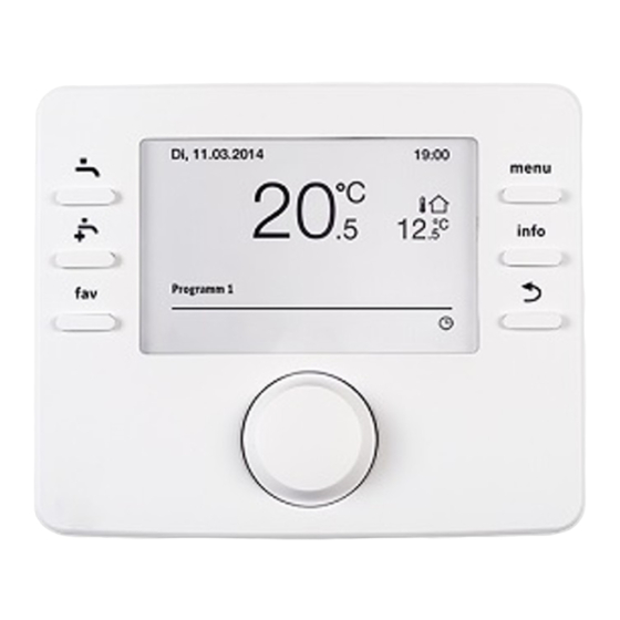
(no commands are executed). If no [6] Back key – switches to the previous menu item control element is actuated, the lighting turns [7] Selector off automatically. 6 720 817 986 (2015/07) HPC 400 VOGEL NOOT & CLIMATE CONTROL SYSTEMS... - Page 5 ▶ Press to activate the input field for selecting the heating circuit in the standard display (systems with at least two heating circuits only, Chapter 4.1, page 8). Table 2 Control elements HPC 400 6 720 817 986 (2015/07) VOGEL NOOT &...
- Page 6 Key lock When the key is displayed, this means that the key lock is enabled (page 10, Table 7). Table 3 Symbols on the standard display 6 720 817 986 (2015/07) HPC 400 VOGEL NOOT & CLIMATE CONTROL SYSTEMS...
- Page 7 Program 2 the times set. Heating mode in the displayed heating circuit active Setback mode in the displayed heating circuit active Table 3 Symbols on the standard display HPC 400 6 720 817 986 (2015/07) VOGEL NOOT & CLIMATE CONTROL SYSTEMS...
-
Page 8: Getting Started
The user interface controls the room temperature according to the active time program for the heating system. Table 5 Getting started – Activating operating modes 6 720 817 986 (2015/07) HPC 400 VOGEL NOOT & CLIMATE CONTROL SYSTEMS... -
Page 9: Changing The Room Temperature
The room temperature that is currently valid is shown in a pop-up window in the lower part of the display. 6 720 812 775-06.1O The user interface operates with the modified settings. Table 6 Getting started – Room temperature HPC 400 6 720 817 986 (2015/07) VOGEL NOOT & CLIMATE CONTROL SYSTEMS... -
Page 10: More Settings
DHW and DHW reduced operating modes. 6 720 811 136-10.1O If optimised mode is active, the temperature will not be changed. Table 7 Getting started – More settings 6 720 817 986 (2015/07) HPC 400 VOGEL NOOT & CLIMATE CONTROL SYSTEMS... - Page 11 ( Chapter 5.2.2, page 15). 6 720 815 237-14.1O Table 7 Getting started – More settings HPC 400 6 720 817 986 (2015/07) VOGEL NOOT & CLIMATE CONTROL SYSTEMS...
-
Page 12: Favourite Functions
▶ Turn and press the selector to select a function (Yes) or to cancel your selection (No). The changes are effective immediately. ▶ Press the Back key to close the menu. 6 720 811 136-15.1O Table 8 Getting started – Favourite functions 6 720 817 986 (2015/07) HPC 400 VOGEL NOOT & CLIMATE CONTROL SYSTEMS... -
Page 13: Working With The Main Menu
6 720 811 136-101.3O Fig. 3 Menu structure of the main menu Not available if Sweden or Finland is set as the country (for the contractor only). HPC 400 6 720 817 986 (2015/07) VOGEL NOOT & CLIMATE CONTROL SYSTEMS... -
Page 14: Main Menu Summary
Change general settings such as time, date, display contrast, etc. or restore settings saved by the contractor. Table 9 Main menu summary 1) Not available if Sweden or Finland is set as the country (for the contractor only). 6 720 817 986 (2015/07) HPC 400 VOGEL NOOT & CLIMATE CONTROL SYSTEMS... -
Page 15: Adapting Settings For Heating System Automatic
▶ Set switching times for a group of days, e.g. program. If you do not require heating overnight, speak to your Mon-Sun or Mon-Fri. contractor. He has access to additional settings for configuring setback mode. HPC 400 6 720 817 986 (2015/07) VOGEL NOOT &... - Page 16 The changes in this menu only affect the selected day of the week or the selected group of days. 6 720 815 237-28.1O Table 13 Adapting time program to suit individual preferences 6 720 817 986 (2015/07) HPC 400 VOGEL NOOT & CLIMATE CONTROL SYSTEMS...
- Page 17 The user interface operates with the modified settings. Table 13 Adapting time program to suit individual preferences The following table shows you how to change the names of heating circuits, for example. HPC 400 6 720 817 986 (2015/07) VOGEL NOOT &...
- Page 18 The cursor flashes in the place where the character <C was previously located. ▶ Press the Back key to exit the input process and to use the entered name. Table 14 Rename heating circuit 6 720 817 986 (2015/07) HPC 400 VOGEL NOOT &...
-
Page 19: Setting The Summer/Wintertime Changeover
2) When the outside temperature is adjusted, changes to the measured outside temperature are delayed and fluctuations reduced. HPC 400 6 720 817 986 (2015/07) VOGEL NOOT &... -
Page 20: Changing The Settings For Dhw Heating
Chapter 5.2.2 starting on page 15). The DHW temperatures set for the operating modes are valid in the time slots. 6 720 815 237-41.1O Table 19 Adapting the settings for DHW heating 6 720 817 986 (2015/07) HPC 400 VOGEL NOOT & CLIMATE CONTROL SYSTEMS... -
Page 21: Extra Dhw Heating
If the thermal disinfection temperature is not reached within the time set here, thermal disinfection is cancelled. The user interface then issues a fault in the display. Table 21 Settings for the thermal disinfection HPC 400 6 720 817 986 (2015/07) VOGEL NOOT &... -
Page 22: Dhw Alternating Operation Settings
6 720 811 136-29.1O The user interface operates with the modified settings. The DHW circulation pump is only in operation when DHW heating is active. Table 24 Adapting circulation settings 6 720 817 986 (2015/07) HPC 400 VOGEL NOOT & CLIMATE CONTROL SYSTEMS... -
Page 23: Settings For A Heated Swimming Pool
(gas, oil or wood heating Table 26 Time program for an additional device via a 3-way valve). This menu is only available if an auxiliary heater is installed in the heating system. HPC 400 6 720 817 986 (2015/07) VOGEL NOOT &... -
Page 24: Settings For Low-Noise Operation Of The Additional Device
Only the heating/cooling circuits and the will be active until. DHW system actually installed in the system are listed for selection. Table 28 Settings for holiday programs 6 720 817 986 (2015/07) HPC 400 VOGEL NOOT & CLIMATE CONTROL SYSTEMS... - Page 25 After this, the Holiday 1, 2, 3, 4 or 5, menu is displayed. Table 29 Setting up, interrupting or deleting a holiday program HPC 400 6 720 817 986 (2015/07) VOGEL NOOT &...
- Page 26 The holiday program applies again from this switching time onwards. 6 720 811 136-36.1O Table 29 Setting up, interrupting or deleting a holiday program 6 720 817 986 (2015/07) HPC 400 VOGEL NOOT & CLIMATE CONTROL SYSTEMS...
-
Page 27: Adapting The Settings To Hybrid Systems
X 0, 902 Example: • Cost of electricity: 24 ct/kWh • Cost of gas: 8 ct/kWh Energy:price ratio = (24 Cent/ 8 Cent) X 0, 902 = 2,7 HPC 400 6 720 817 986 (2015/07) VOGEL NOOT & CLIMATE CONTROL SYSTEMS... - Page 28 0.8 0.9 0.9 1.0 1.1 1.2 1.2 1.3 1.4 1.5 1.5 1.6 1.7 1.8 1.9 1.9 2.0 2.1 2.2 2.2 2.3 Table 31 Example: Cost weighting for electricity price – oil price 6 720 817 986 (2015/07) HPC 400 VOGEL NOOT &...
-
Page 29: Smart Grid Gain
Table 35 General settings 5.10 General settings No settings are lost in the event of a brief power failure or if the heat source is shut down for short periods of time. When the HPC 400 6 720 817 986 (2015/07) VOGEL NOOT &... - Page 30 0.7 °C higher than the user interface, increase the setting value by 0.7 K. ▶ Press the selector. The user interface operates with the modified settings. 6 720 817 986 (2015/07) HPC 400 VOGEL NOOT & CLIMATE CONTROL SYSTEMS...
-
Page 31: Calling Up Information About The System
Fig. 5 Menu structure of the info menu Only available if a temperature sensor or remote control is installed in the reference room of the corresponding heating circuit. HPC 400 6 720 817 986 (2015/07) VOGEL NOOT & CLIMATE CONTROL SYSTEMS... - Page 32 (Consumed energy > Total) and separately for each load. If two heat pumps are operated in a cascade, all of the menu items are shown separately for each heat pump. 6 720 817 986 (2015/07) HPC 400 VOGEL NOOT & CLIMATE CONTROL SYSTEMS...
- Page 33 Cumulated output for DHW heating produced Cooling output Cumulated output for cooling mode produced Pool output Cumulated output for swimming pool produced heating Table 42 Information on the total output produced HPC 400 6 720 817 986 (2015/07) VOGEL NOOT & CLIMATE CONTROL SYSTEMS...
- Page 34 The currently measured outside temperature is displayed in this menu. In addition, a diagram of the outside temperature profile for today and yesterday (from 00:00 to 24:00 in each case) is displayed here. 6 720 817 986 (2015/07) HPC 400 VOGEL NOOT & CLIMATE CONTROL SYSTEMS...
- Page 35 (0.1 ... 15.0) selected heating circuit (Heating, Idle, Table 47 System information Cooling) Table 47 System information 1) The energy supplier block is not normally used in Sweden. HPC 400 6 720 817 986 (2015/07) VOGEL NOOT & CLIMATE CONTROL SYSTEMS...
-
Page 36: Energy Saving Tips
“jaming” (blocking). If the circulation pump should by chance start 6 720 817 986 (2015/07) HPC 400 VOGEL NOOT & CLIMATE CONTROL SYSTEMS... - Page 37 Table 48 Eliminating "sensed" faults 1) See the operating instructions for the additional heat source for further information. HPC 400 6 720 817 986 (2015/07) VOGEL NOOT & CLIMATE CONTROL SYSTEMS...
-
Page 38: Removing A Displayed Fault
3064 heating circuit 4) A11 6004 No communication w. solar – ▶ Check that the user interface is module correctly seated in its wall bracket. Table 49 6 720 817 986 (2015/07) HPC 400 VOGEL NOOT & CLIMATE CONTROL SYSTEMS... - Page 39 Cause or fault description Test procedure/Cause Corrective measure 1001 – No BUS connection between HPC 400 ▶ Check that the user interface is and CR 10 or CR 10 H in the correctly seated in its wall bracket. corresponding heating circuit (A22: heating circuit 2, ..., A24: heating...
-
Page 40: Environment / Disposal
(except for Off). Environmental protection is a fundamental corporate strategy Frost protection of the Bosch Group. Depending on the selected frost protection, the heat pump will The quality of our products, their efficiency and environmental turn on when the outside and/or room temperature reaches safety are all of equal importance to us and all environmental below a certain set threshold. - Page 41 Temperature of an operating mode A temperature that is assigned to an operating mode. The temperature is adjustable. See the explanations on operating mode. HPC 400 6 720 817 986 (2015/07)
-
Page 42: Index
Internet ..............35 Temperature above 60 °C .......... 20 Connection ..............35 thermal disinfection ..........20 Login data ..............35 Password ............29, 35 Environment / disposal ..........40 Internet password ............29 Extra DHW ..............21 6 720 817 986 (2015/07) HPC 400... - Page 43 Smart grid ..............15 Used appliances ............40 Smart grid gain for DHW ..........29 Software version ............31 Solar system ..............3 Venting ..............36 Standard display ............29 displayed heating circuit ..........8 Weather-compensated control ........36 Symbols ..............4 HPC 400 6 720 817 986 (2015/07)
Need help?
Do you have a question about the HPC 400 and is the answer not in the manual?
Questions and answers