Bosch PROSPERO PRP-IM2C1A User Manual
Hide thumbs
Also See for PROSPERO PRP-IM2C1A:
- Installation manual (60 pages) ,
- Configuration manual (44 pages)
Table of Contents
Advertisement
Quick Links
Advertisement
Table of Contents

Related Manuals for Bosch PROSPERO PRP-IM2C1A


Summary of Contents for Bosch PROSPERO PRP-IM2C1A
- Page 1 PROSPERO PRP‑IM2C1A User manual...
-
Page 3: Table Of Contents
Table of contents | en Table of contents Safety Short information Equipment overview Front view Rear view Top view Accessories Installation Delivery condition Installation method Operation Maintenance Technical data Dimensions Bosch Security Systems B.V. 2024-10 | V1.00 | F.01U.429.437 User manual... -
Page 4: Safety
13. Use only the accessories/fittings specified by the manufacturer. Installation of any equipment should follow the manufacturer's instructions and should utilize the manufacturer's recommended mounting accessories. 2024-10 | V1.00 | F.01U.429.437 Bosch Security Systems B.V. User manual... - Page 5 To avoid electric shock, do not open the housing. Consult only qualified service personnel regarding maintenance matters. Warning! To prevent fire or electric shock hazard, do not expose the device to rain or moisture. Bosch Security Systems B.V. 2024-10 | V1.00 | F.01U.429.437 User manual...
- Page 6 Telephone Network Voltage (TNV) circuits. The LAN port contains a SELV circuit and the WAN port contains a TNV circuit. Some LAN and WAN ports use RJ-45 connectors. Always be careful when connecting cables. 2024-10 | V1.00 | F.01U.429.437 Bosch Security Systems B.V. User manual...
-
Page 7: Short Information
Power supply status and fault status indicators. – Affixing to the cabinet tray through the screw holes. – Compact design allows 3 modules to be installed side by side at a 1U rack height. Bosch Security Systems B.V. 2024-10 | V1.00 | F.01U.429.437 User manual... -
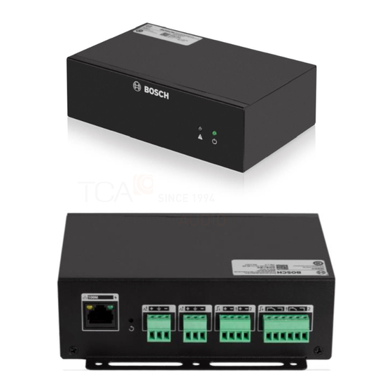
Page 8: Equipment Overview
| Equipment overview PROSPERO Equipment overview Front view Icon Indicator and control Description Fault warning Blinking yellow: indicator unauthorized Solid yellow: device failure Power indicator Green: On 2024-10 | V1.00 | F.01U.429.437 Bosch Security Systems B.V. User manual... -
Page 9: Rear View
Analog audio output Balanced line level connector audio output Control inputs 1-2 Dry contact control input Control output Relay control output connections 1-2 (normally closed/ normally open) Bosch Security Systems B.V. 2024-10 | V1.00 | F.01U.429.437 User manual... -
Page 10: Top View
| Equipment overview PROSPERO Top view Component Description (default configuration) 1, 2 Set screw hole Rack tray mounting screw holes 2024-10 | V1.00 | F.01U.429.437 Bosch Security Systems B.V. User manual... -
Page 11: Accessories
PROSPERO Accessories | en Accessories Quantity Components Interface Module, 2x2 control, 1x1 audio Safety and user information leaflet Terminal block (set) Bosch Security Systems B.V. 2024-10 | V1.00 | F.01U.429.437 User manual... -
Page 12: Installation
Secure the tray to the rack. Connect the network cable, audio cable, and control cable to the interface module. Notice! The cabinet trays need to be configured by the installer. 2024-10 | V1.00 | F.01U.429.437 Bosch Security Systems B.V. User manual... - Page 13 PROSPERO Installation | en 105 93 Figure 5.1: Fixing the module on the cabinet tray Description Screw Nut (female component of nut and bolt) Bosch Security Systems B.V. 2024-10 | V1.00 | F.01U.429.437 User manual...
- Page 14 | Installation PROSPERO Figure 5.2: Fixing a tray in a rack Figure 5.3: Network connection 2024-10 | V1.00 | F.01U.429.437 Bosch Security Systems B.V. User manual...
- Page 15 Use Ultra Category 5 network cables (or higher gauge). Figure 5.4: Analog audio input connection Use a three-pole balanced audio connection, paying attention to positive and negative polarity and grounding. Bosch Security Systems B.V. 2024-10 | V1.00 | F.01U.429.437 User manual...
- Page 16 Figure 5.5: Analog audio output connection Use a three-pole balanced audio connection, paying attention to positive and negative polarity and grounding. Figure 5.6: Analog audio 3-pole balanced connection Description Anodal Grounding Cathode 2024-10 | V1.00 | F.01U.429.437 Bosch Security Systems B.V. User manual...
- Page 17 PROSPERO Installation | en Figure 5.7: Analog audio 2-pole unbalanced connection Description Anodal Grounding Negative to ground jumper Bosch Security Systems B.V. 2024-10 | V1.00 | F.01U.429.437 User manual...
- Page 18 | Installation PROSPERO Figure 5.8: Dry contact control input connection Figure 5.9: Example of control input connection 2024-10 | V1.00 | F.01U.429.437 Bosch Security Systems B.V. User manual...
- Page 19 PROSPERO Installation | en Figure 5.10: Relay control output connection Normally open or normally closed options are available. 24 VDC LIGHT/ RELAY Figure 5.11: Example of control output connection Bosch Security Systems B.V. 2024-10 | V1.00 | F.01U.429.437 User manual...
-
Page 20: Operation
Press and hold the device reset button for 5 seconds, then release the device to reboot and return to the factory default configuration Icon Indicator and control Description Device reset button Restore factory default settings 2024-10 | V1.00 | F.01U.429.437 Bosch Security Systems B.V. User manual... -
Page 21: Maintenance
PROSPERO Maintenance | en Maintenance The modules do not require any special maintenance. To maintain cleanliness and a neat appearance, use a soft cloth to clean the module. Bosch Security Systems B.V. 2024-10 | V1.00 | F.01U.429.437 User manual... -
Page 22: Technical Data
<5 kΩ Contacts open >15 kΩ Control output contacts Interface 2x 3-pin Phoenix connector Principle Contact switch over (Relay SPDT) Maximum contact voltage (V) 30 V DC, 250 V AC Maximum contact current (A) 1 A 2024-10 | V1.00 | F.01U.429.437 Bosch Security Systems B.V. User manual... - Page 23 Weight 475 g Color (RAL) RAL 9017 Traffic black Environmental Operating temperature (°C) -5°C — 45°C Storage and transportation temperature (°C) -40°C — 70 C Operating relative humidity, non-condensing <95% (%%) Bosch Security Systems B.V. 2024-10 | V1.00 | F.01U.429.437 User manual...
-
Page 24: Dimensions
| Dimensions PROSPERO Dimensions Figure 9.1: Dimensions in mm 2024-10 | V1.00 | F.01U.429.437 Bosch Security Systems B.V. User manual... - Page 25 PROSPERO Dimensions | Bosch Security Systems B.V. 2024-10 | V1.00 | F.01U.429.437 User manual...
- Page 26 | Dimensions PROSPERO 2024-10 | V1.00 | F.01U.429.437 Bosch Security Systems B.V. User manual...
- Page 28 Bosch Security Systems B.V. Torenallee 49 5617 BA Eindhoven Netherlands www.boschsecurity.com © Bosch Security Systems B.V., 2024 Building solutions for a better life 202410241210...
Need help?
Do you have a question about the PROSPERO PRP-IM2C1A and is the answer not in the manual?
Questions and answers