
Subscribe to Our Youtube Channel
Related Manuals for SIGLENT SHS800X Series


Summary of Contents for SIGLENT SHS800X Series
- Page 1 SHS800X SHS1000X Handheld Digital Oscilloscope User Manual EN01A Dec,2021 WWW.SIGLENT.COM...
- Page 2 Declaration SIGLENT products are protected by patent law in and outside of P.R.C. SIGLENT reserves the right to modify or change parts of or all the specifications or pricing policies at company’s sole decision. Information in this publication replaces all previously corresponding material.
- Page 3 100 MHz bandwidth, 2-channel, 1 GSa/s Sample rate SHS807X 70 MHz bandwidth, 2-channel, 1 GSa/s Sample rate SHS1202X 200 MHz bandwidth, 2-channel, 1 GSa/s Sample rate SHS1102X 100 MHz bandwidth, 2-channel, 1 GSa/s Sample rate SHS1072X 70 MHz bandwidth, 2-channel, 1 GSa/s Sample rate WWW.SIGLENT.COM...
-
Page 4: Precautions For Operation
Therefore, appropriate measures must be taken, for example, protective masks and protective clothing must be worn. Safety Terms and Symbols The meaning of symbols symbol meaning symbol meaning Warning Power Switch Hazardous Voltage Equipment meeting double insulation or reinforced insulation EarthGround Indoor use only WWW.SIGLENT.COM... -
Page 5: Safety Operation Matters
Do not place the product on surface, vehicle, cabinet or tables that for reasons of weight or stability are unsuitable for this purpose. When installing the product and fastening it to the article or structures, always follow the manufacturer's installation instructions. If the WWW.SIGLENT.COM... - Page 6 It is forbidden to use this product when condensation has formed or may form inside or on the surface of this product. For example, when the oscilloscope moves from a cold environment to a warm environment, the penetration of water increases the risk of electric shock. WWW.SIGLENT.COM...
-
Page 7: Safety Transportation Matters
In order to facilitate the user to hold, SIGLENT Technology has installed a fabric handle on the oscilloscope. This handle cannot be used as a focus point to be fixed on transportation equipment, such as cranes, forklifts, trucks, etc. -
Page 8: Waste Disposal
Measurement, Control And Laboratory Use — Part 2-033: Particular Requirements For Hand-Held Multimeters For Domestic And Professional Use, Capable Of Measuring Mains Voltage General Care and Cleaning Care Do not store or leave the instrument in direct sunshine for extended periods of time. WWW.SIGLENT.COM... -
Page 9: Measurement Category
This measurement category is also called CATⅠ. CAT II: For measurements installed in buildings, such as junction boxes, circuit breakers, WWW.SIGLENT.COM... -
Page 10: Shs800X Measurement Category
Protecting Earth. CAT II 300Vrms Between BNC Signal and BNC GND. CAT II 300Vrms Between Signal and Scope(Probe input) Protecting Earth. CAT II 30Vrms Between Probe GND and Protecting Earth. CAT II 300Vrms Between Probe Signal and Probe GND. WWW.SIGLENT.COM... - Page 11 Risque de choc électrique ! Les masses de référence du SHS800X CH1 et CH2 sont connectées ensemble, connectées l'une d'elles à une tension supérieure à 30 Vrms et toucher l'autre peut entraîner des blessures. WWW.SIGLENT.COM...
-
Page 12: Shs1000X Measurement Category
Probe Input BNC Input INPUT A INPUT B CAT III 600V CAT III 300V /CAT II 1000V GND B GND A CAT III 600V CAT III 600V /CAT II 1000V /CAT II 1000V Protecting GND Measurement Category for SHS1000X Scope WWW.SIGLENT.COM... -
Page 13: Working Environment
This product is powered by mains conforming to installation (overvoltage) category II. WARNING Make sure that no overvoltage (such as that caused by thunderbolt) can reach the product, or else the operator might expose to danger of electric shock. Assurez-vous qu'aucune surtension (comme celle causée par la foudre) ne VIII WWW.SIGLENT.COM... -
Page 14: Ventilation Requirement
Inadequate ventilation may cause temperature increase which would damage the instrument. So please keep the instrument well ventilated during operation. Une ventilation inadéquate peut entraîner une augmentation de la température endommagerait l'instrument. Veuillez donc garder l'instrument bien ventilé pendant le fonctionnement. WWW.SIGLENT.COM... -
Page 15: Ac Power Requirement
To make the oscilloscope completely power off, unplug the instrument power cord from the AC socket and remove the battery from the scope. The battery should be removed from the scope when it is not to be used for an extended period of time. WWW.SIGLENT.COM... -
Page 16: Maintenance And Services
Adjustment, replacement of parts, maintenance and repair can only be performed by operators authorized by SIGLENT Technology. Safety-related parts can only be replaced with original parts. Safety tests must be carried out after replacing parts. -
Page 17: Document Overview
Search Introduce the oscilloscope search function Navigate Introduce waveform navigation function of the oscilloscope History Introduce how to use and set historical waveform functions. Meter Introduce how to use meter function. Recorder Introduce how to use recorder function. XXIV WWW.SIGLENT.COM... -
Page 18: Table Of Contents
Front Panel Overview ....................9 Side Panel Overview ....................10 Rear Panel Overview ....................11 Front Panel Function Overview ................12 Horizontal ......................12 Vertical ......................... 13 Trigger ........................ 14 Run Control ......................15 Universal Knob ....................16 Other Buttons ....................17 XXIX WWW.SIGLENT.COM... - Page 19 Trigger Source ......................55 Trigger Mode ......................56 Trigger Level ......................58 Trigger Coupling ....................... 59 Trigger Holdoff ......................60 Noise Rejection ......................61 Trigger Type ......................63 Edge Trigger ...................... 64 Slope Trigger ..................... 66 Pulse Trigger ...................... 68 WWW.SIGLENT.COM...
- Page 20 Math Operators....................... 120 Addition or Subtraction .................. 120 Multiplication and Division ................122 FFT Operation ....................123 Math Function Operation ..................129 Cursors ..........................134 X Cursors........................134 Y Cursors ........................134 Make Cursor Measurements ................. 136 Measure .......................... 138 XXXI WWW.SIGLENT.COM...
- Page 21 Do Self-Test ......................171 Screen Test ....................... 171 Keyboard Test....................172 LED Test ......................173 Screen Saver ......................174 Date/Time ....................... 175 Set Date/Time ....................175 Set Time Zone ....................176 Reference Position ....................177 Search ..........................178 Setting ........................178 XXXII WWW.SIGLENT.COM...
- Page 22 Meter ..........................184 DCV/ACV ........................186 Resistance ....................... 188 Diode ........................189 Continuity ........................ 190 Capacitance ......................191 DCI/ACI........................192 Recorder ......................... 194 Sample Logger ....................... 194 Measure Logger ...................... 199 Factory Setup ......................... 205 Troubleshooting ......................206 XXXIII WWW.SIGLENT.COM...
-
Page 23: Quick Start
. The contents of this chapter: General Inspection Appearance and Dimensions Prepare for Using Front Panel Overview Side Panel Overview Rear Panel Overview Front Panel Function Overview Help User Interface WWW.SIGLENT.COM... -
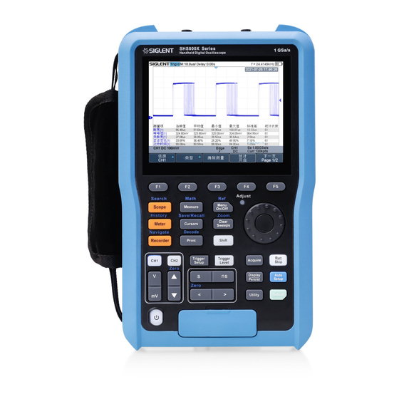
Page 24: Appearance And Dimensions
SHS800X&SHS1000X User Manual Appearance and Dimensions Figure 1 Front View Figure 2 Side view WWW.SIGLENT.COM... -
Page 25: Prepare For Using
Put the battery into the battery slot and close the battery cover, as shown in Figure 6. Lock the screws with the screwdriver, as shown in Figure 4, and then turn on the oscilloscope to check whether the battery is installed successfully. WWW.SIGLENT.COM... -
Page 26: Connect The Power Supply
When the oscilloscope is idle, the battery needs to be charged every 3 months . Connect the Power Supply The power requirements of the oscilloscope is 100-240 V, 50/60Hz. Please use the power cord provided to connect the oscilloscope to the power source. WWW.SIGLENT.COM... -
Page 27: Power-On Inspection
Function Inspection Press the Default button on the front panel to restore the instrument to its default configuration. Connect the ground alligator clip of the probe to the “Ground Terminal” WWW.SIGLENT.COM... - Page 28 Pour éviter les chocs électriques lors de l'utilisation de la sonde, veuillez vous assurer que le fil isolé de la sonde est en bon état et ne touchez pas la partie métallique de la sonde lorsque la sonde est connectée à une source haute tension WWW.SIGLENT.COM...
-
Page 29: Probe Compensation
“Perfectly compensated” in the figure above. Multimeter Meter Pen To avoid obtaining no measurements or unnecessary damage to the SHS800X/SHS1000X, you should use the right jack when measuring current, voltage and other measurement. WWW.SIGLENT.COM... -
Page 30: Front Panel Overview
SHS800X&SHS1000X User Manual Front Panel Overview Figure 9 Scope Front Panel Overview Description Description Power Button Universal Knob Vertical Control Trigger Control Dual Function Button Horizontal Control Menu Soft key Single Function Button LCD Display Multimeter Input Analog Channel Input WWW.SIGLENT.COM... -
Page 31: Side Panel Overview
Supplies a 0-5 V, 1 kHz square wave for compensating the probes. USB Host Connect the USB host ports to USB storage devices for data transfer. USB Device The oscilloscope support SCPI remote control commands, user can control the oscilloscope through this interface. Adapter Power Input WWW.SIGLENT.COM... -
Page 32: Rear Panel Overview
Figure 11 Scope Rear Panel Overview Battery Cover Supporting Leg Adjust the supporting leg properly to use them as stands to tilt the oscilloscope upwards for stable placement of the oscilloscope as well as better operation and observation. Handle WWW.SIGLENT.COM... -
Page 33: Front Panel Function Overview
During the modification, waveforms of all the channels will be displayed in expanded or compressed mode and the time base message at the upper-left side of the screen would change accordingly. WWW.SIGLENT.COM... -
Page 34: Vertical
Vertical Scale Button: adjust the vertical scale of the current channel. Press mV to decrease the scale and press V to increase. During the modification, the amplitude of the waveform would enlarge or reduce and the scale information in the channel setup box would change accordingly. WWW.SIGLENT.COM... -
Page 35: Trigger
: press the button and then turn the Universal Knob to adjust the trigger level. During the modification, the trigger level line would move up and down. Press down the Universal Knob to quickly reset the trigger level to center of the waveform. WWW.SIGLENT.COM... -
Page 36: Run Control
The oscilloscope will automatically adjust the vertical scale, horizontal time base and trigger mode according to the input signal to realize optimum waveform display. Press the button to reset the oscilloscope to user default setup. WWW.SIGLENT.COM... -
Page 37: Universal Knob
Choose file or directory or input filename. After having entered the file system, turn the Universal Knob to select the desired file or directory. When inputting filename, turn the Universal Knob to select the desired character and the push the knob to confirm. WWW.SIGLENT.COM... -
Page 38: Other Buttons
Press the button to turn on/off menu display. Press Shift and this button to enter the REF function menu. Clears the data or display in multiple sweeps, including display persistence, measurement statistics, average sweeps and Pass/Fail statistics. Press Shift and this button to enter zoom mode. WWW.SIGLENT.COM... - Page 39 Press the button to enter the DISPLAY menu. The second press turn on Persist, press the button again to turn off Persist. Press to enter the UTILITY function menu to look at the system status, do self-calibration, set the sound, language and so on. WWW.SIGLENT.COM...
-
Page 40: Help
The oscilloscope has an on line help function that supplies multi-language help information. You can access the help function by pressing any button for 2 seconds and a help window will explain the function. Also all of the submenus include help information. Figure 12 Help Message WWW.SIGLENT.COM... -
Page 41: User Interface
SHS800X&SHS1000X User Manual User Interface Figure 13 User Interface Product Logo SIGLENT is the registered trademark of SIGLENT TECHNOLOGIES CO., LTD. Acquisition Status Available trigger status includes Arm, Ready, Trig’d, Auto, Stop, FStop, Roll. Horizontal Time Base Represent the time per grid on the horizontal axis on the screen. - Page 42 Different channels are marked by different colors and the color of the waveform complies with the color of the channel. 15. Menu Display the corresponding function menu of the selected button. Press the corresponding soft key to set the oscilloscope. WWW.SIGLENT.COM...
-
Page 43: Vertical System
This chapter introduces how to set the vertical system of the oscilloscope. The contents of this chapter: Enable the Channel Adjust Scale Vertical Position Coupling Bandwidth Limit Probe Unit Deskew Invert Trace Visible/Hidden WWW.SIGLENT.COM... -
Page 44: Enable The Channel
After the channel is turned on, modify the parameters such as the vertical scale, the horizontal time base and the trigger mode according to the input signal to make the waveform display easy to observe and measure. Note: to turn off the channel, press the channel button twice. WWW.SIGLENT.COM... -
Page 45: Adjust Scale
The adjustable range of the vertical scale is related to the probing ratio currently set. By default, the probe attenuation factor is 1X and the adjustable range of the vertical scale is from 2 mV/div to 100 V/div. WWW.SIGLENT.COM... -
Page 46: Vertical Position
Universal Knob to select the desired coupling mode. The default setup is DC. The current coupling mode is displayed in the channel information bar at the bottom of the screen. You can also press the Coupling softkey continuously to switch the coupling mode. WWW.SIGLENT.COM... -
Page 47: Bandwidth Limit
The table shows the probe attenuation factor Menu Attenuation Factor 0.1X 0.1 : 1 0.2X 0.2 : 1 0.5X 0.5 : 1 1 : 1 2 : 1 … … 5000X 5000 : 1 10000X 10000 : 1 WWW.SIGLENT.COM... -
Page 48: Unit
Press the Deskew softkey. Then turn the Universal Knob to change deskew. Invert When Invert is set to On, the voltage values of the displayed waveform are inverted. Invert affects how a channel is displayed while it keeps the trigger WWW.SIGLENT.COM... -
Page 49: Trace Visible/Hidden
Press CH1 button on the front panel to enter the CH1 function menu. Press the Next Page softkey to enter the third page of the CH1 function menu. Press the Trace softkey to show or hide the channel waveform Trace Visible Trace Hidden WWW.SIGLENT.COM... -
Page 50: Horizontal System
SHS800X&SHS1000X User Manual Horizontal System This chapter introduces how to set the horizontal system of the oscilloscope. The contents of this chapter: Horizontal Scale Horizontal Delay Roll Mode Zoom Mode WWW.SIGLENT.COM... -
Page 51: Horizontal Scale
The Horizontal Scale button works (in the Normal time mode) while acquisitions are running or when they are stopped. When in run mode, adjust the horizontal scale knob to change the sample rate. When stopped, adjust the horizontal scale knob to zoom in the acquired data. WWW.SIGLENT.COM... -
Page 52: Horizontal Delay
When changing the horizontal delay, the delay time displayed in the information bar at the top of the screen changes in real time, indicating the distance between the time reference point and the trigger point. The available delay range depends on the selected time/div and memory depth. WWW.SIGLENT.COM... -
Page 53: Roll Mode
Roll mode, press the Run/Stop button again. Use Roll mode on low- frequency waveforms to yield a display much like a strip chart recorder. It allows the waveform to roll across the display. WWW.SIGLENT.COM... -
Page 54: Zoom Mode
This border area in the normal window is zoomed to the lower half. To change the time base for the Zoom window, press the Horizontal Scale button. The Horizontal Scale button controls the size of the border area. The Horizontal WWW.SIGLENT.COM... - Page 55 Position button. Negative delay values indicate you're looking at a portion of the waveform before the trigger event, and positive values indicate you're looking at the waveform after the trigger event. To change the time base of the normal window, turn off Zoom; then press the Horizontal Scale button. WWW.SIGLENT.COM...
-
Page 56: Acquisition System
This chapter introduces how to use the acquisition control and set the sampling system of the oscilloscope. The contents of this chapter: Overview Memory Depth Sampling Mode Interpolation Method Acquisition Mode Horizontal Format Sequence Mode WWW.SIGLENT.COM... -
Page 57: Overview
The actual sample rate is displayed in the information area at the bottom right corner of the screen. The effect of low sampling rate on the waveform: Waveform Distortion: when the sample rate is too low, some waveform details are lost and the waveform displayed is quite different from the actual signal. WWW.SIGLENT.COM... -
Page 58: Bandwidth And Sample Rate
= 2f according to the sampling theory. However, the theory assumes that there are no frequency components above f in this case) in the system, which means that it requires a system with an ideal brick wall frequency response. WWW.SIGLENT.COM... - Page 59 500 MHz and below, the system has a Gaussian frequency response. Therefore, the sampling frequency of the oscilloscope should be four or more times the bandwidth frequency: f = 4fBW. In this way, there is less aliasing, and the components in the aliasing area are attenuated a lot. WWW.SIGLENT.COM...
-
Page 60: Memory Depth
Single Channel Mode Dual Channel Mode 120k 1.2M 600k The relation of memory depth, sample rate, and waveform length fulfills the equation below: Memory depth = sample rate (Sa/s) × waveform length (s/div × div) WWW.SIGLENT.COM... -
Page 61: Sampling Mode
1GSa/s. Press the Run/Stop button to stop the sample, and the oscilloscope will hold the last display. At this point, you can still use the vertical control and horizontal control to pan and zoom the waveform. WWW.SIGLENT.COM... -
Page 62: Interpolation Method
This method bending signal waveform, and make it produce a more realistic regular shape than pure square wave and pulse. When the sampling frequency is 3 to 5 times the bandwidth frequency of the system. Recommended Sinx/s interpolation method. WWW.SIGLENT.COM... - Page 63 SHS800X&SHS1000X User Manual Figure 15 Display Type Set to Dots Figure 16 x Interpolation WWW.SIGLENT.COM...
- Page 64 SHS800X&SHS1000X User Manual Figure 17 Sinx/x Interpolation WWW.SIGLENT.COM...
-
Page 65: Acquisition Mode
In this mode, the oscilloscope samples the signal at equal time intervals to rebuild the waveform. For most of the waveforms, the best display effect can be obtained using this mode. It is the default acquisition mode. Figure 18 Acquisition System WWW.SIGLENT.COM... -
Page 66: Peak Detect
In this mode, signal confusion can be prevented but the noise displayed would be larger. In this mode, the oscilloscope can display all the pulses with pulse widths at least as wide as the sample period. Figure 19 Pulse With 0.1% Duty, Normal Mode WWW.SIGLENT.COM... -
Page 67: Average
The available range of averages is from 4 to 1024 and the default is 16. When Average mode is selected, press Averages and turn the Universal knob or press the softkey continually to set the desired average time. WWW.SIGLENT.COM... - Page 68 SHS800X&SHS1000X User Manual Figure 21 With Random Noise, Normal Mode Figure 22 With Random Noise, Average Mode WWW.SIGLENT.COM...
-
Page 69: Eres
This mode limits the oscilloscope's real- time bandwidth because it effectively acts like a low- pass filter. Note: “Average” and “ERES” mode use different averaging methods. The former uses “Waveform Average” and the latter uses “Dot Average”. WWW.SIGLENT.COM... -
Page 70: Horizontal Format
According to sinθ=A/B or C/D (wherein, θ is the phase deviation angle between the two channels and the definitions of A, B, C, and D are as shown in the figure above), the phase deviation angle is obtained, that is: θ=±arcsin (A/B) or ±arcsin (C/D) WWW.SIGLENT.COM... - Page 71 The X-Y function can be used to measure the phase deviation that occurred when the signal under test passes through a circuit network. Connect the oscilloscope to the circuit to monitor the input and output signals of the circuit. WWW.SIGLENT.COM...
-
Page 72: Sequence Mode
Figure 23 SEQUENCE Function Menu Press the Max. Segments softkey; and then turn the Universal Knob to select the desired value. Do the following steps to replay the sequence waveform under history mode: Press the Shift and Meter button to enable HISTORY function. WWW.SIGLENT.COM... - Page 73 Press the Frame No. softkey; and then turn the Universal Knob to select the frame to display. Press the softkey to replay the waveform from the current frame to 1. Press the softkey to stop replay. Press the softkey to replay the waveform from the current frame to the last frame. WWW.SIGLENT.COM...
-
Page 74: Trigger
These trigger types are edge, slope, pulse, video, window, interval, dropout, runt, pattern and serial trigger. This chapter will mainly introduce all these trigger functions mentioned above in detail and tell you how to set the trigger conditions to capture the desired waveform. WWW.SIGLENT.COM... - Page 75 SHS800X&SHS1000X User Manual The contents of this chapter: Trigger Source Trigger Mode Trigger Level Trigger Coupling Trigger Holdoff Noise Rejection Trigger Type WWW.SIGLENT.COM...
-
Page 76: Trigger Source
Analog channel input: Signals input from analog channels can all be used as the trigger source. Note: to select stable channel waveform as the trigger source to stabilize the display. WWW.SIGLENT.COM... -
Page 77: Trigger Mode
In the Single trigger mode, the oscilloscope waits for a trigger, displays the waveform when the trigger condition is met, and stops. The Single trigger mode is appropriate when: WWW.SIGLENT.COM... - Page 78 In the Force trigger mode, when the trigger condition is not met, it will be force triggered after the frame is acquired. The trigger status in the upper left corner of the screen will be displayed as "FStop". WWW.SIGLENT.COM...
-
Page 79: Trigger Level
If AC coupling is used, pushing the Universal Knob sets the trigger level to about 0 V. The position of the trigger level for the analog channel is indicated by the trigger level icon (if the analog channel is on) at the left side of the display. WWW.SIGLENT.COM... -
Page 80: Trigger Coupling
Use LF Reject coupling to get a stable edge trigger when your waveform has low frequency noise. HF Reject: reject the high frequency components higher 1.2 MHz) Note: trigger coupling has nothing to do with the channel coupling. WWW.SIGLENT.COM... -
Page 81: Trigger Holdoff
Press the Trigger Setup button to enter the TRIGGER function menu. The default trigger type is edge. Press the Holdoff Close softkey; and then turn the Universal Knob to set the desired holdoff time. Note: adjust the time scale and horizontal position will not affect the holdoff time. WWW.SIGLENT.COM... -
Page 82: Noise Rejection
Press the Trigger Setup button on the front panel, and then press the Noise Reject softkey continually to set the option to On or Off to turn on or off the noise rejection function. Figure 25 Turn off the Noise Reject WWW.SIGLENT.COM... - Page 83 Connect a signal to the oscilloscope and obtain a stable display. Remove the noise from the trigger path by setting trigger coupling to LF Reject, HF Reject or turning on Noise Reject. Set the Acquisition option to Average to reduce noise on the displayed waveform. WWW.SIGLENT.COM...
-
Page 84: Trigger Type
The oscilloscope provides abundant advanced trigger functions, including various serial bus triggers. Edge trigger Slope trigger Pulse trigger Video trigger Window trigger Interval trigger Dropout trigger Runt trigger Pattern trigger WWW.SIGLENT.COM... -
Page 85: Edge Trigger
(rising, falling or alternating), and then press down the knob to confirm. The current trigger slope is displayed at the bottom of the screen. Press the Trigger Level button and turn the Universal Knob to adjust the trigger level to obtain stable trigger. WWW.SIGLENT.COM... - Page 86 Holdoff, coupling and noise reject can be set in edge trigger, see the sections “Trigger Holdoff”, "Trigger Coupling" and "Noise Rejection" for details. Note: Press the Auto Setup button will set the trigger type to Edge and slope to rising. WWW.SIGLENT.COM...
-
Page 87: Slope Trigger
Press Lower Upper softkey to select the Lower or Upper trigger level; then press the Trigger Level button and turn the Universal Knob to adjust the position. The lower trigger level cannot be upper than the upper trigger level. WWW.SIGLENT.COM... - Page 88 Coupling and noise reject can be set in slope trigger, see the sections "Trigger Coupling" and "Noise Rejection" for details. WWW.SIGLENT.COM...
-
Page 89: Pulse Trigger
>= (greater than a time value): trigger when the input signal's positive or negative pulse time is greater than the specified time value. For example, for a positive pulse, if you set t (pulse real width) ≥ 100ns, the waveform will trigger. WWW.SIGLENT.COM... - Page 90 Figure 29 Pulse Trigger Coupling and noise reject can be set in pulse trigger, see the sections "Trigger Coupling" and "Noise Rejection" for details. WWW.SIGLENT.COM...
-
Page 91: Video Trigger
The table below shows the parameters of the Custom video trigger. Frame Rate 25Hz, 30Hz, 50Hz, 60Hz Of Lines 300~2000 Of Fields 1, 2, 3, 4 Interlace 1:1, 2:1, 4:1, 8:1 Trigger Position Line Field (line value)/1 (line value)/2 (line value)/3 (line value)/4 (line value)/5 (line value)/6 WWW.SIGLENT.COM... - Page 92 Press the Standard softkey; turn the Universal Knob to select NTSC, and press the knob to confirm. Press the Sync softkey and set the option to Select; press the Line softkey and WWW.SIGLENT.COM...
- Page 93 Press the Sync softkey to enter the TRIG ON menu to set the line and field. Press the Type softkey to select Select or Any. If the Type option set to Select, press the Line softkey; turn the Universal WWW.SIGLENT.COM...
- Page 94 SHS800X&SHS1000X User Manual Knob to select the desired value. Press the Field softkey; turn the Universal Knob to select the desired value. WWW.SIGLENT.COM...
-
Page 95: Window Trigger
Press the Source softkey; turn the Universal Knob to select CH1 or CH2 as the trigger source. Press the Window Type softkey to select Absolute. Press the Lower Upper softkey to select Lower or Upper trigger level; then press the Trigger Level button and turn the Universal Knob to adjust the WWW.SIGLENT.COM... - Page 96 Press the Source softkey; turn the Universal Knob to select CH1 or CH2 as the trigger source. Press the Window Type softkey to select Relative. Press the Center Delta softkey to select Center or Delta trigger level mode; then press the Trigger Level button and turn the Universal Knob to adjust the position. WWW.SIGLENT.COM...
- Page 97 SHS800X&SHS1000X User Manual Figure 32 Relative Window Trigger Coupling and noise reject can be set in Window trigger, see the sections "Trigger Coupling" and "Noise Rejection" for details. WWW.SIGLENT.COM...
-
Page 98: Interval Trigger
Press the Time Setting softkey (<=, >=, [--,--],--][--), turn the Universal Knob to select the desired value. WWW.SIGLENT.COM... - Page 99 SHS800X&SHS1000X User Manual Figure 33 Interval Trigger Coupling and noise reject can be set in interval trigger, see the sections "Trigger Coupling" and "Noise Rejection" for details. WWW.SIGLENT.COM...
-
Page 100: Dropout Trigger
Select channel with signal input as trigger source to obtain stable trigger. Press the Slope softkey to select rising or falling edge. Press the OverTime Type softkey to select Edge. Press the Time softkey; turn the Universal Knob to select the desired value. WWW.SIGLENT.COM... - Page 101 Press the Source softkey; turn the Universal Knob to select CH1 or CH2 as the trigger source. Press the Slope softkey to select rising or falling edge. Press the OverTime Type softkey to select State. Press the Time softkey; turn the Universal Knob to select the desired value. WWW.SIGLENT.COM...
- Page 102 SHS800X&SHS1000X User Manual Figure 35 State Dropout Trigger Coupling and noise reject can be set in dropout trigger, see the sections "Trigger Coupling" and "Noise Rejection" for details. WWW.SIGLENT.COM...
-
Page 103: Runt Trigger
Press the Next Page softkey to enter the second page of the TRIGGER system function menu. Press the Lower Upper softkey to select Lower or Upper trigger level, and press the Trigger Level button and turn the Universal Knob to set the position. WWW.SIGLENT.COM... - Page 104 SHS800X&SHS1000X User Manual Figure 36 Runt Trigger Coupling and noise reject can be set in runt trigger, see the sections "Trigger Coupling" and "Noise Rejection" for details. WWW.SIGLENT.COM...
-
Page 105: Pattern Trigger
However, if all channels in the pattern are set to Don’t care, the oscilloscope will not trigger. Adjust the trigger level for the selected analog channel by pressing the Trigger Level button and turning the Universal Knob. Don’t care doesn’t WWW.SIGLENT.COM... - Page 106 Press the Holdoff Close softkey to turn on the Holdoff function; then turn the Universal Knob to select the desired value. Figure 37 Pattern Trigger Holdoff can be set in pattern trigger, see the sections "Trigger Holdoff" for details. WWW.SIGLENT.COM...
-
Page 107: Serial Trigger And Decode
This chapter introduces the method of triggering and decoding these serial signals in details. The contents of this chapter: I2C Trigger and Decode SPI Trigger and Decode UART Trigger and Decode CAN Trigger and Decode LIN Trigger and Decode WWW.SIGLENT.COM... -
Page 108: I2C Trigger And Serial Decode
Universal Knob. The threshold voltage level is for decoding, and it will be regard as the trigger voltage level when set the trigger type to serial. (Tips: SDA should keep stable during the whole high clock cycle, otherwise it WWW.SIGLENT.COM... -
Page 109: I2C Trigger
Limit Range softkey to set the qualifier and Data1 softkey to set the data’s value. If EEPROM’s data is greater(less, equal) than Data1, the oscilloscope will be triggered at the edge of ACK bit behind Data byte. The Data byte musts don’t have to follow the EEPROM. WWW.SIGLENT.COM... - Page 110 10 Address & Data — the oscilloscope will be triggered when the following conditions are satisfied. The address’s length must be 10 bits and the address’s value is the same as set value. If you have set either Data1’s or Data2’s value, and the signal has a data WWW.SIGLENT.COM...
- Page 111 Press the Limit Range softkey to set the qualifier (=, < or >). Press the Data1 softkey and set its value by turning the Universal Knob. If you select 7 Addr & Data or 10 Addr & Data condition: WWW.SIGLENT.COM...
- Page 112 If you select the Data Length condition: Press the Address to set the SDA address length 7bit or 10 bit. Press the Byte Length softkey and set the byte length by Universal Knob. The range of the Byte Length is 1 to 12. WWW.SIGLENT.COM...
-
Page 113: I2C Serial Decode
The data value is displayed in white. "~A" after a data or address bits indicates no acknowledgement. For example, DB~A. Indicates there is not enough space on the display to show the complete content of a frame, and some content is hidden. WWW.SIGLENT.COM... - Page 114 Time — the horizontal displacement between current frame and trigger position. Address — the address of a frame. R/W — the type of a frame (write or read). Data — the value of data. Figure 42 I2C Decode List Display WWW.SIGLENT.COM...
-
Page 115: Spi Trigger And Serial Decode
Press the Threshold softkey to set the SPI MISO signal’s threshold voltage level by Universal Knob. The threshold voltage level is for decoding, and it will be regard as the trigger voltage level when set the trigger type to serial. Press the softkey to return previous menu. WWW.SIGLENT.COM... - Page 116 In the SPI trigger signal menu, set the source and threshold of CLK, MISO signals. Set the CS type to Clock Timeout, the clock idle time between frames is T3, the clock period is T1, then set the timeout to a value between T1 and T3: WWW.SIGLENT.COM...
- Page 117 SHS800X&SHS1000X User Manual If the data width is set to be greater than 8 bits (such as 16 bits), the clock idle time between 8-bit data packets T2, and then set the timeout time to a value between T1/2+T2 and T3. WWW.SIGLENT.COM...
- Page 118 SHS800X&SHS1000X User Manual WWW.SIGLENT.COM...
-
Page 119: Spi Trigger
High voltage level Bit Value Low voltage level Don’t care the voltage level Table 3 Menu Explanations of the SPI Bit value Press the Next Page softkey. Press the Bit Order softkey to set the bit order (MSB or LSB). WWW.SIGLENT.COM... -
Page 120: Spi Serial Decode
MISO — the decoding result of “Master-In, Slave-Out” line. MOSI —the decoding result of “Master-Out, Slave-In” line. Indicates there is not enough space on the display to show the complete content of a frame, and some content is hidden. WWW.SIGLENT.COM... - Page 121 The lists of decoding result: Time — the horizontal displacement between current frame and trigger position. MISO — the decoding result of “Master-In, Slave-Out” line. MOSI —the decoding result of “Master-Out, Slave-In” line. Figure 49 SPI Decode List Display WWW.SIGLENT.COM...
-
Page 122: Uart Trigger And Serial Decode
Custom and turn the Universal Knob to set the desired baud rate. 10. Press the Data Length softkey and set byte bits (5-8) by Universal Knob. 11. Press the Parity Check softkey to set the type of parity check (Even, Odd, Mark, Space or None). WWW.SIGLENT.COM... - Page 123 12. Press the Stop Bit softkey to set the length of stop bit (1, 1.5 or 2 bits). 13. Press the Next Page softkey. 14. Press the Bit Order softkey to select the bit order (LSB or MSB). 15. Press the Idle Level softkey to set the idle level (LOW or HIGH). WWW.SIGLENT.COM...
-
Page 124: Uart Trigger
Press the Value softkey to set data’s value. Data’s value is in range of 0x00 to 0xff. ERROR — if the parity check has been set, and the bit of parity check is error, the oscilloscope will be triggered. WWW.SIGLENT.COM... -
Page 125: Uart Serial Decode
TX — the decoding result of the data transmitted. Indicates there is not enough space on the display to show the complete content of a frame, and some content is hidden. Figure 53 UART Decode Bus Display WWW.SIGLENT.COM... - Page 126 RX — the receiving channel. TX — the transmitting channel. RX Err— Parity error or unknown error in the data received. TX Err— Parity error or unknown error in the data transmitted. Figure 54 UART Decode List Display WWW.SIGLENT.COM...
-
Page 127: Can Trigger And Serial Decode
The baud rate can be set as predefined value (from 5kb/s to 1Mb/s) or custom value (from 5kb/s to 1Mb/s). If the desired baud rate is not listed, press Baud and select custom option, press the Custom and turn the Universal Knob to set the desired baud rate. WWW.SIGLENT.COM... -
Page 128: Can Trigger
Press the Curr ID Byte softkey and use Universal Knob to select the byte that you want to modify. Press the ID softkey and set the ID’s value by Universal Knob. Press the Data softkey and set the value of the first byte by Universal Knob. WWW.SIGLENT.COM... -
Page 129: Can Serial Decode
Data field is displayed in frame CRC field is displayed in frame Indicates there is not enough space on the display to show complete content of a frame and some content is hidden. Figure 56 CAN Decode Bus Display WWW.SIGLENT.COM... - Page 130 (11 bits or 27 bits). Length — the length of data field. Data — the value of data field. CRC — the value of CRC (Cyclic Redundancy Check) field. ACK — Acknowledgment bit. Figure 57 CAN Decode List Displa WWW.SIGLENT.COM...
-
Page 131: Lin Trigger And Serial Decode
Press the Baud softkey to set baud rate. The baud rate can be set as predefined value. If the desired baud rate is not listed, select Custom option, press the Custom and turn the Universal Knob to set the desired baud rate. WWW.SIGLENT.COM... -
Page 132: Lin Trigger
Press the ID softkey and set its value by turning the Universal Knob. Press the DATA1 softkey and set its value by turning the Universal Knob. Press the DATA2 softkey and set its value by turning the Universal Knob. WWW.SIGLENT.COM... -
Page 133: Lin Serial Decode
Data Length is displayed in frame Data Field is displayed in frame. Checksum Field is displayed in frame. Indicates there is not enough space on the display to show complete content of a frame and some content is hidden. WWW.SIGLENT.COM... - Page 134 Data Length — the length of Data Field. ID Parity — the two check bits of Protected Identifier Field. Data — the value of Data Field. Checksum— the value of Checksum Field. Figure 60 LIN Decode List Display WWW.SIGLENT.COM...
-
Page 135: Reference Waveform
All reference waveforms can be displayed at a time. The contents of this chapter: Save REF Waveform to Internal Memory Display REF Waveform Adjust REF Waveform Clear REF Waveform WWW.SIGLENT.COM... -
Page 136: Save Ref Waveform To Internal Memory
Press the Location softkey; then, turn the Universal Knob to select the REF waveform that you want to display. Press the Display softkey to select On to display the REF waveform on the screen. Only saved location can be displayed. The oscilloscope can display all reference waveforms at the same time. WWW.SIGLENT.COM... -
Page 137: Adjust Ref Waveform
The vertical scale and position information display at the middle of the screen. The initial values display at the middle of the screen is the setup when the reference waveform is saved. Figure 61 Reference Waveform WWW.SIGLENT.COM... -
Page 138: Clear Ref Waveform
To clear the appointed reference waveform, you can save a new reference waveform to the same location to cover it. Or follow the Shift + Cursors → Recall → Type and select Security Erase to clear the stored waveform. WWW.SIGLENT.COM... -
Page 139: Math
The contents of this chapter: Units for Math Waveforms Math Operators Note: if the analog channel or the math function is cut off (waveforms do not display on the screen completely), the resulting math will also be cut off. WWW.SIGLENT.COM... -
Page 140: Units For Math Waveforms
V, A multiplication (*) 2, A 2 or W ∧ ∧ division (/) None, V*A^-1 or V^-1*A dBVrms, Vrms, dBm, dBArms, Arms differential (d/dt) V*S^-1 or A*S^-1 integral (∫dt) Wb, C square root ( ) 1/2 or A ∧ ∧ WWW.SIGLENT.COM... -
Page 141: Math Operators
Subtraction can be applied between analog channels. Press the Operator softkey and then turn the Universal Knob to select + or - to make addition or subtraction operation. The resulting math waveform is displayed in white and labeled with “M”. WWW.SIGLENT.COM... - Page 142 SHS800X&SHS1000X User Manual Figure 62 C1+C2 Waveform If you want to invert the math waveform, press the Invert button and set the option to On to invert the display of the math waveform. WWW.SIGLENT.COM...
-
Page 143: Multiplication And Division
The resulting math waveform is displayed in white and labeled with “M”. Figure 63 C1*C2 Waveform If you want to invert the math waveform, press the Invert button and set the option to On to invert the display of the math waveform. WWW.SIGLENT.COM... -
Page 144: Fft Operation
Spectral leakage can be considerably decreased when a window function is used. The oscilloscope provides five windows (Rectangle, Blackman, Hanning, Hamming and Flattop) which have different characteristics and are applicable to measure different waveforms. You need to select the window function according to different waveforms WWW.SIGLENT.COM... - Page 145 Press the Ref Level softkey, and then turn the Universal Knob to select the desired vertical FFT offset. Press the Unit softkey to select the unit of vertical axis. The vertical axis units can be dBVrms, dBm, Vrms or dBArms, Arms, which use a WWW.SIGLENT.COM...
- Page 146 Amplitude on both sides. Only when the difference is greater than the peak value of peak offset can the peak value be determined. Markers: Customize the marker locations on the FFT waveform based on search configuration. WWW.SIGLENT.COM...
- Page 147 Show Frequency softkey to show the frequency value of the markers, and press the Show Delta softkey to show the delta amplitude between markers. The following figure shows the FFT waveform displayed on the split screen and the peak tool is turned on: WWW.SIGLENT.COM...
- Page 148 Use the Y1 and Y2 cursors to measure amplitude in dB and difference in amplitude (ΔY). You can find the frequency value at the first occurrence of the waveform maximum by using the X at Max Y measurement. Note: please refer to the cursors chapter to obtain the method of using cursors. WWW.SIGLENT.COM...
- Page 149 SHS800X&SHS1000X User Manual WWW.SIGLENT.COM...
-
Page 150: Math Function Operation
= voltage value of data point i = data point index dx = point- to- point time difference The dx option under d/dt math function operation menu indicates data points. The minimum value is 4, and the unit is points. WWW.SIGLENT.COM... - Page 151 You can use differentiate to measure the instantaneous slope of a waveform. For example, the slew rate of an operational amplifier may be measured using the differentiate function Note: Because differentiation is very sensitive to noise, it is helpful to set acquisition mode to Average. WWW.SIGLENT.COM...
- Page 152 Small DC offset in the integrate function input (or even small oscilloscope calibration errors) can cause the integrate function output to "ramp" up or down. This DC offset correction lets you level the integrate waveform. WWW.SIGLENT.COM...
- Page 153 SHS800X&SHS1000X User Manual Figure 74 Integral without Offset Figure 75 Integral with Offset WWW.SIGLENT.COM...
- Page 154 SHS800X&SHS1000X User Manual Square Root Square root ( ) calculates the square root of the selected source. Where the transform is undefined for a particular input, holes (zero values) appear in the function output. Figure 76 Square Root WWW.SIGLENT.COM...
-
Page 155: Cursors
Y1 cursor is the top (default position) horizontal dotted line; it can be moved to any vertical place of the screen. Y2 cursor is the down (default position) horizontal dotted line; it can be moved to any vertical place of the screen. WWW.SIGLENT.COM... - Page 156 Y1 and Y2 (△Y). When set cursor type to Y2-Y1, use Universal Knob will move the Y1 and Y2 cursors together. The value under the menu option is the difference between the Y1 and Y2 cursors. WWW.SIGLENT.COM...
-
Page 157: Make Cursor Measurements
To adjust the transparence of the cursors message box, press the Display/Persist button and go to the second page, press the Transparence (20% to 80%) softkey and then turn the Universal Knob to adjust the transparence to the desired value. Cursor examples: Use cursors to measure pulse width: WWW.SIGLENT.COM... - Page 158 SHS800X&SHS1000X User Manual Figure 77 Measure Pulse Width WWW.SIGLENT.COM...
-
Page 159: Measure
Delay parameters are under the All Measure submenu. Set the Delay option to On to display all the delay parameters. The contents of this chapter: Type of measurement Add measurement Clear measurement All measurement Gate measurement WWW.SIGLENT.COM... -
Page 160: Type Of Measurement
12. Cycle RMS: Root mean square of all data values in the first cycle. 13. Overshoot: Overshoot is distortion that follows a major edge transition expressed as a percentage of Amplitude. ROV means rising edge overshoot and FOV means falling edge overshoot. WWW.SIGLENT.COM... - Page 161 Amplitude. The X cursors show which edge is being measured (edge closest to the trigger reference point). Figure 80 Preshoot 15. Level@X: the voltage value between the trigger point and the vertical position of the channel WWW.SIGLENT.COM...
-
Page 162: Time Measurements
- Duty: Ratio of negative width to period. 10. Delay:Time from the trigger to the first transition at the 50% crossing. 11. T@L: Time from trigger of each transition at a specific level and slope, include: Current, Max, Min, Mean, and Std-dev. WWW.SIGLENT.COM... -
Page 163: Delay Measurements
FFLR: Time from the first falling edge of channel A to the last rising edge of channel B. FFLF: Time from the first falling edge of channel A to the last falling edge of channel B. 10. Skew:Time of source A edge minus time of nearest source B edge. WWW.SIGLENT.COM... -
Page 164: Add Measurement
To turn off the statistic function, press the Statistics softkey to select Off. The measurement display area can display 4 measurement parameters at most, which will be arranged according to the selecting order. If add the fifth measurement parameter, it will delete the first measurement. WWW.SIGLENT.COM... - Page 165 SHS800X&SHS1000X User Manual Figure 82 Select the Measurement Parameter WWW.SIGLENT.COM...
- Page 166 SHS800X&SHS1000X User Manual Figure 83 Added the Measurement Note: if the parameter does not match the measure condition, it will display as “****”. WWW.SIGLENT.COM...
-
Page 167: Clear Measurement
Figure 84 All Parameters Measurement Do the following steps to make all parameters measurement. Press the Measure button on the front panel to enter the MEASURE function menu. Press the All Measure softkey to select On. WWW.SIGLENT.COM... - Page 168 SHS800X&SHS1000X User Manual Press the Source softkey to select the measure source. WWW.SIGLENT.COM...
-
Page 169: Gate Measurement
Press the Gate A to move the position of gate A by the Universal Knob. Press the Gate B to move the position of gate B by the Universal Knob. Press the Gate A-B to move the gate A and B positions of the simultaneously by the Universal Knob. Figure 85 Gate Measurement WWW.SIGLENT.COM... -
Page 170: Display
You can set the display type, color, persistence, grid type, waveform intensity, grid brightness and transparence. The contents of this chapter: Display Type Color Grade Persistence Clear Display Grid Type Intensity Grid Brightness Transparence LCD Light WWW.SIGLENT.COM... -
Page 171: Display Type
(such as square waveform). Dots: display the sample points directly. You can directly view each sample point and use the cursor to measure the X and Y values of the sample point. Figure 86 Vectors Display WWW.SIGLENT.COM... -
Page 172: Color Grade
Display/Persist button on the front panel, and then press the Color Grade softkey and set the option to On to turn on the color temperature function. You can compare the waveform’s color with the picture below to just the probability that the waveform appears. Cold Color Warm Color WWW.SIGLENT.COM... -
Page 173: Persistence
Infinite —select “Infinite” Results of previous acquisitions are never erased. Use infinite persistence to measure noise and jitter, see the worst-case extremes of varying waveforms, look for timing violations, or capture events that occur infrequently. WWW.SIGLENT.COM... -
Page 174: Clear Display
Clear Display Press the Display/Persist button on the front panel to enter the DISPLAY function menu; press the Clear Display softkey to clear all the waveforms displaying on the screen and acquire and display new waveforms. WWW.SIGLENT.COM... -
Page 175: Grid Type
Increasing the intensity lets you see the maximum amount of noise and infrequently occurring events. Reducing the intensity can expose more detail in complex signals as shown in the following figures. Note: Waveform intensity adjustment affects analog channel waveforms only (not math waveforms, reference waveforms, digital waveforms, etc.). WWW.SIGLENT.COM... -
Page 176: Grid Brightness
LCD Light Do the following steps to adjust the LCD Light: Press the Display/Persist button on the front panel to enter the DISPLAY function menu. Press the Next Page softkey to go to the third page of the Display function WWW.SIGLENT.COM... - Page 177 SHS800X&SHS1000X User Manual menu. Press the LCD Light softkey; and then turn the Universal Knob to select the desired value. WWW.SIGLENT.COM...
-
Page 178: Save And Recall
The oscilloscope provides an USB Host interface on the side panel to connect an USB device for external storage. The contents of this chapter Save Type Internal Save and Recall External Save and Recall Disk Management WWW.SIGLENT.COM... -
Page 179: Save Type
The recall of CSV file is not supported. Set the save type to CSV, and set the Param Save option to On or Off to turn on the parameters storage function. WWW.SIGLENT.COM... - Page 180 12 Mpts, to save directly as a CSV file will take long time and will occupy a large amount of memory on a USB storage device. It’s recommended to save the data as binary file and then convert it to CSV file on a computer. WWW.SIGLENT.COM...
-
Page 181: Internal Save And Recall
External save and recall Before using external storage and recall, make sure that the USB flash device is connected correctly. External storage supports all the types of files in save, but in recall, images and CSV are not supported. WWW.SIGLENT.COM... - Page 182 USB storage device. After selecting the save position, press New softkey to turn on the interface, as shown in the figure below. Refer to the descriptions in “To Create a new file or fold” to create a new file name. WWW.SIGLENT.COM...
- Page 183 Press the Type softkey to select Setups or Reference. Press the Press to Recall softkey to enter the disk manager. Turn the Universal Knob to select the file to be recalled, press the Press to Recall softkey to recall the reference waveform or setup. WWW.SIGLENT.COM...
-
Page 184: Disk Management
SHS800X&SHS1000X User Manual Disk Management Execute the following operations through the disk management menu: Create a New File or Folder Delete a File or Folder Rename a File or Folder WWW.SIGLENT.COM... -
Page 185: Create A New File Or Folder
Press the New softkey to open the interface shown as the figure below. It divides into two parts: name input area and keyboard area. Figure 92 Input Keyboard To delete the name in the name input area, press the Backspace softkey continuously to delete the character one by one. WWW.SIGLENT.COM... -
Page 186: Delete A File Or Folder
Press the Press to Save or Press to Recall softkey to enter the SAVE/RECAL file system. Turn the Universal Knob to select the file or folder to be rename, and then press the Rename softkey. For details, see the instructions in "Create a New File or Folder." WWW.SIGLENT.COM... -
Page 187: System Setting
The contents of this chapter: View System Status Do Self Cal Quick-Cal Sound Language Update Firmware and configuration Do self-Test Screen Saver Date/Time Reference Position WWW.SIGLENT.COM... -
Page 188: View System Status
Hardware Version: list the current hardware version of the oscilloscope. Product Type: display the product type of the oscilloscope. Serial No.: list the serial number of the oscilloscope. Figure 93 System Status Press the F5 button on the front panel to exit. WWW.SIGLENT.COM... -
Page 189: Do Self Cal
During the calibration, most of the keys are disabled. When the self-calibration program is finished, it will pop-out the message “Press Run/Stop key to exit”. Press the Run/Stop button on the front panel to exit the calibration interface. WWW.SIGLENT.COM... -
Page 190: Quick-Cal
Then push down the knob to select the language. The currently available languages are Simplified Chinese, Traditional Chinese, English, French, German, Spanish, Russian, Italian, and Portuguese. Update Firmware and Configuration The firmware and configuration can be updated directly via USB flash driver. WWW.SIGLENT.COM... - Page 191 Press to Update softkey to start update the firmware. The process needs about 30 seconds. After the update, the screen will pop-out the message “Firmware decompressed. Please restart and wait…” Restart the oscilloscope to finish the configuration update. WWW.SIGLENT.COM...
-
Page 192: Do Self-Test
The screen displays green, blue and red again. It is easy to check chromatic aberration, stain and scratch of the screen under the condition. Press the Run/Stop button on the front panel to exit the screen test program. WWW.SIGLENT.COM... -
Page 193: Keyboard Test
0. Keys test: the first time pressing the key to light it up, and a second pressing to die out. Test every button randomly. Press the Run/Stop button 3 times to exit the keyboard test program. WWW.SIGLENT.COM... -
Page 194: Led Test
Run/Stop button, it displays as yellow, and the second press the Run/Stop button displays as red. At last all the lights will be lighted at the same time. Press the Run/Stop button to exit the LED test program. WWW.SIGLENT.COM... -
Page 195: Screen Saver
The screen saver time can be set to 1min, 5min, 10min, 30min, and 1hour. Also you can select Off to turn off the screen saver function Figure 98 Screen Saver Interface Press the any button on the front to exit the screen saver program. WWW.SIGLENT.COM... -
Page 196: Date/Time
Press the Date/Time softkey to enter the Data/Time setting menu. Press the Date softkey and press the Universal Knob to select year, month or day, then rotate the Universal Knob to change value. Modifying the time is similar to the date. Figure 100 Setting Date/Time WWW.SIGLENT.COM... -
Page 197: Set Time Zone
Press the Time Zone softkey to enter the Time Zone function menu, and pop up time zone page. Rotate the Universal Knob to select the time zone. Press the Confirm softkey to confirm the selection. Figure 101 Time Zone Setting Interface WWW.SIGLENT.COM... -
Page 198: Reference Position
Press the Horizontal softkey to select Fixed Delay or Fixed Position. Fixed Position: when the timebase changes, the oscilloscope will keep the horizontal offset indicator stationary. Fixed Delay: when the timebase changes, the oscilloscope will have the horizontal offset indicator move with the trigger point. WWW.SIGLENT.COM... -
Page 199: Search
Press the Shift and Scope button on the front panel to enter the SEARCH function menu. Press the Mode softkey and then use the Universal Knob to select the desired search type. SHS800X/SHS1000X provides five search types: Edge, Slope, Pulse, Interval and Runt. Figure 102 Search Menu WWW.SIGLENT.COM... -
Page 200: Results
Copy to Trig: copy the setup for the selected search type to the same trigger type. Cancel Copy: undo a copy. Press the Thresholds softkey to enter THRESHOLDS function menu, then, to set channel search thresholds. Results When the acquisition is started, “EVENT NUM: 7” means total events number. WWW.SIGLENT.COM... - Page 201 SHS800X&SHS1000X User Manual Figure 103 Search in Run When the acquisition is stop, “EVENT NUM: 4/7” means current event number/total events number, the current event is the closest event to the middle of the screen. Figure 104 Search in Stop WWW.SIGLENT.COM...
-
Page 202: Navigate
Press the Frame Num softkey, then there are two ways to navigate history frames. Turn the Universal Knob to select the desired number or press the Universal Knob then enter the number by the pop keyboard. Press the softkeys to play backward, stop, or play forward. WWW.SIGLENT.COM... -
Page 203: Search Event Navigate
Press the Event Num softkey, then, turn the Universal Knob to select the desired value or press the Universal Knob then enter the value by the pop keyboard. Press the softkeys to go to the previous or next search event. WWW.SIGLENT.COM... -
Page 204: History
Press the List softkey to turn on or off the list display. The list records the timestamp of every frame. It is accurate to microseconds. Figure 105 History Press the Frame No. softkey; then turn the Universal Knob to select the frame to display. WWW.SIGLENT.COM... -
Page 205: Meter
The digital multimeter provides the following measurements: DC voltage, AC voltage, resistance, diode, continuity, capacitance, DC current, and AC current. Press the Meter button to enter the Meter function menu. WWW.SIGLENT.COM... - Page 206 SHS800X&SHS1000X User Manual Description Description Range of the multimeter Relative value graph displaying Measurement type measured value Reading value Measurement mode WWW.SIGLENT.COM...
-
Page 207: Dcv/Acv
When applied in CATII, the maximum input voltage is 600VDC/ VAC for the SHS800X series. When applied in CATIII, the maximum input voltage is 300VDC/ VAC for the SHS800X series. The method to connect and measure DC/AC Voltage will be introduced in details as the following steps: 1. - Page 208 In manual mode, choose measurement 600mV Range scale manually and there will be a warring when over the scale. 600V 1000V Plot with the measurements according to Measure time. See the “Measure Logger” section Logger of the “Recorder” for the details. WWW.SIGLENT.COM...
-
Page 209: Resistance
“HOLD”is displayed on the upper left of the screen. Press the Run/Stop button again to continue the measurement. Figure 106 Resistance Measurement Note: When measuring resistant, please make sure that the circuit is power off and the capacitance is discharged to avoid damage to the SHS800X/SHS1000X. WWW.SIGLENT.COM... -
Page 210: Diode
1. Press Meter to enter multimeter mode, press the F1 softkey to choose Diode measurement. 2. Insert the red probe to the V.Ω.C banana jack input and the black probe to the COM. Connect the other end of probes to the diode to be measured. Figure 107 Diode Measurement WWW.SIGLENT.COM... -
Page 211: Continuity
COM. Connect the other end of probes to the object to be measured. 3. When the measured object is under 50Ω, the multimeter will alarm and read value. 4. When the measured object is above 50Ω, the multimeter will not alarm but read value. Figure 108 Continuity Measurement WWW.SIGLENT.COM... -
Page 212: Capacitance
2. Insert the red probe to the V.Ω.C banana jack input and the black probe to the COM. Connect the other end of probes to the measured object. 3. Activate or deactivates the relative measurement according to the real demand. 4. Read measurement value. Figure 109 Capacitance Measurement WWW.SIGLENT.COM... -
Page 213: Dci/Aci
F4 softkey to adjust the measurement range, or press the middle button of the universal knob to quickly switch the range. 6. Read current value. 7. Press the Run/Stop button to stop the meter measurement. The status WWW.SIGLENT.COM... - Page 214 SHS800X&SHS1000X User Manual “HOLD”is displayed on the upper left of the screen. Press the Run/Stop button again to continue the measurement. DC Current Measurement AC Current Measurement WWW.SIGLENT.COM...
-
Page 215: Recorder
Press the Sample Logger softkey to enter the sample logger interface. At this time, all the buttons on the front panel will not respond (except for the menu softkey, Meter, Scope, Hide Menu and Universal Knob). Press the Exit softkey to exit the sample logger. WWW.SIGLENT.COM... - Page 216 Internal: Record the data to internal, the last recorded internal data will be overwritten. Please confirm the operation when start to record. External: Record the data to external storage device, and set the external WWW.SIGLENT.COM...
- Page 217 Note: When recording to external, the waveform data will be stored to the external in real time. Please do not pull out the U disk during the recording process! Recall Recorded Waveform Press the Recall softkey to enter the RECALL function menu. WWW.SIGLENT.COM...
- Page 218 Please refer to the chapter "错误!未找到引用源。" for operation. Figure 114 View Recorded Waveform Manage Internal Record Press the Manage softkey to enter the MANAGE function menu. Press the Export Internal Data softkey to export the internal record to the WWW.SIGLENT.COM...
- Page 219 See the chapter "Save and Recall" for operation. The file format (*.slg) is described in detail in the document "How to Extract Data from the Binary File.docx". Please download from SIGLENT website. The oscilloscope provides a tool named fileconverter to convert the waveform file (*.slg) to CSV format.
-
Page 220: Measure Logger
Recorder →Measured Logger to turn on the measure logger; Press the Exit softkey to exit the measure logger. Figure 115 Measure Logger Interface Description Record trace Record status(Run/Stop) [Auto/Manual] Horizontal scale [Auto/Manual] Time value of the first point (centered on horizontal reference position) WWW.SIGLENT.COM... - Page 221 "Run". During the recording process, the measure logger automatically adjusts the horizontal scale to show the trace. Users also can turn the Horizontal Scale/Position button to enter the manual mode to zoom and move the recording trace. Figure 117 Start to Record Measurement Data WWW.SIGLENT.COM...
- Page 222 Press the Track Mode softkey to select the track mode of T-Cursors. Normal: Track the data at the time of T-Cursors Maximum: Track the maximum value of the data within a pixel where T-Cursors are located. WWW.SIGLENT.COM...
- Page 223 T-Cursors are located. When two cursors are at the same position, T1 will track the maximum value and T2 will track the minimum value. Figure 118 Cursors of Measure Logger Storage Measurement Record Press the Save/Recall softkey to enter the SAVE/RECALL function menu. WWW.SIGLENT.COM...
- Page 224 Press the Recall from softkey to select where to recall. Only binary files can be recalled from internal; while binary files or MATLAB files can be recalled from external. If the current data is not saved, it will be covered by the recalled the data. Press the Press to Recall softkey to recall. WWW.SIGLENT.COM...
- Page 225 SHS800X&SHS1000X User Manual Manage Internal Record Export or delete the internal record, it is similar to "Manage Internal Record" of Sample Logger. WWW.SIGLENT.COM...
-
Page 226: Factory Setup
Save menu select To Default Key and save the type to Factory Setup. Then press the Default button on the front panel to set the oscilloscope to the leave factory setup. Another way is press Shift and Save/Recall button, then press Recall menu select Factory Default to recall. WWW.SIGLENT.COM... -
Page 227: Troubleshooting
The commonly encountered failures and their solutions are listed below. When you encounter those problems, please solve them following the corresponding steps. If the problem remains still, please contact SIGLENT Company as soon as possible. The screen is still dark (no display) after power on: Check whether the power is correctly connected. - Page 228 Make sure that if the multimeter is beyond the calibration date. If the measurements and real values are beyond the relevant precision, please contact the calibration site warranted by the SIGLENT company to calibrate the SHS800X/SHS1000X. If you can’t use the SHS800X/SHS1000X normally all the same, please contact SIGLENT.
- Page 229 SHS800X&SHS1000X User Manual SHS800X/SHS1000X Handheld Digital Oscilloscope WWW.SIGLENT.COM...
Need help?
Do you have a question about the SHS800X Series and is the answer not in the manual?
Questions and answers