HP ProLiant xw2x220c Blade Workstation Maintenance And Service Manual
Hide thumbs
Also See for ProLiant xw2x220c Blade Workstation:
- Administrator's manual (105 pages) ,
- User manual (196 pages) ,
- Site planning manual (73 pages)

Subscribe to Our Youtube Channel
Related Manuals for HP ProLiant xw2x220c Blade Workstation


Summary of Contents for HP ProLiant xw2x220c Blade Workstation
- Page 1 HP ProLiant xw2x220c Blade Workstation Maintenance and Service Guide Part Number 518100-001 December 2008 (First Edition)
- Page 2 © Copyright 2008 Hewlett-Packard Development Company, L.P. The information contained herein is subject to change without notice. The only warranties for HP products and services are set forth in the express warranty statements accompanying such products and services. Nothing herein should be construed as constituting an additional warranty. HP shall not be liable for technical or editorial errors or omissions contained herein.
-
Page 3: Table Of Contents
System battery ............................38 Cabling ............................. 40 BBWC battery cabling ..........................40 Using the HP c-Class Blade SUV Cable ...................... 40 Connecting locally to a workstation blade with video and USB devices ..........40 Diagnostic tools .......................... 43 Troubleshooting resources ........................43 HP Insight Diagnostics.......................... - Page 4 Workstation A DIMM slots ......................50 Workstation B DIMM slots ......................50 Mezzanine connector definitions ..................... 50 System maintenance switch......................51 HP c-Class Blade SUV Cable........................51 Specifications ..........................52 Environmental specifications ........................52 Workstation blade specifications....................... 52 Acronyms and abbreviations......................53 Index............................
-
Page 5: Customer Self Repair
HP specifies in the materials shipped with a replacement CSR part whether a defective part must be returned to HP. In cases where it is required to return the defective part to HP, you must ship the defective part back to HP within a defined period of time, normally five (5) business days. -
Page 6: Illustrated Parts Catalog
Illustrated parts catalog Workstation blade components Item Description Spare part Customer number self repair (on page 5) Heatsink 468600-001 Optional Processor — — a) 3.00-GHz Intel® Xeon® model E5450 quad-core 457878-001 Optional processor** b) 2.83-GHz Intel® Xeon® model E5440 quad-core 460490-001 Optional processor* **... - Page 7 398648-001 Mandatory HP c-Class Blade SUV Cable* 416003-001 Mandatory Mezzanine card options* — — a) Emulex LPe1105-HP 4Gb FC HBA for HP c-Class 405921-001 Mandatory BladeSystem b) QLogic QMH2462 4Gb FC HBA for HP c-Class 405920-001 Mandatory BladeSystem c) HP NC325m PCI Express Quad Port Gigabit Workstation...
- Page 8 Optional—Parts for which customer self repair is optional. These parts are also designed for customer self repair. If, however, you require that HP replace them for you, there may or may not be additional charges, depending on the type of warranty service designated for your product.
-
Page 9: Removal And Replacement Procedures
Removal and replacement procedures Required tools You need the following items for some procedures: • T-15 Torx screwdriver • Diagnostics Utility Safety considerations Before performing service procedures, review all the safety information. Preventing electrostatic discharge To prevent damaging the system, be aware of the precautions you need to follow when setting up the system or handling parts. -
Page 10: Symbols On Equipment
CAUTION: When performing non-hot-plug operations, you must power down the workstation blade and/or the system. However, it may be necessary to leave the workstation blade powered up when performing other operations, such as hot-plug installations or troubleshooting. Symbols on equipment The following symbols may be placed on equipment to indicate the presence of potentially hazardous conditions. -
Page 11: Power Down The Workstation Blade
Power down the workstation blade Before powering down the workstation blade for any upgrade or maintenance procedures, perform a backup of critical workstation data and programs on each workstation. Depending on the Onboard Administrator configuration, use one of the following methods to power down the workstation blade: •... -
Page 12: Access The Internal Workstation Components
Remove the workstation blade. Place the workstation blade on a flat, level work surface. WARNING: To reduce the risk of personal injury from hot surfaces, allow the drives and the internal system components to cool before touching them. CAUTION: To prevent damage to electrical components, properly ground the workstation blade before beginning any installation procedure. -
Page 13: Hard Drive
Turn jackscrew 1 approximately six turns counterclockwise. Turn jackscrew 2 counterclockwise until the threads are fully disengaged. Turn jackscrew 1 counterclockwise until the threads are fully disengaged. CAUTION: To prevent damage to the workstation blade, do not apply pressure to the enclosure connector. - Page 14 WARNING: To reduce the risk of personal injury from hot surfaces, allow the drives and the internal system components to cool before touching them. To remove the component: Power down the workstation blade (on page 11). Remove the workstation blade (on page 11). Access the internal workstation components (on page 12).
-
Page 15: Dimms
DIMMs To remove the component: Power down the workstation blade (on page 11). Remove the workstation blade (on page 11). Access the internal workstation components (on page 12). Open the DIMM slot latches. Remove the DIMM. IMPORTANT: Always install memory in pairs of two identical DIMMs. To replace the component, reverse the removal procedure. - Page 16 Remove the failed heatsink. To replace the component: Clean the old thermal grease from the processor with the alcohol swab. Allow the alcohol to evaporate before continuing. Remove the thermal interface protective cover from the spare heatsink. CAUTION: Heatsink retaining screws should be tightened in diagonally opposite pairs (in an "X"...
-
Page 17: Processor
Install the heatsink. Install the workstation B assembly ("Install workstation B assembly" on page 13). Install the workstation blade. Processor WARNING: To reduce the risk of personal injury from hot surfaces, allow the drives and the internal system components to cool before touching them. CAUTION: To avoid damage to the system board: Do not touch the processor socket contacts. - Page 18 IMPORTANT: Processor socket 1 must always be populated. If processor socket 1 is empty, the workstation blade does not power up. NOTE: Do not discard the processor protective cover. Always install the processor protective cover if the processor is removed from the socket. To remove the component: Power down the workstation blade (on page 11).
- Page 19 Using your fingers, remove the failed processor. To replace the component: IMPORTANT: Be sure the processor remains inside the processor installation tool. If the processor has separated from the installation tool, carefully re-insert the processor in the tool. Align the processor installation tool with the socket and install the spare processor. CAUTION: The processor is designed to fit one way into the socket.
- Page 20 Press down firmly until the processor installation tool clicks and separates from the processor, and then remove the processor installation tool. Removal and replacement procedures 20...
- Page 21 Close the processor retaining latch and the processor socket retaining bracket. Clean the old thermal grease from the heatsink with the alcohol swab. Allow the alcohol to evaporate before continuing. Apply all the grease to the top of the processor in one of the following patterns to ensure even distribution: CAUTION: Heatsink retaining screws should be tightened in diagonally opposite pairs (in an...
-
Page 22: Cache Module Battery
Install the heatsink. Install the workstation B assembly ("Install workstation B assembly" on page 13). Install the workstation blade. Cache module battery To remove the component: Power down the workstation blade (on page 11). Remove the workstation blade (on page 11). Access the internal workstation components (on page 12). -
Page 23: Battery Cable
Remove the battery tray. Remove the cache batteries from the battery tray. To replace the component, reverse the removal procedure. Battery cable To remove the component: Power down the workstation blade (on page 11). Remove the workstation blade (on page 11). Access the internal workstation components (on page 12). -
Page 24: Mezzanine Card
Disconnect the battery cables from the battery packs. Do one of the following: If a heatsink blank is installed on processor socket 2, remove the heatsink blank and then remove the cables from between the processor socket and the chassis. If a processor and heatsink are installed in processor socket 2, remove the workstation A system board assembly ("Workstation A system... -
Page 25: Workstation A System Board
Remove the mezzanine card. CAUTION: To prevent damage to the workstation blade, apply pressure over the mezzanine connector when installing the mezzanine card. Do not apply pressure to the edges of the card. To replace the component, reverse the removal procedure. Workstation A system board To remove the component: Power down the workstation blade (on page 11). - Page 26 Open the processor retaining latch and the processor socket retaining bracket. CAUTION: To avoid damage to the processor: Handle the processor only by the edges. • Do not touch the bottom of the processor, especially the contact area. • Using your fingers, remove the processor from the failed system board. CAUTION: To avoid damage to the system board: Do not touch the processor socket contacts.
- Page 27 Remove the system board assembly. To replace the system board: Install the spare system board. Be sure the spools on the chassis are fully engaged in the slots in the system board and system board shield. Prepare the processor socket on the spare system board: Removal and replacement procedures 27...
- Page 28 Open the processor retaining latch and the processor socket retaining bracket. Remove the processor socket protective cover. Install the processor socket cover onto the processor socket of the failed system board. Install the processor on the spare system board. CAUTION: The processor is designed to fit one way into the socket.
- Page 29 Close the processor retaining latch and the processor socket retaining bracket. Clean the old thermal grease from the heatsink and the top of the processor with the alcohol swab. Allow the alcohol to evaporate before continuing. Removal and replacement procedures 29...
- Page 30 Apply all the grease to the top of the processor in one of the following patterns to ensure even distribution: CAUTION: To prevent possible workstation malfunction, route the BBWC battery cable so that it does not become pinched or damaged when the heatsink is installed. If removed, install the BBWC cable.
-
Page 31: Workstation B System Board
Record the workstation serial number and product ID. For the location of the serial number label, see "Workstation A system board components (on page 48)." Install the workstation B assembly ("Install workstation B assembly" on page 13). Install the workstation blade. After you replace the system board, you must re-enter the workstation serial number and the product ID. - Page 32 Open the processor retaining latch and the processor socket retaining bracket. CAUTION: To avoid damage to the processor: Handle the processor only by the edges. • Do not touch the bottom of the processor, especially the contact area. • Using your fingers, remove the processor from the failed system board. CAUTION: To avoid damage to the system board: Do not touch the processor socket contacts.
- Page 33 Remove the heatsink retainer from the workstation B assembly. Remove the system board assembly. To replace the system board: Removal and replacement procedures 33...
- Page 34 Install the spare system board. Install the heatsink retainer. Prepare the processor socket on the spare system board: Removal and replacement procedures 34...
- Page 35 Open the processor retaining latch and the processor socket retaining bracket. Remove the processor socket protective cover. Install the processor socket cover onto the processor socket of the failed system board. Install the processor on the spare system board. CAUTION: The processor is designed to fit one way into the socket.
- Page 36 Close the processor retaining latch and the processor socket retaining bracket. Clean the old thermal grease from the heatsink and the top of the processor with the alcohol swab. Allow the alcohol to evaporate before continuing. Removal and replacement procedures 36...
- Page 37 Apply all the grease to the top of the processor in one of the following patterns to ensure even distribution: CAUTION: Heatsink retaining screws should be tightened in diagonally opposite pairs (in an "X" pattern). IMPORTANT: When installing the heatsink, align the guide pins on the processor retention bracket with the alignment holes in the heatsink.
-
Page 38: System Battery
Press the F10 key to confirm exiting RBSU. The workstation will automatically reboot. System battery HP recommends replacing the battery on both workstation A and workstation B when either battery is replaced. If the workstation blade no longer automatically displays the correct date and time, you may need to replace the battery that provides power to the real-time clock. - Page 39 Remove the battery. IMPORTANT: Replacing the system board battery resets the system ROM to its default configuration. After replacing the battery, reconfigure the system through RBSU. To replace the component, reverse the removal procedure. Removal and replacement procedures 39...
-
Page 40: Cabling
BBWC battery cabling Using the HP c-Class Blade SUV Cable The HP c-Class Blade SUV Cable enables the user to perform workstation blade administration, configuration, and diagnostic procedures by connecting video and USB devices directly to the workstation blade. For SUV cable connectors, see "HP c-Class Blade SUV Cable (on page 51)."... - Page 41 Connect a USB keyboard to the second USB connector. Item Description Monitor USB mouse HP c-Class Blade SUV Cable Workstation blade Video connector USB keyboard Accessing a workstation blade with local media devices Use a USB hub when connecting a USB diskette drive and/or USB CD-ROM drive to the workstation blade.
- Page 42 Connect the following to the USB hub: USB CD/DVD-ROM drive USB keyboard USB mouse USB diskette Item Description Monitor USB mouse HP c-Class Blade SUV Cable workstation blade USB hub USB keyboard USB CD/DVD-ROM drive or diskette drive Cabling 42...
-
Page 43: Diagnostic Tools
The HP BladeSystem c-Class Enclosure Troubleshooting Guide provides procedures and solutions for troubleshooting HP BladeSystem c-Class enclosures. This guide explains how to use the Insight Display to troubleshoot enclosures, and it includes a flowchart to help you navigate the troubleshooting process. To view the guide, see the HP website (http://www.hp.com/support/BladeSystem_Enclosure_TSG_en). -
Page 44: Usb Support And Functionality
USB support and functionality USB support HP provides both standard USB support and legacy USB support. Standard support is provided by the OS through the appropriate USB device drivers. Before the OS loads, HP provides support for USB devices through legacy USB support, which is enabled by default in the system ROM. HP hardware supports USB version 1.1 or 2.0, depending on the version of the hardware. -
Page 45: Component Identification
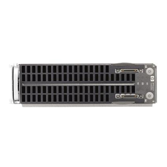
Workstation A HP c-Class Blade SUV Cable connector* Workstation A serial label pull tab Workstation A Power On/Standby button * The SUV connector and the HP c-Class Blade SUV Cable are for some workstation blade configuration and diagnostic procedures. Component identification 45... -
Page 46: Front Panel Leds
Front panel LEDs Item Description Status Workstation B system Green = On power LED Amber = Standby (auxiliary power available) Off = No power available to workstation Workstation B UID LED Blue = Identified Blue flashing = Active remote management Off = No active remote management Workstation B health LED Green = Normal... -
Page 47: Access Components
Item Description Status Workstation A system Green = On power LED Amber = Standby (auxiliary power available) Off = No power available to workstation * Actual NIC numbers depend on several factors, including the operating system installed on the workstation blade. Access components CAUTION: The jackscrews control the unseating and seating of critical system connectors. -
Page 48: System Board Components
System board components Workstation A system board components Item Description Internal USB connector Hard drive connector Processor socket 1 (populated) Processor socket 2 Workstation A serial number label Signal connector Enclosure connector System maintenance switch Mezzanine connector 1 Mezzanine connector 2 System battery DIMM slots Component identification 48... -
Page 49: Workstation B System Board Components
Workstation B system board components Item Description Hard drive connector Processor socket 2 Processor socket 1 (populated) System maintenance switch System battery Signal connector Workstation B serial number label DIMM slots Internal USB connector Component identification 49... -
Page 50: Workstation A Dimm Slots
Workstation A DIMM slots Workstation B DIMM slots Mezzanine connector definitions Item PCIe support Workstatino support Mezzanine connector 1 x8, Type I mezzanine card only Workstation A only Mezzanine connector 2 x8, Type 1 mezzanine card Workstation B only only A PCIe x8 mezzanine connector supports x16 cards at up to x8 speeds. -
Page 51: System Maintenance Switch
When the system maintenance switch position 6 is set to the On position, the system is prepared to erase all system configuration settings from both CMOS and NVRAM. CAUTION: Clearing CMOS and/or NVRAM deletes configuration information. Be sure to properly configure the workstation or data loss could occur. HP c-Class Blade SUV Cable Item Connector Description Workstation blade... -
Page 52: Specifications
Specifications Environmental specifications Specification Value Temperature range* Operating 10°C to 35°C (50°F to 95°F) Shipping -40°C to 60°C (-40°F to 140°F) Storage -20°C to 60°C (-4°F to 140°F) Maximum wet bulb temperature 30°C (86°F) Relative humidity (noncondensing)** Operating 10% to 90% Shipping 10% to 90% Storage... -
Page 53: Acronyms And Abbreviations
Acronyms and abbreviations Customer Self Repair Fibre Channel host bus adapter HP SIM HP Systems Insight Manager iLO 2 Integrated Lights-Out 2 Integrated Management Log PCIe peripheral component interconnect express POST Power-On Self Test RBSU ROM-Based Setup Utility SATA serial ATA... - Page 54 universal serial bus Acronyms and abbreviations 54...
-
Page 55: Index
Index hard drives 13 heatsink 15 HP c-Class Blade SUV Cable 40, 51 access components 47 HP Insight Diagnostics 43 accessing workstations 12 IML (Integrated Management Log) 43 battery 22, 38 Insight Diagnostics 43 battery pack, removing 24 Integrated Management Log (IML) 43... - Page 56 switches, configuring 51 symbols on equipment 10 system board 25, 31, 48 system board battery 38 system board components 48 system components 9, 45 temperature 52 temperature ranges (environmental) 52 tools 9, 43 troubleshooting 43 troubleshooting guidelines 43 USB connectors 51 USB devices 40, 41 USB support 44 utilities 43...
Need help?
Do you have a question about the ProLiant xw2x220c Blade Workstation and is the answer not in the manual?
Questions and answers