Table of Contents
Advertisement
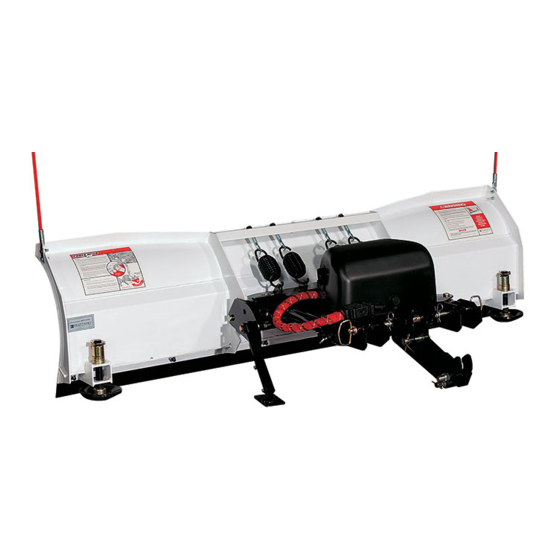
Models 680LT & 720LT
Installation Instructions & Owner's Manual
See your BLIZZARD sales outlet/Web site for
specifi c vehicle application recommendations
before installation. The Undercarriage
Selection Guide has specifi c vehicle and
snowplow requirements.
Read this document before installing the
snowplow.
Read this document before operating or
servicing snowplow.
This manual supersedes all editions with an earlier date.
CAUTION
CAUTION
CAUTION
March 1, 2009
Lit. No. B64118, Rev. 03
Advertisement
Table of Contents

Subscribe to Our Youtube Channel
Related Manuals for Blizzard 680LT


Summary of Contents for Blizzard 680LT
- Page 1 Lit. No. B64118, Rev. 03 Models 680LT & 720LT Installation Instructions & Owner's Manual CAUTION See your BLIZZARD sales outlet/Web site for specifi c vehicle application recommendations before installation. The Undercarriage Selection Guide has specifi c vehicle and snowplow requirements.
-
Page 2: Preface
PREFACE Congratulations on purchasing the fi nest straight When service is necessary, your local BLIZZARD blade snowplow available! BLIZZARD straight distributor knows your snowplow best. Contact your ® blades are clearing new trails for innovative design, BLIZZARD outlet for maintenance, service or any rugged durability, quality craftsmanship and superior other assistance you may require. -
Page 3: Table Of Contents
TABLE OF CONTENTS Preface ................ 2 POWER HITCH™ System Instructions ..... 30 Safety Information ............4 Testing Your Snowplow ..........31 Vehicle Application Information ........7 Headlamp Aiming ............33 Operation ..............8 Maintenance .............. 34 Unpacking & Inspection ..........9 Technical Specifi... -
Page 4: Safety Information
SAFETY SAFETY DEFINITIONS WARNING/CAUTION & INSTRUCTION LABELS WARNING Become familiar with and inform users about the Indicates a potentially hazardous situation, warning and instruction labels on the back of the that if not avoided, could result in death or blade. serious personal injury. -
Page 5: Safety Precautions
Plowing speed should not exceed 10 mph. components. Failure to do this could result in serious personal injury. CAUTION See your BLIZZARD outlet for application ® WARNING recommendations. You can die or be seriously injured. Keep... -
Page 6: Personal Safety
SAFETY PERSONAL SAFETY VENTILATION WARNING • Remove ignition key and put the vehicle in park or in gear to prevent others from starting the vehicle Vehicle exhaust contains lethal fumes. during installation or service. Breathing these fumes, even in low concentrations, can cause death. -
Page 7: Vehicle Application Information
BLIZZARD Undercarriage Selection Guide is properly behind the rear axle. A ballast retainer kit is based on available vehicle capacity for snowplow available from your BLIZZARD outlet, PN 62849. equipment on a representative vehicle equipped with options commonly used for plowing and with NOTE: The ballast retainer kit is for snowplow 300 lb of front seat occupant weight. -
Page 8: Operation
OPERATION Your snowplow is the most advanced and versatile A. Lowered or Float Position straight blade on the market. The easy-to-use controls Pushing the joystick forward, toward the allow you to automatically adjust the snowplow blade "Lower/Float" designation on the label, or into an infi... -
Page 9: Unpacking & Inspection
UNPACKING & INSPECTION Your BLIZZARD ® straight blade has been packaged Once you have inspected all parts and removed all to withstand transit and weather related damage. packaging materials, your snowplow is ready to be Fully inspect all components upon receipt of your fully assembled. -
Page 10: Torque Specifi Cations
TORQUE SPECIFICATIONS TORQUE CHART CAUTION Read instructions before assembling. Fasteners should be fi nger tight until instructed to tighten according to the torque chart. Use standard methods and practices when attaching snowplow including proper personal protective safety equipment. Grade Identifi cation for J429–Grade 5 Bolt Grade Identifi... - Page 11 TORQUE SPECIFICATIONS 37° JIC Flare Torque Values ft-lb Turns Size Assembly Steps min–max 6–7 1. Make sure the tubing and threads are clean. 8–9 2. Lubricate the threads with 10W hydraulic fl uid. 11–12 3. Hand tighten the nut/sleeve to approximately 30 in-lb. 14–15 4.
-
Page 12: Moldboard & A-Frame Assembly
MOLDBOARD & A-FRAME ASSEMBLY 1. Position the pivot beam and A-frame near the connecting points at the rear of the blade between the two center support ribs. Insert one 3/4" x 3-7/16" clevis pin through each mounting hole and secure with 1/4" x 1-1/2" cotter pin. Spring Loaded Adjustable Pivot Beam... - Page 13 MOLDBOARD & A-FRAME ASSEMBLY 3. Hook each extension spring to the receiving holes 4. Install the blade guides at each end of the on the pivot beam and attach the opposite end of moldboard. Insert the cap screw through the holes the spring to its respective spade bolts.
- Page 14 MOLDBOARD & A-FRAME ASSEMBLY 5. Remove the dust cap from both of the hydraulic Remove the plastic dust caps from the hydraulic angle cylinder ports and attach one 7/16" male lift cylinder ports. Attach one 7/16" 90° adjustable ORB adapter to each port. Connect the straight elbow ORB adapter to the extend port (base end) end of one 1/4"...
- Page 15 MOLDBOARD & A-FRAME ASSEMBLY 9. Remove the draw latch mount pin, spacer and NOTE: The A-frame latch, located at the cotter pin from the draw latch assembly. By rear/center of the A-frame, should be raised removing this pin, the inner draw latch plates can up to insert the draw latch mount pin.
-
Page 16: Electrical & Hydraulic Systems
MANIFOLD ASSEMBLY & ELECTRICAL INSTALLATION – SNOWPLOW SIDE NOTE: The snowplow side electrical harness and NOTE: The fl ow control knob will need to be connect/disconnect switch must be installed removed to install the fi tting into Port #3. before the manifold is secured. NOTE: DO NOT let any foreign objects enter 1. - Page 17 MANIFOLD ASSEMBLY & ELECTRICAL INSTALLATION – SNOWPLOW SIDE 6. Remove the bottom bolt, lock washer and fl at 9. Connect the hydraulic hoses to their respective washer from the rear pump mount bracket. Route adapters on the manifold. Hose PN B60293 the black ground wire (from the harness) under the Port #3, Hose PN B60432 Port #4 and Hose pump on the driver's side of the A-frame.
-
Page 18: General System Schematics
GENERAL SYSTEM SCHEMATICS B60344 – ELECTRICAL SCHEMATIC B60344 – HYDRAULIC SCHEMATIC RIGHT ANGLE LEFT ANGLE LIFT CYL. RAISE LOWER 3000 PSI T1 P1 Lit. No. B64118, Rev. 03 March 1, 2009... -
Page 19: Hydraulic Guide
HYDRAULIC GUIDE Hydraulic Valve & Hose Port Guide Models 680 & 720 Clockwise – Decrease Snowplow Drop Speed Pressure Gauge Counterclockwise – Increase Snowplow Drop Speed Quick Connect If being used with auxiliary hydraulics, recommended for systems having a flow rated at 4–30 gallons per minute (gpm) and a maximum pressure rating of 3,000psi. - Page 20 12 (+) VDC FUSED BLUE BROWN/WHITE ORANGE LIGHT GREEN WHITE BLACK PINK/BLACK VEHICLE HARNESS PLUG (2005) FACE VIEW LOOKING AT FEMALE CONNECTOR FEMALE TERMINALS BLIZZARD HARNESS PLUG (PLO W) WIRE STRIPE COLOR COLOR COLOR FUNCTION (PINK) (BLACK) PIN NUMBER BLACK...
-
Page 21: Electrical Schematics - Snowplow Side
ELECTRICAL SCHEMATICS – SNOWPLOW SIDE Lit. No. B64118, Rev. 03 March 1, 2009... - Page 22 ELECTRICAL SCHEMATICS – SNOWPLOW SIDE Lit. No. B64118, Rev. 03 March 1, 2009...
-
Page 23: Electrical Installation - Vehicle Side
ELECTRICAL INSTALLATION – VEHICLE SIDE CAUTION NOTE: Do not fasten the harness to areas that come in contact with moving engine parts or Before drilling any holes, check the selected possess extreme heat. The harness could become area for wires, hoses or other obstructions. tangled and/or melt causing electrical failure and 1. - Page 24 ® light conversion kit is not packaged with your screws. Insert the toggle switch through the snowplow. Contact your local BLIZZARD dealer to bracket and secure it with the hardware provided. obtain the appropriate conversion harness kit for Plug both of the switch leads into the toggle your vehicle.
- Page 25 Place the light tower Joystick Control into the pockets and re-lock the pins. See your local BLIZZARD dealer for complete installation ® instructions for your vehicle undercarriage. 14. Install the snowplow headlamps. Align one...
-
Page 26: Electrical Schematics - Vehicle Side
ELECTRICAL SCHEMATICS – VEHICLE SIDE Lit. No. B64118, Rev. 03 March 1, 2009... - Page 27 ELECTRICAL SCHEMATICS – VEHICLE SIDE Lit. No. B64118, Rev. 03 March 1, 2009...
- Page 28 ELECTRICAL SCHEMATICS – VEHICLE SIDE Lit. No. B64118, Rev. 03 March 1, 2009...
- Page 29 ELECTRICAL SCHEMATICS – VEHICLE SIDE Lit. No. B64118, Rev. 03 March 1, 2009...
-
Page 30: Power Hitch™ System Instructions
POWER HITCH™ SYSTEM INSTRUCTIONS Prior to operating your straight blade snowplow, review NOTE: If at any time the Mounting and the Mounting and Dismounting Instructions label on Dismounting Instructions label, or any other label the back of the driver-side moldboard. attached to your snowplow becomes illegible, promptly replace them. -
Page 31: Testing Your Snowplow
TESTING YOUR SNOWPLOW 1. Fill the hydraulic pump reservoir with BLIZZARD ® 3. Align the POWER HITCH arm on the A-frame Snowplow Rapid Action Hydraulic Fluid until it below the pushbeam, with the receiver plates in is approximately 3/4" from the top of the tank. - Page 32 TESTING YOUR SNOWPLOW is slow or delayed, the hydraulic fl uid is fi lling (No LED Float Light or Indicator Light) the cylinder and replacing the air in the system. Test the remaining functions of the snowplow. To lower the snowplow to the ground, push the joystick ahead (or up) or push the D button on the touchpad.
-
Page 33: Headlamp Aiming
HEADLAMP AIMING Fully tighten headlamp fasteners once correct visual e. Check functioning of any automatic vehicle aim is achieved. leveling systems and specifi c manufacturer's instructions pertaining to vehicle preparation 1. Place vehicle on a level surface 25 feet in front of for headlamp aiming. -
Page 34: Maintenance
Lubricate all pins and bushings, and A-frame latch with NLGI Grade 2 multi-purpose lithium complex grease with molybdenum (MPGM) to maintain consistent operation. Clean and paint all scratches or exposed metal with BLIZZARD touch-up paint. ®... -
Page 35: Technical Specifi Cations
Joystick or Touchpad * Weight does not include undercarriage. ** Amperage Draw specifi cations are based on snowplow lift operation, at a shop temperature of 65°F, using BLIZZARD ® Rapid Action Hydraulic Fluid. Amperage will vary with temperature, fl uid viscosity and meter accuracy. Deadheading a snowplow function will result in signifi cantly increased amperage. -
Page 36: Troubleshooting
Short in the control or wire Disconnect the control in the cab. If the pump turns a BLIZZARD outlet can diagnose ® harness. OFF, there is a short in the electrical system. - Page 37 TROUBLESHOOTING Problem Cause Solution The angle pressure relief valve is Check the pressure relief by testing the valve in-line set too low. NOTE: Increasing the with the cylinder. Attach a tee fi tting to the angle Snowplow will not stay angled pressure relief valve will cause cylinder hydraulic adapter and connect the hose when plowing.
-
Page 38: Parts Lists
MOLDBOARD PARTS – ALL MODELS Lit. No. B64118, Rev. 03 March 1, 2009... - Page 39 MOLDBOARD PARTS – ALL MODELS Item Part 680LT 720LT Description B81061 – Moldboard B81067 – Moldboard B81062 – Cutting Edge B81073 – Cutting Edge B61196 1/2-13 x 1-1/2 Carriage Bolt G8 B61365 1/2-13 Flanged Hex Locknut B61098 Plow Shoe Assy Standard (7-3/4 Shaft) (Incl. Items 5–7)
-
Page 40: A-Frame & Pivot Beam Parts - All Models
A-FRAME & PIVOT BEAM PARTS – ALL MODELS 33 32 Item Part Qty Description B83017 Pivot Beam 90601 1/4 x 1-1/2 Cotter Pin B41039 Kickstand Assembly (Incl. Items 3–10) B41047 Kickstand Foot B41038 Kickstand Leg 90665 1/2-13 x 1-1/4 Hex Cap Screw G8 90572 1/2 Hardened Flat Washer 90593... - Page 41 A-FRAME & PIVOT BEAM PARTS – ALL MODELS Item Part Qty Description B60426 1/4 x 25 45° Hydraulic Hose Plow Angle Left and Right Cylinder B60004 7/16-20 Hydraulic Adapter Male ORB B60254 Hydraulic Cylinder, Plow Raise/Lower B82061 5/8 x 5-3/4 Clevis Pin B60293 1/4 x 10 Hydraulic Hose Raise/Lower, Extend (Base End) B60008...
-
Page 42: Power Unit Parts - All Models
POWER UNIT PARTS – ALL MODELS Lit. No. B64118, Rev. 03 March 1, 2009... - Page 43 POWER UNIT PARTS – ALL MODELS Item Part Qty Description B60378 Pump/Manifold Kit (Incl. Items 1A, 9A, 17–19, 56805 [4], B60427, B61016 [2], B61214 [2], B61222 [2] & B62039) B60386 Power Unit-Pump Motor Tank Assy (Incl. Items 1–8, B61631, B61558, B60450, B61632 &...
-
Page 44: Lights & Control Parts - All Models
LIGHTS & CONTROL PARTS – ALL MODELS Item Part Qty Description B62039 Harness Assembly, Plow (Incl. Items 1–2, B62046, B62093, B61439 & B62167) B62057 Harness, Snowplow B62001 Weather Cap, Rubber, Snowplow Side B62046 Connector, Electric, Female, Plastic B62093 Terminal, Female (18-16 AWG) B61439 Cable Tie, Black,15"... - Page 45 LIGHTS & CONTROL PARTS – ALL MODELS Item Part Qty Description B80051 Power Contactor (Solenoid), 12V Continuous B62056 24" Ground Wire, Power Contactor B62072 3/8 End Ring Terminal Copper, 4 ga B62008 Fuse Clip, Mini B62009 Fuse Clip, Auto Blade B62016 Connector, Splice Lock (18-14 AWG) B61031...
-
Page 46: Accessories & Kits - All Models
(13.5" x 9" x 3.3") allows for easy storage behind zinc-free hydraulic fl uid maintains its viscosity to or under your seat. temperatures as low as –25°F. BLIZZARD fl uid is available by the quart, gallon, case or 55-gallon drum. - Page 47 B63078 12" Adjustable Pedestal Mount B63070 BLIZZARD Rapid Action Hydraulic Fluid (Quart) B63071 BLIZZARD Rapid Action Hydraulic Fluid (Case – 12 quarts) B63072 BLIZZARD Rapid Action Hydraulic Fluid (Gallon) B63069 BLIZZARD Rapid Action Hydraulic Fluid (Case – 4 gallons) B63091 BLIZZARD Rapid Action Hydraulic Fluid (Drum –...
- Page 48 Blizzard outlets or snowplow owner is granted. Blizzard reserves the right under its product improvement policy to change construction or design details and furnish equipment when so altered without reference to illustrations or specifi cations used. Blizzard or the vehicle manufacturer may require or recommend optional equipment for snow removal.
Need help?
Do you have a question about the 680LT and is the answer not in the manual?
Questions and answers