Table of Contents
Advertisement
Quick Links
INSTALLATION AND OPERATION INSTRUCTIONS
WM-BI-2428-VLR-BG
SAFETY INFORMATION
WARNING
For your safety, always comply with all
warnings and safety instructions
contained in this manual to prevent
personal injury or property damage.
Do not store or use gasoline or other flammable vapors
and liquids in the vicinity of this appliance.
INSTALLER: LEAVE OWNER'S MANUAL WITH THE APPLIANCE.
CONSUMER: RETAIN OWNER'S MANUAL FOR FUTURE REFERENCE.
Dated - 06.27.21 AC
Advertisement
Table of Contents

Subscribe to Our Youtube Channel
Related Manuals for Amantii WM-BI-2428-VLR-BG


Summary of Contents for Amantii WM-BI-2428-VLR-BG
- Page 1 INSTALLATION AND OPERATION INSTRUCTIONS WM-BI-2428-VLR-BG SAFETY INFORMATION WARNING For your safety, always comply with all warnings and safety instructions contained in this manual to prevent personal injury or property damage. Do not store or use gasoline or other flammable vapors and liquids in the vicinity of this appliance.
-
Page 2: Table Of Contents
GROUNDING APPLIANCE ..........................4 LOCATING THE FIREPLACE ........................4 CLEARANCES WHEN BUILT-IN........................5 INSTALLATION-WALL MOUNT ........................7 WM-BI-2428-VLR-BG............................. 8 INSTALLATION OVERVIEW – MASONRY FIREPLACES ................9 INSTALLATION OVERVIEW –ZERO-CLEARANCE (METAL) FIREPLACES ..........10 HARD- WIRE INSTALLATION........................11 MEDIA OPTIONS ............................12 FIRE GLASS MEDIA INSTALLATION...................... -
Page 3: Important Instructions
IMPORTANT INSTRUCTIONS Read all instructions before installing or using this heater. 2. Keep combustible materials, such as furniture, pillows, bedding, papers, clothes and curtains at least 3 feet from the front of the heater; keep them away from sides and rear as well. -
Page 4: Unpacking And Testing Appliance
UNPACKING AND TESTING APPLIANCE Carefully remove the appliance from the box. Remove the packing screws from both sides of the fireplace. Prior to installing the appliance, test to make sure the appliance operates properly by plugging the power supply cord into a conveniently located 120 Volt grounded outlet. Test all aspects of its operation (manual switches, remote and heater) to make sure all components operate correctly. -
Page 5: Clearances When Built-In
2. Consider a location where the fireplace screen will not be exposed to direct sunlight from windows or doors. A 15 ampere, 120 Volt, 60 Hz branch circuit with proper ground must be available at the location. Preferably a dedicated branch circuit should be provided to avoid circuit breakers to trip of fuses to blow. - Page 6 Please see the following figures. It shows the dimension of fireplace when it install in different way. a. Fireplace with flat glass insert to the wall. b. Fireplace with curve glass insert to the wall. 18" 19 1 2 " c.
-
Page 7: Installation-Wall Mount
INSTALLATION-WALL MOUNT 1. Select a location that is not prone to moisture and is located at least 0.91 m or 3 feet away from combustible materials such as curtains or drapes, furniture, bedding, paper, etc. 2. Refer to Fig. 1 right select a suitable position in which to mount the heater Fig. -
Page 8: Wm-Bi-2428-Vlr-Bg
WM-BI-2428-VLR-BG Description Built-in or Wall mount Appliance This appliance has been tested in Voltage 120V AC 60Hz accordance with the UL Standard 2021 1465W Max Watts for fixed and location dedicated NO HEATER electric room appliances in the United MOTOR HEATER States and Canada. -
Page 9: Installation Overview - Masonry Fireplaces
INSTALLATION OVERVIEW – MASONRY FIREPLACES Cover plate is required if chimney does not have suitable rain cap. 2” (50mm) Minimum HINT: Close and seal the damper to prevent air infiltration. Attach the "This fireplace has been altered..." plate to the fireplace (use two screws or other suitable method). -
Page 10: Installation Overview -Zero-Clearance (Metal) Fireplaces
INSTALLATION OVERVIEW –ZERO-CLEARANCE (METAL) FIREPLACES Cover plate is required if chimney does not have suitable rain cap. The log shelf, screen, and doors (if present) must be removed. 2” (5.08cm Minimum HINT: Close and seal the damper to prevent air infiltration. HINT: Attach the "This fireplace has been Paint the interior of the... -
Page 11: Hard- Wire Installation
HARD- WIRE INSTALLATION Turn off the appliance completely and let cool before servicing. Only a qualified service person should service and repair this electric appliance. If it is necessary to hard wire this appliance, a qualified electrician must remove the cord connection, and wire the appliance directly to the household wiring. -
Page 12: Media Options
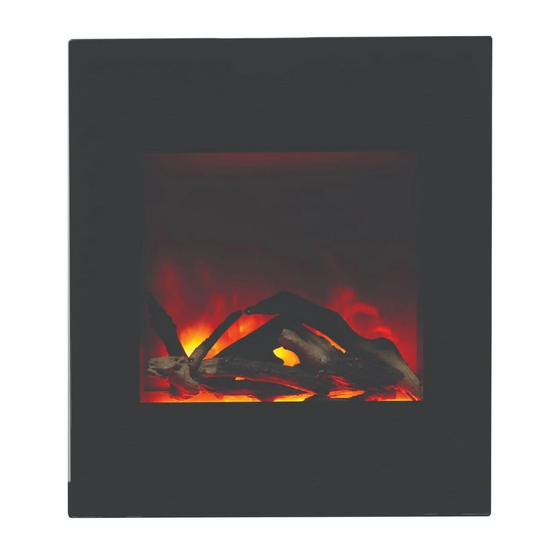
MEDIA OPTIONS This fireplace shipped with oak log set and sable. 3. Use the new tray glass holder bracket for the curve glass. oak log set sable FIRE GLASS MEDIA INSTALLATION Unplug the unit from wall and make sure 4. Change the new tray glass and screw the controls are switched off. -
Page 13: Operation
OPERATION The fireplace can be operated either by the switches located on the left front of the fireplace unit or by supplied remote control. MANUAL OPERATION 1. The main power ON/OFF switch in position O, the fireplace is OFF. 2. When main power ON/OFF switch is at position I, the fireplace is ready to use. 3. -
Page 14: Remote Control Operation
REMOTE CONTROL OPERATION DISPLAY ON/OFF YELLOW DISPLAY ORANGE MOOD LIGHT ON/OFF ADJUST FLASH HEATER ON/OFF HIGH TEMP. For remote to function make sure the heater is plugged in and main power switch located on the bottom left hand side is at position I. When operating the remote make sure you point the remote to the centre of the fireplace and make sure each time you press the button the buzzer inside the unit will beep once. -
Page 15: Installing Wall Thermostat
INSTALLING WALL THERMOSTAT WALL THERMOSTAT WIRING DIAGRAMS NOTE: THE WALL THERMOSTAT WILL WOKING WHEN THE HEATER ON TEMP. SETTING.PLEASE REEFER TO THE MANUAL CONTROL AND THE REMOTE CONTROL. Wire the wall thermostat prior to installing the fireplace. WALL THERMOSTAT WIRING(24 AWG) Install Wall Thermostat per instructions provided with kit and per the following information: 1. -
Page 16: Replacement Parts
REPLACEMENT PARTS PART NUMBER DESCRIPTION QTY. TOP PANEL BACK TOP PANEL 601097B CIRCUIT BOARD 602067D BLOWER AND HEATER ASSEMBLY 3056001 FIREPLACE BOX 10125025 TOP LED STRIP 10104010 TOP LED BRACKET 601036 CONTROL PANEL 301506 REMOTE RECEIVER 10103007 POWER CORD 10104002 SWITCH 3056505 FLICKER ASSEMBLY... -
Page 17: Exploded View
EXPLODED VIEW... -
Page 18: Trouble Shooting
TROUBLE SHOOTING PROBLEM POSSIBLE CAUSE SOLUTION Dim or no flame Flame LED’s are burnt out Inspect the LED’s and replace them if necessary. Back black cloth is falling off Change a new flicker and back black and roll the flicker cloth. -
Page 19: Service History
SERVICE HISTORY This heater must be serviced annually depending on usage. Date Dealer Service technician Service Performed Special Concerns Name Name NOTES:...
Need help?
Do you have a question about the WM-BI-2428-VLR-BG and is the answer not in the manual?
Questions and answers