
Related Manuals for Autronica BSL-330


Summary of Contents for Autronica BSL-330
- Page 1 Interactive Fire Alarm System Installation & Commissioning Handbook, User Guide Modbus Interface Module BSL-330 AutroCom Protocol Version 1.1 Protecting environment, life and property... P-BSL330/IE...
- Page 2 This publication, or parts thereof, may not be reproduced in any form, by any method, for any purpose. Autronica Fire and Security AS and its subsidaries assume no reponsibility for any errors that may appear in the publication, or for damages arising from the information in it.
-
Page 3: Table Of Contents
Cable Connections................11 Entering Executive Mode ..............12 Setting Parameters / Configuration Program........13 4. Installation............... 14 Overview ....................14 Mounting the BSL-330 Module ............15 Connecting the RS-232 Serial Interface Cable........16 Overview - Cable Connections ............16 5. Commissioning ............... 17 Overview ....................17 Step-by-step Procedure ..............18 How to Use the AutroSafe Data and Registers .........19... - Page 4 5.4.5 Date & Time Register (Read/Write Holding Registers 2 & 3) 24 6. Appendix................25 Terms and Abbreviations..............25 7. Reader’s Comments ............27 Installation & Commissioning Handbook, User Guide, AutroSafe Interactive Fire Alarm System, P-BSL330/IE, Autronica Fire and Security AS Page 2...
-
Page 5: Introduction
This handbook is intended to provide all necessary information for the installation and commissioning of the Modbus Interface Module BSL-330, hereby called the BSL-330 module. The commissioning section gives guidelines on how to use the specific AutroSafe configuration data and mapping registers to perform the register mapping and configuration / programming of various external PLC equipment (Programmable Logic Controllers). -
Page 6: The Product
Introduction 1.4 The Product The BSL-330 module is an RS-232/422/485 interface module used to interface various PLC equipment (Programmable Logic Controllers) to the AutroSafe Interactive Fire Alarm System. Refer to detailed description and specification in section 2 in this handbook. -
Page 7: Overview
Fire Brig. Fault Serial Port System Fault Communication Alarms Disabled Alarms Fault Board EAU-321 â â 1.6 Typical Application The drawing below shows a typical application of the BSL-330 module. BSL-330 BSL-330 Slave Slave Master Master Slave Slave PORT 1 PORT 1... -
Page 8: Reference Documentation
Introduction 1.7 Reference Documentation In addition to this handbook, Autronica Fire and Security offers the following documentation: Handbook Item Number System Specification P-ASAFE/XE Installation Handbook, Fire Alarm Control Panel (BS-310/320) / Controller (BC-320) P-ASAFE-FA/DE Installation Handbook, Operator Panel (BS-330) P-ASAFE-OP/DE... -
Page 9: The Modbus Interface Module
Modbus PLC • users to send basic commands to the AutroSafe from a Modbus The Modbus PLC acts as “master” to the BSL-330, and the AutroSafe as “slave” to the BSL-330. The AutroSafe appears to the Modbus PLC as a Modbus slave. -
Page 10: Specifications
29mm (W) x 112mm (H) x 103mm (L) approximately in rail-mounted position, including screw terminals. 2.3 Dimensions The drawing below shows the dimensions of the BSL-330 module. Installation & Commissioning Handbook, User Guide, AutroSafe Interactive Fire Alarm System, P-BSL330/IE, Autronica Fire and Security AS... -
Page 11: Indicators & Buttons On The Front Panel
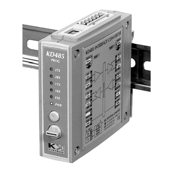
The Modbus Interface Module 2.4 Indicators & Buttons on the Front Panel The BSL-330 module has the following indicators and buttons: Red LED - Send (TX) Port 2 (to external PLC equipment). KD485 Blinking light (2 seconds intervals) indicates that signals are being sent. -
Page 12: Preparing For Commissioning
The necessary preparations, include the following: • The dip-switches must be verified (factory set) • The BSL-330 module must be connected to a 24V DC power source • The BSL-330 module must be connected to a computer's serial port •... -
Page 13: Cable Connections
• Consult the cable drawing below. • Connect the cable from the 24V DC power source to the connector (Port 1) on the BSL-330 module. • Connect the cable from the computer''s serial port to the connector (Port 1) on the BSL-330 module. -
Page 14: Entering Executive Mode
Preparing for Commissioning 3.4 Entering Executive Mode The BSL-330 module must be electronically configured before it can be used. Configuration must be done via Port 1, which has to be set to Executive Mode. • To enter Executive Mode, press and hold down the green Executive Mode button on the front panel approximately 5 seconds until the EXE indicator starts blinking, then release it. -
Page 15: Setting Parameters / Configuration Program
KD485 Configuration Program, which is delivered with the BSL-330 module. • Make sure that the BSL-330 module is in Executive Mode. The EXE indicator should be blinking rapidly. If not, communication is not established, and you must repeat the procedure described in the previous section (Entering Executive Mode). -
Page 16: Installation
4. Installation 4.1 Overview The drawing below gives an overview of the screw terminals. (Bottom view) (Top view) (Front panel view) Installation & Commissioning Handbook, User Guide, AutroSafe Interactive Fire Alarm System, P-BSL330/IE, Autronica Fire and Security AS Page 14... -
Page 17: Mounting The Bsl-330 Module
DIN rail clip NOTE: If the BSL-330 module is to be removed from the rail, gently lift the front end upwards. If necessary, use a flat screwdriver to open up the DIN rail clip. Note that very little force is required. -
Page 18: Connecting The Rs-232 Serial Interface Cable
If the BSL-330 module is placed outside the AutroSafe BS-320 Fire Alarm Control Panel, the maximum distance from the EAU-321 board to the BSL-330 module is 10 meters. • Continue following the step-by-step procedure described in the next section Commissioning. -
Page 19: Commissioning
AutroCom, and keeps the accumulated results in a list of registers internally. The PLC polls the BSL-330 module for reading its registers. It expects a response within a defined time period. Communications can be over various serial mediums. The one used here is the MODBUS RTU protocol over an RS485 link. -
Page 20: Step-By-Step Procedure
Install and connect the BSL-330 module as described in the previous section. Power up the BSL-330 module - connect the cable from the 24V DC power source to the connector (Port 1) on the BSL-330 module (refer to the cable connections overview on the previous page).
Need help?
Do you have a question about the BSL-330 and is the answer not in the manual?
Questions and answers