Table of Contents
Advertisement
Quick Links
Advertisement
Table of Contents

Related Manuals for Foxtech Naga Pro MX16


Summary of Contents for Foxtech Naga Pro MX16
- Page 1 NAGA PRO User Manual NAGA PRO User Manual (MX16 Version)
-
Page 2: Table Of Contents
NAGA PRO User Manual Content 一. Assembly....................... 1 1. Unfold the Arm....................1 2. Turn on MX16 GCS..................3 3. Install Battery....................5 4. Install Propeller....................10 二. MX16 Introduction..................14 1. MX16 GCS Diagram...................14 2. Air Unit Interface..................15 3. Status Prompt Bar..................16 4. MX16 Assistant................... 17 5. - Page 3 NAGA PRO User Manual 3. Loading Firmware to The Cube..............30 4. Basic Hardware Calibration and Parameter Setting........31 4.1 Frame Type Configuration..............31 4.2 Accelerometer and Compass Calibration..........32 4.2.1 Accelerometer Calibration............... 32 4.2.2 Level Calibration................36 4.2.3 Compass Calibration................ 37 4.2.4 Remote Controller Calibration............39 4.2.5 ESC Calibration................40 4.2.6 Select Flight Modes................41...
- Page 4 NAGA PRO User Manual 2. Camera and Aircraft Connection..............55 3. Photo Taking Test..................56 八. FAQ......................58 九. Troubleshooting Guide................63 十. How to Use QGC..................64...
-
Page 5: 一.Assembly
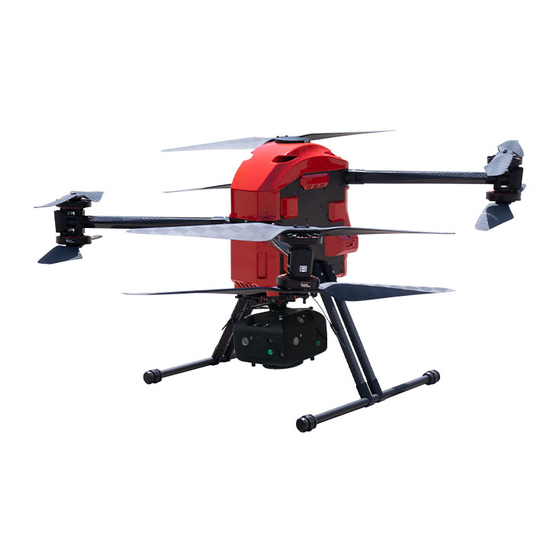
NAGA PRO User Manual 一.Assembly NAGA PRO(MX16 version) accessories are shown in the following figure, including 1x NAGA Pro UAV, 4x Propeller, 1x landing gear, 1x MX16 GCS, 1x charger, 2x battery. 1. Unfold the Arm First unfold the lower arm of the fuselage around the rotation axis, and then unfold the upper arm, snap the arm buckle into the green locking piece, and turn the green locking piece clockwise to lock the arm. - Page 6 NAGA PRO User Manual...
-
Page 7: Turn On Mx16 Gcs
NAGA PRO User Manual 2. Turn on MX16 GCS Long press the power button to turn on MX16, and then click the QGC icon to enter the ground station software. - Page 8 NAGA PRO User Manual Enter the ground station software and wait for the aircraft to automatically connect.
-
Page 9: Install Battery
NAGA PRO User Manual 3. Install Battery... - Page 10 NAGA PRO User Manual...
- Page 11 NAGA PRO User Manual...
- Page 12 NAGA PRO User Manual...
- Page 13 NAGA PRO User Manual...
-
Page 14: Install Propeller
NAGA PRO User Manual 4. Install Propeller The motors are divided into upper and lower parts. The upper motors are defined as No. 1, No. 2, No. 3, and No. 4. The lower motors are defined as No.5, No. 6, No. 7, No. 8. The stickers for motor are attached to the end of arms, and propellers also have stickers corresponding to the motors. - Page 15 NAGA PRO User Manual...
- Page 16 NAGA PRO User Manual...
- Page 17 NAGA PRO User Manual...
-
Page 18: 二.Mx16 Introduction
NAGA PRO User Manual 二.MX16 Introduction 1. MX16 GCS Diagram Note Note 2.4G 3dB antenna Set Button 3-position switch SW2 Right joystick X2. Y2 3-position switch SW1 3-position SW4 Left joystick X1. Y1 3-position SW3 Small joystick X3. Y3 Knob AUX2 Power button Knob AUX1 6-segment switch... -
Page 19: Air Unit Interface
NAGA PRO User Manual Note Note UART 0 Power and SBUS input UART 1 Type-C port MIPI camera port TF card port HDMI input Frequency pairing button 2. Air Unit Interface... -
Page 20: Status Prompt Bar
NAGA PRO User Manual 3. Status Prompt Bar 1. Access to internet successfully through Ethernet port or USB 2. Remote controller and receiver signal strength(the receiver is not connected in the picture) 3. Power... -
Page 21: Mx16 Assistant
NAGA PRO User Manual 4. Time 5. Return 6. Back to the main surface 7. Background task management/split screen button 4. MX16 Assistant 1. Switch the joystick control method of the remote controller. 2. Check the channel value of the remote control. 3. -
Page 22: Mode Changing
NAGA PRO User Manual ①Wait for 3s-5s after the receiver is powered on, and then long press the SET button until the white light flashes. ②Enter MX16 assistant and click frequency matching.(it will display ‘connected’ after the frequency successfully matched) Mode Changing The operation mode can be set according to customer requirements. - Page 23 NAGA PRO User Manual...
-
Page 24: Channel Reverse
NAGA PRO User Manual 7. Channel Reverse If the channel is found to be reversed during use, you can change it according to the following steps:... - Page 25 NAGA PRO User Manual...
- Page 26 NAGA PRO User Manual...
-
Page 27: Image Connection And Setting
NAGA PRO User Manual 8. Image Connection and Setting... -
Page 28: Joystick Calibration
NAGA PRO User Manual ①The factory default mode is HDMI/MIPI, used to display image transmitted via receiver MIPI/HDMI ②UART VIDEO Mode to display single-axis gimbal camera and MINI camera images(only applicable to 680 device) ③Custom mode, display the image transmitted through the air unit Ethernet port. 9. -
Page 29: Connect Fc And Datalink In Qgc
NAGA PRO User Manual ①Click System Setting icon in QGC ②Click ‘General’ ③Change the video source to RTSP Video Stream ④Input the video RTSP address in RTSP URL To display MIPI and HDMI image, input rtsp://192.168.0.10:8554/H264Vide in RTSP URL 11. - Page 30 NAGA PRO User Manual...
-
Page 31: Share Network, Video And Data Information
NAGA PRO User Manual 12. Share Network, Video and Data information Share the Internet When the remote controller is connected to the Internet via the USB wireless card, the hot spot of the remote controller can be turned on for network sharing. ... - Page 32 NAGA PRO User Manual Share the Video link (1)Open the hot spot of the remote controller. (2)Connect the computer to the remote controller’s hot spot. (3)Open the computer’s settings, click on the adapter, select Ethernet, select the IPV4 protocol, select a custom IP address, enter as shown in the figure, then click on “confirm”. (4)Download VCL software to display the video.
-
Page 33: 三.Mission Planner Operation Guide
NAGA PRO User Manual 三.Mission Planner Operation Guide 1. Download Mission Planner Before installing firmware for The Cube, please download stable version of Mission Planner from ArduPilot website. Mission Planner currently supports Windows, just download the corresponding version according to your need. Using Windows 10 as example, download the .msi installation file and run it as administrator. -
Page 34: Connect Mission Planner To The Cube
NAGA PRO User Manual dialog box pop up. Software download URL::http://firmware.ardupilot.org/Tools/MissionPlanner/ 2. Connect Mission Planner to The Cube Connecting The Cube usually has two connection methods: wireless data transmission and USB. Mission Planner also supports Bluetooth and IP address connections. No matter what kind of connection you use, your data transmission driver or serial port driver must be installed correctly to ensure the normal operation of the data link, then the Cube can be connected to the ground station. -
Page 35: Basic Hardware Calibration And Parameter Setting
NAGA PRO User Manual Before installing the firmware, select the corresponding device and baud rate (the same configuration as when connecting the device). Don’t hit Connect just yet. On the Mission Planner’s "Initial Setup > Install Firmware"" screen select the appropriate icon that matches your frame (i.e. -
Page 36: Accelerometer And Compass Calibration
NAGA PRO User Manual 4.2 Accelerometer and Compass Calibration Go to "Initial Setup > Mandatory Hardware > Accel Calibration". Click Calibrate Accel to start the calibration. Pointing the nose of aircraft to LEVEL, LEFT, RIGHT, NOSEDOWN, NOSEUP, and BACK according to the message below. "Calibration successful" will be shown after calibration completed successfully. - Page 37 NAGA PRO User Manual Place the aircraft nose to front and left-hand-side to the ground then press any button to continue. Place the aircraft nose to front and right-hand-side to the ground then press any button to continue.
- Page 38 NAGA PRO User Manual Place the aircraft nose to the ground then press any button to continue.
- Page 39 NAGA PRO User Manual Place the aircraft nose to upward then press any button to continue. Place the aircraft upside-down then press any button to continue.
-
Page 40: Level Calibration
NAGA PRO User Manual "Calibration successful" will be shown after calibration completed successfully. 4.2.2 Level Calibration Place the aircraft horizontally and click "Calibrate Level". The text in button will become "Completed" after calibration successful. -
Page 41: Compass Calibration
NAGA PRO User Manual 4.2.3 Compass Calibration Go to "Initial Setup > Mandatory Hardware >HWID", check the ID number of the CAN port compass, and then select the compass. Select to enable the Use compass ID number according to the ID number of the CAN port compass, and adjust the use priority of the CAN port compass to the best. - Page 42 NAGA PRO User Manual If calibration is successful, the window below will show "success". "success" will also be shown on compass. Upon successful completion, a “Please reboot the autopilot” window will appear. Click OK, unplug and replug the USB.
-
Page 43: Remote Controller Calibration
NAGA PRO User Manual If, after multiple attempts, you are unable to calibrate the compass, Press the “Cancel” button and change the “Fitness” drop-down to a more relaxed setting and try again. Normally, select Default. 4.2.4 Remote Controller Calibration Connect the RC receiver to The Cube via RCIN and turn on your RC transmitter. Then click the remote control calibration button in the lower right corner of the window, and toggle the remote control switch to move the red prompt bar of each channel to the upper and lower limit positions. -
Page 44: Esc Calibration
NAGA PRO User Manual 4.2.5 ESC Calibration Safety Checking: Before calibrating the ESC, please make sure that there is no propeller mounted on the aircraft. Connect NAGA Pro to MP ground control station via data link. Select the "Configuration > Full Parameter List >... -
Page 45: Select Flight Modes
NAGA PRO User Manual 4.2.6 Select Flight Modes Set the 5 channel or the other channel on the remote controller (which can be set by all parameters FLTMODE-CH) to the appropriate position. Missioon Planner will display the current position in green, select a mode for each switch and click the save mode button. The remote controller can set up to 6 flight modes, and you can set up 6 single-channel mixing according to your own remote controller instructions. - Page 46 NAGA PRO User Manual Four commonly used flight modes: ALT HOLD After the first test flight, you can try the altitude hold mode. This mode does not require GPS support. The autopilot will maintain the current altitude based on the data from the air pressure sensor.
-
Page 47: 四.Mission Planner Rtk Setting
NAGA PRO User Manual In this mode, the aircraft will automatically perform tasks set by the Mission Planner on the ground station, such as taking off and flying to multiple waypoints in sequence, rotating, and taking pictures. RTL GPS positioning is required for the return home mode. The GPS positioning point before ARM is the current "home"... - Page 48 NAGA PRO User Manual Open the Mission Planner ground station software on your computer and enter the initial setup→Optional Hardware→RTK/GPS Inject, you will see the following page: Select the correct base station port in the upper left corner and click connect. In the SurveyIn Acc column, enter the absolute geographic accuracy you expect your HERE+ base station to achieve.In the Time field, enter the shortest search time you expect.
- Page 49 NAGA PRO User Manual During the satellite search process, the box on the right side of the Mission Planner page will display the current position of the satellite searching: Position is invalid: the base station has not yet achieved effective positioning; ...
- Page 50 NAGA PRO User Manual In the figure, the indicator light showing the status of the base station is shown in green, and the two satellite systems, GPS and Glonass, are shown in green (if you want to change the satellite system, please refer to the instructions in the following chapters). The box on the right is displayed as Position is valid.
-
Page 51: How To Use Base Station
NAGA PRO User Manual 2. How to Use Base Station Open the Mission Planner ground station software on your computer, enter the initial setup→Optional Hardware→RTK/GPS Inject page, select the correct base station port in the upper left corner, and then click connect. You will see the following page:... -
Page 52: 五.First Take-Off
NAGA PRO User Manual Enter the latitude and longitude of the known fixed station and the measured height of the RTK antenna relative to the ground at the position in the figure below, and then click the use button. Note: The RTK antenna placement position should coincide with the fixed point position as much as possible. -
Page 53: Meaning Of Led Indicator Light
NAGA PRO User Manual If the blue light or green light flashes, the buzzer will emit a low-pitched sound after unlocking, and the motor will start idling and can take off. 2. Meaning of LED Indicator Light: Flashing red and blue:Initializing sensors and auto-check the autopilot. Please lay down the flight controller. - Page 54 NAGA PRO User Manual in detail whether the hardware installation is correct (especially whether the arm is locked in place, the battery compartment cover is tightly locked, whether the landing gear is locked, whether the external load is installed firmly, the direction of the propeller, etc.). After confirming that there is no problem, perform the following steps : ...
- Page 55 NAGA PRO User Manual Unlock through the ground control station. Under the premise that the autopilot has a link to the ground, there is an action tab at the bottom of the HUD window of the ground control station. Click the unlock button inside to unlock. ...
-
Page 56: Disarm The Drone
NAGA PRO User Manual Take off: raise the throttle to take off, and control the direction according to the attitude. (if the novice is not familiar with the control, you can practice the flight simulator first, so as to avoid the explosion of the aircraft and the loss of personnel and property) If there is no operation within 15 seconds after unlocking, it will be automatically locked. - Page 57 NAGA PRO User Manual The main explanation here is the mission planning function of the MP ground control station, but the waypoint planning concepts of other ground control stations are actually very similar. Create a multi-waypoint area in the MP mission planning interface ...
- Page 58 NAGA PRO User Manual The mission planner will display the configuration interface. This interface defines the camera parameters automatically calculates shooting distance DO_SET_CAM_TRIGG_DIST command parameters, you can also set the parameters according to the actual situation. If you accept these parameters, please click accept. The mission planner will generate a series of waypoints covering the designated area, including the take-off point and the landing point.
-
Page 59: 七.How To Use Oblique Camera
NAGA PRO User Manual command, and finally call DO_SET_CAM_TRIGG_DIST again to set the parameter back to 0 and stop taking pictures; Note that the parameters of two call are different. 七.How to Use Oblique Camera 1. Camera Function Buttons 2. Camera and Aircraft Connection... -
Page 60: Photo Taking Test
NAGA PRO User Manual 3. Photo Taking Test... - Page 61 NAGA PRO User Manual...
-
Page 62: 八.Faq
NAGA PRO User Manual 八.FAQ 1. Bad AHRS The cause of the problem: the acceleration and level are not calibrated, or the calibration is wrong. Added GPS, but the GPS is not fixed, or the GPS arrow is not consistent with the flight controller. - Page 63 NAGA PRO User Manual Solution: Correctly calibrate the acceleration, power off the flight controller after calibration, reconnect, and calibrate the level,this step is very important. Assemble the GPS correctly, make sure the GPS is fixed, and the arrow of the GPS and the arrow of the flight controller should be the same.
- Page 64 NAGA PRO User Manual configuration debugging\standard parameters, don't check the board voltage, and others can be checked or unchecked. Remove the check,then remember to click the "Write Parameters" button above, then power off the flight controller and reconnect it). 5. Compasses inconsistent solution The cause of the problem: Compasses inconsistent means that the compass is out of sync.
- Page 65 NAGA PRO User Manual 10. Compass offsets too high The cause of the problem: The offset value of the main compass (i.e. sqrt(x^2+y^2+z^2)) is greater than 500, and this will be prompted. Generally, there are magnetic objects (motors, screws,battery) near the flight controller or GPS, or the environment has strong magnetic interference.
- Page 66 NAGA PRO User Manual Cause of the problem: This may be a hardware problem, or it may be that flight controller is started immediately after flashing the firmware. Solution: Re-power on the flight controller and reconnect it. 17. Gyros not healthy The cause of the problem: the data of the gyroscope fluctuates badly, the value is out of range, and there is no data.
-
Page 67: 九.Troubleshooting Guide
NAGA PRO User Manual the ground control station sees it is upward), and the other channels are the same as the ground control station. If not, it means the channel direction is wrong, reverse setting and then re-calibrate. - When the indoor flight is unlocked, the correct flight mode is not selected: there is no GPS signal indoors, and the fixed-point or loiter flight mode needs to be positioned in flight mode, that is, the flight controller can only be unlocked after finding the GPS signal positioning. -
Page 68: 十.How To Use Qgc
NAGA PRO User Manual points: Check if the frame setting X or + is correct Check if the ESC serial number is correct Check if the motor rotation is correct Whether the propeller direction is correct and whether the wind is blowing downwards ...
Need help?
Do you have a question about the Naga Pro MX16 and is the answer not in the manual?
Questions and answers