Foxtech VDC-7 User Manual

Foxtech VDC-7 User Manual

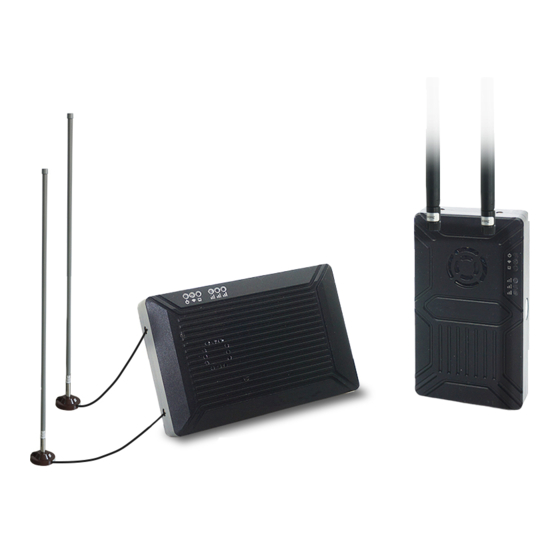
Long range video/data/rc transmission system

Advertisement

Quick Links

VDC-7/VDC-15
Long Range Video/Data/RC Transmission System
User Manual
2020.06
V2.0

Advertisement

Table of Contents
loading
Need help?

Need help?

Do you have a question about the VDC-7 and is the answer not in the manual?

Questions and answers

Subscribe to Our Youtube Channel

Summary of Contents for Foxtech VDC-7

  • Page 1 VDC-7/VDC-15 Long Range Video/Data/RC Transmission System User Manual 2020.06 V2.0...
  • Page 2: Table Of Contents

    VDC-7/VDC-15 Long Range Video/Data/RC Transmission System User Manual Contents Note Packing List Important Notice Product Introduction Air Unit Interface Definition Ground Unit Interface Installation Ground Get Video Get data VDC-7/VDC-15 Instruction Quick Start VDC-7/VDC-15 with Mission Planner VDC-7/VDC-15 with VLC...
  • Page 3: Note

    · This copyright of this manual belongs to FOXTECH. No one may make copies without written consent. 2020 FOXTECH All Rights Reserved ©...
  • Page 4: Packing List

    VDC-7/VDC-15 Long Range Video/Data/RC Transmission System User Manual Packing List Air unit Ground unit Accessories 7Pin cable Antenna HDMI cable For Power and UART1 For air unit For the connection of the gimbal (HDMI camera) and the air unit Fiber-glass antenna x2...
  • Page 5: Important Notice

    VDC-7/VDC-15 Long Range Video/Data/RC Transmission System User Manual Important Notice Attention to installation 1.Before power on, make sure the antenna connection is reliably. Otherwise, it will cause damage to the device. 2.Make sure that the voltage is within the range of use.
  • Page 6: Product Introduction

    Users can use it for flight control data and gimbal control data transmission. Also the system can improve the RC control distance via the SBUS port. On the ground unit of VDC-7/VDC-15, there is a USB 3.0 port. User can add a USB storage device to save the FHD video.
  • Page 7: Air Unit Interface Definition

    VDC-7/VDC-15 Long Range Video/Data/RC Transmission System User Manual Air Unit Interface Definition 1 2 3 1.Power indicator This indicator is solid green when air unit is booting. When air unit has started, indicator light blinks once per second if there is no video source input to HDMI.
  • Page 8 VDC-7/VDC-15 Long Range Video/Data/RC Transmission System User Manual 5.DC/UART1 Number Character Description Input/Output +Vcc Power Input (9~28V) 3,4,7 TXD from air unit to external RXD from external to air unit 6.Ethernet Number Character Description Input/Output 7.UART2 Number Character Description Input/Output...
  • Page 9 VDC-7/VDC-15 Long Range Video/Data/RC Transmission System User Manual 10.Type A HDMI video input interface 11.Button Press 10 seconds, air unit will restore all parameters to factory setting 12.Mode switch WB is wide band using wide wireless frequency band. NB is narrow band using narrow band to multi-modules transmission.
  • Page 10: Ground Unit Interface

    VDC-7/VDC-15 Long Range Video/Data/RC Transmission System User Manual Ground Unit Interface 1 2 3 4 1.Power indicator This indicator is solid green when ground unit is power on 2.Link indicator LED Pattern Description solid green Wireless link is established light off Wireless link is lost 3.Status indicator...
  • Page 11 VDC-7/VDC-15 Long Range Video/Data/RC Transmission System User Manual 5 Ethernet port RJ45 Connecting to host computer. Support RTSP/TCP/UDP protocol. 6.USB port Type A Connect to USB disk for video recording 7.SBUS input port Number Character Description Input/Output +5V Output SBUS_IN 8.UART2...
  • Page 12: Installation

    VDC-7/VDC-15 Long Range Video/Data/RC Transmission System User Manual Installation 1.Installing the air unit on your drone Insert the MMCX-to-SMA cable into the ports on the side of the air unit. When you hear a click, it means good connection. Fixed the device and RF cable on your drone. Install the antenna. Pay attention to the connection of the antenna to tighten.
  • Page 13: Ground

    Connect the HDMI port with HDMI cable to a monitor. The FHD video signal will be displayed on the monitor directly. 2.Connect to the Ground Station Ground station has two connection ways with VDC-7/VDC-15 ground unit, to transmit video and data. 2020 FOXTECH All Rights Reserved...
  • Page 14: Get Video

    VLC, Mission Planner. If you connect an IP camera to the air unit of VDC-7/VDC-15, the ground unit can also output FHD video to monitor directly via HDMI. Please watch the video tutorial and other parts of this document.
  • Page 15: Vdc-7/Vdc-15 Instruction

    VDC-7/VDC-15 with Mission Planner Follow the steps to use VDC-7/VDC-15 with Mission Planner 1.Connect the UART1 of VDC-7/VDC-15 air unit to flight controller, such as Pixhawk. Connect the gimbal to the VDC-7/VDC-15 ETH or HDMI. 2.Make sure all the air and ground cable connection is finished. Power on the system.
  • Page 16 “192.168.1.xxx ” xxx is in 0 255 except 192.168.1.36 and 192.168.1.100 5.Get data There are three methods to get data from VDC-7/VDC-15 ground unit, using Mission Planner ● UDP port via Ethernet; ● TCP port via Ethernet ● UART (COM) Get data from UDP port.
  • Page 17 VDC-7/VDC-15 Long Range Video/Data/RC Transmission System User Manual Get data from TCP port. Open Mission Planner select TCP click the “connect” button, it will bring up a new window ‘Listen port’ fill in the blank with IP: 192.168.1.36, remote port is 5760 **If the IP address and TCP port number has been changed on the web page, please fill in the new IP and port number.
  • Page 18 VDC-7/VDC-15 Long Range Video/Data/RC Transmission System User Manual 6.Get video When you open the Mission Planner, click Video and then Set GStream Source as show below Input the address: rtspsrc location=rtsp://192.168.1.36/stream0 latency=0 decodebin videoconvert video/ x-raw,format=BGRA appsink name=outsink 2020 FOXTECH All Rights Reserved...
  • Page 19: Vdc-7/Vdc-15 With Vlc

    VDC-7/VDC-15 Long Range Video/Data/RC Transmission System User Manual VDC-7/VDC-15 with VLC 1.Set the IP address of the computer as mention above. Make sure VDC-7/VDC-15 is working properly. 2. In the “open media” page, please input the following address rtsp://192.168.1.36:554/stream0 Improve RC Controller Distance Through SBUS 1.Connect air unit SBUS to flight controller RC IN.
  • Page 20: Recording Video On Ground Unit

    VDC-7/VDC-15 Long Range Video/Data/RC Transmission System User Manual 2.Connect the RC receiver to the ground unit Using the SBUS cable in the accessory box to connect the ground unit to the RC receiver. Attentio: The SBUS port of ground unit is input. The maximum of +5V output current is 1A.
  • Page 21: Assistant

    Function description 1. Information display display status information for the VDC-7/VDC-15 2. UART(COM) select Select the right COM number of the computer to connect VDC-7/VDC-15. If you want to change to another COM , please click the ‘Refresh’ button. 3. Baud rate select Select the right baud rate for the COM. Make it the same as VDC-15 UART1.
  • Page 22: How To Use Assistant

    ‘Get’ button to get current working mode. This function only needs to be set up on the VDC-7/VDC-15 air unit. The ground unit can synchronize automatically. If you select Repeater mode, you need to select the air unit whether it is TX or repeater.
  • Page 23 Working Mode VDC-7/VDC-15 can work in Point to Point Mode and Repeater Mode. Only the air unit of VDC-7/VDC-15 need to be set. The ground unit can synchronize automatically. In Repeater mode, theair unit can be set to TX (transmitter) or Repeater.
  • Page 24 User Manual Point to Point Repeater Mode With Repeater mode, VDC-7/VDC-15 can be easily used under NLOS situation. You only need to buy one more air unit and then can establish a repeater system easily. 2020 FOXTECH All Rights Reserved...
  • Page 25: Vdc-7/Vdc-15 Web Ui Configuration Description

    VDC-7/VDC-15 Web UI Configuration Description Parameter of VDC-7/VDC-15 can also be set through web UI. User can enter IP address through the browser to access the web UI. The air unit default IP is 192.168.1.100. The ground is 192.168.1.36. In Repeater mode.
  • Page 26: Vdc-7/Vdc-15 Air Web Ui

    VDC-7/VDC-15 Long Range Video/Data/RC Transmission System User Manual VDC-7/VDC-15 Air Web UI 1.Login After you enter IP address 192.168.1.100 in the browser, you will see the ‘Welcome’ page. Default username is: admin, password is: 123456. Then you can login. 2.Air setting In Air setting page, user can change air IP.
  • Page 27 VDC-7/VDC-15 Long Range Video/Data/RC Transmission System User Manual 3.Data setting User can change Baud rate of UART1 and UART2 in Data setting page. It will be in effect after rebooting. 4.Wireless Parameter setting User can change wireless parameter on Wireless Parameter setting page . You can refer to the table below.
  • Page 28 VDC-7/VDC-15 Long Range Video/Data/RC Transmission System User Manual 5.System Update User can update CODEC version and FW version in System Update page. Before update, please download the latest software version from our website. Click ’browse…’. Select the upgrade file. Click ‘Send’. You will see the upgrade progress bar. The system will restart when the upgrade is complete.
  • Page 29 VDC-7/VDC-15 Long Range Video/Data/RC Transmission System User Manual “Reboot” is used for system rebooting. If user do not change the device IP address, it will go to the Login page after rebooting. If you change the IP address, you need to enter the new IP address in your browser after rebooting.
  • Page 30: Vdc-7/Vdc-15 Ground Web Ui

    VDC-7/VDC-15 Long Range Video/Data/RC Transmission System User Manual VDC-7/VDC-15 Ground Web UI 1.Login After you enter IP address 192.168.1.36 in the browser, you will see the ‘Welcome’ page. Default username is: admin, password is: 123456. Then you can login. 2.Ground setting In Ground setting page, user can change air IP Gateway and other parameter.
  • Page 31 VDC-7/VDC-15 Long Range Video/Data/RC Transmission System User Manual If you change the device parameter, it will be in effect after rebooting. If you change IP address, please enter the new address in your browser after rebooting. 3.Data setting User can change parameter of UART1 and UART2 in Data setting page. UART1 supports two protocols—Mavlink (default) and Transparent.
  • Page 32 VDC-7/VDC-15 Long Range Video/Data/RC Transmission System User Manual User can change wireless parameter on Wireless Parameter setting page . You can refer to the table below. When you configure parameter through Web UI, It will be in effect after rebooting 5.System Update...
  • Page 33: Specification

    VDC-7/VDC-15 Long Range Video/Data/RC Transmission System User Manual Specification Wireless Frequency band 800MHz/1.4GHz/2.4GHz 800MHz: 806MHz 825MHz Frequency range 1.4GHz: 1427MHz 1447MHz 2.4GHz: 2408MHz 2480MHz Band width 3MHz/5MHz/10MHz/20MHz Performance Modulation mode OFDM EIRP 25dBm±1dB Sensitivity -92dBm Range 17km*1 Video bit rate...
  • Page 34 Ground 112 X 63.5 X 19 mm weight Air 105g Ground 143g *1 The distance is tested under the condition of no interference and LOS. Note: The explanation right of the above product specification belongs to FOXTECH. 2020 FOXTECH All Rights Reserved ©...
  • Page 35: Faq

    VDC-7/VDC-15 Long Range Video/Data/RC Transmission System User Manual The power indicator light is not on after powering up 1.Check the wiring order of the power cable. 2.Check the DC power range. Link indicator light is not on after powering up.
  • Page 36 VDC-7/VDC-15 Long Range Video/Data/RC Transmission System User Manual This content is subject to change. Download the latest version from https://www.foxtechfpv.com/vdc-long-range-video-data-radio-transmission-system.html For everyday updates, please follow Foxtech Facebook page: https://www.facebook.com/foxtechhobby YouTube Channel: https://www.youtube.com/user/foxtechonline/featured?view_as=subscriber 2020 FOXTECH All Rights Reserved ©...

This manual is also suitable for:

Vdc-15

Table of Contents