Table of Contents
Advertisement
https://appliancetechmanuals.com
Service Manual
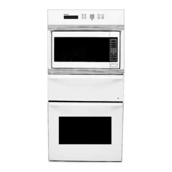
Thermador
SMW 272 B, SMW 272S, SMW 272W, SMW 272P
COOK
STOP
1
2
3
BAKE
OFF
TIME
TIME
4
5
6
SELF
TIMER 1
TIMER 2
BROIL
CLEAN
OVEN
CONVECTIO
CLOCK
7
8
9
CONVECTION
LIGHT
ROAST
0
SENSOR
SENSOR
COOK
REHEAT
POWER
POP
LEVEL
CORN
1
2
3
4
5
6
7
8
9
0
CLOCK
TIMER
MORE
QUICK
FUNCTION
/LESS
MIN
KEY
SERVING
KEEP
TURBO
/WEIGHT
WARM
DEFROST
STOP/RESET
START
for
®
Built-In Oven
Models:
Advertisement
Table of Contents
Troubleshooting

Related Manuals for Thermador SMW 272 B


Summary of Contents for Thermador SMW 272 B
- Page 1 CONVECTIO CLOCK CONVECTION LIGHT ROAST SENSOR SENSOR COOK REHEAT POWER LEVEL CORN CLOCK TIMER MORE QUICK FUNCTION /LESS SERVING KEEP TURBO /WEIGHT WARM DEFROST STOP/RESET START Thermador ® Built-In Oven Models: SMW 272 B, SMW 272S, SMW 272W, SMW 272P...
-
Page 2: Table Of Contents
https://appliancetechmanuals.com Oven Table of Contents Manual introduction Removing the O ven Temperature Sensor ....40 and Safety Precautions......1 – 2 Removing the Convection Bake Element ....41 Removing A Convection Fan Motor ......42 Microwave Oven Section: Specifications ..3 Removing A H alogen Lamp H older ......44 Removal from Cabinet ........... -
Page 3: Manual Introduction And Safety Precautions
Introduction SMW O ven Service Manual SMW SERVICE MAN UAL This manual contains information that is necessary for servicing the Thermador® built-in electric ovens, models: SMW 272B, SMW 272W, SMW 272S, SMW 272P T his manual, as well as the information contained in it, is designed to be used... - Page 4 https://appliancetechmanuals.com Introduction SMW Oven Service Manual IN TRODUCTION Model SMW 272 Model SMW 272 is desigmed with modular construction which makes it easier to service. The SMW O ven has a microwave section that is enclosed in the structure. The microwave section can be pulled out to service additionally, it has a warming drawer built into the structure below the microwave section.
-
Page 5: Microwave Oven Section: Specifications
https://appliancetechmanuals.com Microwave O ven Section SMW O ven Service Manual Microwave Oven Section COOK STOP BAKE TIME TIME SELF TIMER 1 TIMER 2 BROIL CLEAN OVEN CONVECTION CLOCK CONVECTION LIGHT ROAST SENSOR SENSOR COOK REHEAT POWER LEVEL CORN TIMER CLOCK MORE QUICK FUNCTION... -
Page 6: Removal From Cabinet
https://appliancetechmanuals.com Microwave Oven Section SMW O ven Service Manual To remove microwave section from cabinet: 1) Using both hands, pull the sides of the frame forward and unsnap the posts on both sides of the frame from the catches on the enclosure (See Illustrations, below). 2) Remove the two screws holding the microwave section in the enclosure. -
Page 7: W Arning: D Anbger Of H Igh Voltage
Microwave Oven Section SMW O ven Service Manual Thermador Customer Service 5551 McFadden Ave. H untington Beach, C A 92646 800/735-4328 Page 5... -
Page 8: Microwave Control Panel
https://appliancetechmanuals.com Microwave Oven Section SMW O ven Service Manual Microwave Control Panel Beep Sound W hen a pad is pressed correctly, a beep will be heard. If a pad is pressed and no beep is heard, the unit did not or cannot Display W indow accept the instruction. -
Page 9: Precautions To Avoid Exposure To Excessive Miocrowave Energy
https://appliancetechmanuals.com Microwave O ven Section SMW O ven Service Manual Page 7... -
Page 10: Circuit Test Procedure
https://appliancetechmanuals.com Microwave O ven Section SMW Oven Service Manual Page 8... - Page 11 https://appliancetechmanuals.com Microwave O ven Section SMW O ven Service Manual Page 9...
-
Page 12: To Use Function Pad
https://appliancetechmanuals.com Microwave O ven Section SMW O ven Service Manual To Use Function Pad Page 10... -
Page 13: Schematic D Iagrams
https://appliancetechmanuals.com Microwave O ven Section SMW O ven Service Manual SCH MAT IC DIAGRAM CAUTION: NOTE: Door is closed. Unit is not operating. HIGH VOLTAGE AREA Ground Chassis MAGNETRON CN701 THERMAL PRIMARY CUTOUT LATCH SWITCH CN703 CN702 E702 AC120V TURN OVEN 60Hz TABLE... -
Page 14: D Escription Of O Perating Sequence
https://appliancetechmanuals.com Microwave O ven Section SMW O ven Service Manual Page 12... - Page 15 https://appliancetechmanuals.com Microwave O ven Section SMW O ven Service Manual Page 13...
-
Page 16: Cautions To Be O Bserved W Hen Troubleshooting
https://appliancetechmanuals.com Microwave Oven Section SMW O ven Service Manual Page 14... - Page 17 https://appliancetechmanuals.com Microwave O ven Section SMW O ven Service Manual Page 15...
-
Page 18: Disassembly And Parts Replacement Procedure
https://appliancetechmanuals.com Microwave O ven Section SMW Oven Service Manual DISASSEMBLY AND PARTS REPLACEMENT PROCEDURE Page 16... - Page 19 https://appliancetechmanuals.com Microwave O ven Section SMW O ven Service Manual Page 17...
-
Page 20: Component Test Procedure
https://appliancetechmanuals.com Microwave O ven Section SMW Oven Service Manual Page 18... - Page 21 https://appliancetechmanuals.com Microwave O ven Section SMW O ven Service Manual Page 19...
-
Page 22: Measurements And Adjustments
https://appliancetechmanuals.com Microwave O ven Section SMW Oven Service Manual Page 20... -
Page 23: Procedure For Measuring Microwave Energy Leakage
https://appliancetechmanuals.com Microwave O ven Section SMW O ven Service Manual Page 21... -
Page 24: Troubleshooting Guide
https://appliancetechmanuals.com Microwave O ven Section SMW O ven Service Manual Page 22... - Page 25 https://appliancetechmanuals.com Microwave O ven Section SMW O ven Service Manual (Page 19). Page 23...
- Page 26 https://appliancetechmanuals.com Microwave O ven Section SMW Oven Service Manual Page 24...
- Page 27 https://appliancetechmanuals.com Microwave O ven Section SMW O ven Service Manual Page 25...
-
Page 28: Parts List Of D Igital Programmer Circuit & Schematic D Iagrams
https://appliancetechmanuals.com Microwave Oven Section SMW O ven Service Manual Page 26... - Page 29 https://appliancetechmanuals.com Microwave O ven Section SMW O ven Service Manual Page 27...
- Page 30 https://appliancetechmanuals.com Microwave O ven Section SMW Oven Service Manual Page 28...
- Page 31 https://appliancetechmanuals.com Microwave O ven Section SMW O ven Service Manual Page 29...
- Page 32 https://appliancetechmanuals.com Microwave Oven Section SMW O ven Service Manual N otes Page 30...
-
Page 33: W Arming Drawer Section
https://appliancetechmanuals.com W arming Drawer Section SMW O ven Service Manual W arming Drawer Section Page 31... -
Page 34: Replace Thermostat Or O N/Off Switch
https://appliancetechmanuals.com W arming Drawer Section SMW O ven Service Manual To Replace Thermostat or On/Off Switch A Remove drawer assembly ( See Figure 1.) Figure 1. REMOVIN G T H E DRAW ER To remove the drawer: To replace the drawer: •... -
Page 35: Replace H Eating Element
https://appliancetechmanuals.com W arming Drawer Section SMW O ven Service Manual Figure 3. Control Assembly Figure 4. H eating Element Screw (2) H eating Element 2. To replace heating element: a. Remove screws from element brackets in back of the liner. b D isconnect the wires from the bake element. -
Page 36: W Arming Drawer W Iring Diagram
https://appliancetechmanuals.com W arming Drawer Section SMW O ven Service Manual W arming Drawer W iring Diagram Figure 5. Page 34... -
Page 37: Lower Oven Section
https://appliancetechmanuals.com Lower O ven Section SMW Oven Service Manual Lower Oven Section COOK STOP BAKE TIME TIME SELF TIMER 1 TIMER 2 BROIL CLEAN OVEN CONVECTION CLOCK CONVECTION LIGHT ROAST SENSOR SENSOR COOK REHEAT POWER LEVEL CORN TIMER CLOCK MORE QUICK FUNCTION /LESS... -
Page 38: Symbols You W Ill See In The Manual
https://appliancetechmanuals.com Lower O ven Section SMW O ven Service Manual SYMBOLS YOU W ILL SEE IN THE MAN UAL The following symbols are provided throughout this operation and servicing of the oven, follow the instruc- manual. For reasons of personal safety and proper tions carefully each time you see one of the symbols. -
Page 39: Serial N Umber/Data Sticker Location
https://appliancetechmanuals.com Lower O ven Section SMW Oven Service Manual SERIAL N UMBER/DATA STICKER LOCATION Figure 6. COOK STOP BAKE TIME TIME SELF TIMER 1 TIMER 2 BROIL CLEAN OVEN CONVECTION CLOCK CONVECTION LIGHT ROAST Oven Control Panel, located above M icrowave Section D isplay W indow Control Panel D at a Plat e show ing... -
Page 40: Removing The Bake And Broil Elements, Catalyst
https://appliancetechmanuals.com Lower O ven Section SMW Oven Service Manual REMOVIN G THE BAKE & BROIL ELEMEN TS, CATALYST WARNING Turn off the electrical power circuit to the oven at the main junction box before ser- vicing this unit. CAUTION W hen you work on the oven, be careful when handling the sheet metal parts. - Page 41 https://appliancetechmanuals.com Lower O ven Section SMW Oven Service Manual Bracket Screws Catalyst Broil Element Brackets BACK OF LINER Figure 8 Bake Broil Element Element 2 Top Front Mounting Screws Figure 7 BACK OF LINER Connectors Bake Element Bracket Bracket Screws Figure 6 Page 39...
-
Page 42: Removing The O Ven Temperature Sensor
https://appliancetechmanuals.com Lower O ven Section SMW Oven Service Manual REMOVIN G THE OVEN TEMPERATURE SEN SOR WARNING Remove the racks from the oven. Turn off the electrical power circuit to the Remove the screws from the bracket and pull oven at the main junction box before ser- the oven temperature sensor forward until vicing this unit. -
Page 43: Removing The Convection Bake Element
https://appliancetechmanuals.com Lower O ven Section SMW Oven Service Manual REMOVIN G THE CON VECTION BAKE ELEMEN T WARNING Remove the racks from the oven. Turn off the electrical power circuit to the Remove the front screws from the left and oven at the main junction box before ser- right oven rack supports and remove the sup- vicing this unit. -
Page 44: Removing A Convection Fan Motor
https://appliancetechmanuals.com Lower O ven Section SMW Oven Service Manual REMOVIN G A CON VECTION FAN MOTOR WARNING Remove the hex nut from the front of the convection blade. N OTE: The nut has left-ro- Turn off the electrical power circuit to the tating threads. - Page 45 https://appliancetechmanuals.com Lower O ven Section SMW Oven Service Manual Oven Liner White Wire (#44) Brown Wire (#45) Fan Motor Bracket with Insulation Fan Motor Screws Convection Blade E-Ring Flat Washer Hex Nut (Left-Rotating Thread) Top Screw Top Screw Convection Baffle Bottom Screws Figure 11 Page 43...
-
Page 46: Removin G A Halogen Lamp Holder
https://appliancetechmanuals.com Lower O ven Section SMW O ven Service Manual REMOVIN G A HALOGEN LAMP HOLDER WARNING Pry the lamp holder out of the oven liner and cut the wires approximately 2 from the lamp " Turn off the electrical power circuit to the CAU T ION : Be careful not holder body. - Page 47 https://appliancetechmanuals.com Lower O ven Section SMW Oven Service Manual Halogen Lamp Lamp Holder Lamp Cover Figure 12 Page 45...
-
Page 48: Removing The Control Panel And D Isplay H Ead
https://appliancetechmanuals.com Lower Oven Section SMW O ven Service Manual REMOVIN G THE CON TROL PAN EL & DISPLAY HEAD b) Using both hands, pull the top of the con- WARNING trol panel forward and unsnap the posts on both sides of the panel from the catches Turn off the electrical power circuit to the in the subpanel (see inset 1). - Page 49 https://appliancetechmanuals.com Lower O ven Section SMW Oven Service Manual Inset 4 DISPLAY HEAD 888 888 88 88 Inset 1 CONV BAKE ROAST CONV BAKE ROAST DELAY START COOK TIMED CLEAN BROIL1 STEAM CLEAN BROIL2 STEAM STOP TIMER U L OVEN LOCK PREHEAT LOCK...
-
Page 50: Removing The O Ven Light Switch, The O Ven D Oor Latch Assembly, The H I-Temp Cutout
https://appliancetechmanuals.com Lower O ven Section SMW Oven Service Manual REMOVIN G TH E OVEN LIGH T SW ITCH , TH E OVEN DOOR LATCH ASSEMBLY, & TH E H I-TEMP CUTOUT WARNING To remove the oven door latch assem- bly (see inset 2): Turn off the electrical power circuit to the a) Use a 1/4 ratchet and a 1/4... - Page 51 https://appliancetechmanuals.com Lower O ven Section SMW Oven Service Manual Inset 1 Switch Wires TECH TIP!! Air Vent Grille You will need the following tools to remove the components: 1/4" ratchet Oven Light 1/4" thin-wall socket Switch Locking Arms # 2 Phillips O ffset Screwdriver OVEN DOOR LATCH SCREWS AIR VENT GRILLE AIR VENT GRILLE...
-
Page 52: Removing The Relay Board
https://appliancetechmanuals.com Lower O ven Section SMW Oven Service Manual REMOVIN G A RELAY BOARD WARNING Refer to Figure 16 below, and Figure 17 on the next page, for the following steps. Turn off the electrical power circuit to the oven at the main junction box before ser- Turn off the electrical power to the oven. -
Page 53: Lower Oven Relay Board
https://appliancetechmanuals.com Lower O ven Section SMW Oven Service Manual Lower Oven Relay Board OVLT BROIL BROIL2 Pnk (25) Yel (17) Blu (43) 2 Red Red (15) Red (42) Wht (20) Wht (19) (21 - 22) Blk (18) Blu (41) Blk (104) BAKE Yel (13) - Org (14) Org (16) -
Page 54: Removing The Air Switches
https://appliancetechmanuals.com Lower O ven Section SMW Oven Service Manual REMOVIN G THE AIR SW ITCH Refer to Figure 19 on the next page for the follow- WARNING ing steps. Turn off the electrical power circuit to the Turn off the electrical power to the oven. oven at the main junction box before ser- O pen the lower oven door. - Page 55 https://appliancetechmanuals.com Lower O ven Section SMW Oven Service Manual Mounting Screws Bracket AIR SWITCH Mounting Inset 3 Screws Bottom Trim Inset 2 Screw Bottom Trim Flange Inset 1 Side View Lower Oven Air Switch Figure 19 Air Switch Mounting Bracket Screws Page 53...
-
Page 56: Removing The Blower
https://appliancetechmanuals.com Lower O ven Section SMW Oven Service Manual REMOVIN G A BLOW ER To remove the lower blower (see Fig- WARNING ure 20): a) Remove the oven from the wall. Turn off the electrical power circuit to the oven at the main junction box before ser- b) Remove the rear panel from the oven. - Page 57 https://appliancetechmanuals.com Lower O ven Section SMW Oven Service Manual Blower Wire (24) To Blower Wire (23) To Upper Blower Motor Upper Blower Motor Blower Bracket Lower Blower Figure 20 Page 55...
-
Page 58: Removing The Lamp Transformer & The Lower O Ven Stalled Fan Relay
https://appliancetechmanuals.com Lower O ven Section SMW Oven Service Manual REMOVIN G THE LAMP TRAN SFORMER & THE LOW ER OVEN STALLED FAN RELAY WARNING To remove an oven stalled fan relay (see Figure 22): Turn off the electrical power circuit to the a) Remove the screws and disconnect the oven at the main junction box before ser- wires from the relay terminals. -
Page 59: Removing The Lower O Ven D Oor
https://appliancetechmanuals.com Lower O ven Section SMW Oven Service Manual REMOVIN G AN OVEN DOOR To remove the door: Refer to Figure 30 for the following steps. O pen the door to its fully open position. a) Grasp the door by the sides toward the back and raise the front of the door sev- Raise the hinge latch over the hook on each eral inches (there will be some resistance... -
Page 60: Removin G The Oven Door Gasket
https://appliancetechmanuals.com Lower O ven Section SMW Oven Service Manual REMOVIN G THE OVEN DOOR GASKET CAUTION W orking from one end of the gasket to the other, carefully pull the clips that are attached W hen you work on the oven, be careful to the gasket out of the holes in the oven when handling t he sheet met al part s. -
Page 61: Removing The O Ven D Oor Components
https://appliancetechmanuals.com Lower O ven Section SMW Oven Service Manual REMOVIN G THE OVEN DOOR COMPON EN TS CAUTION To remove any of the oven door components, remove the oven door from the oven (see W hen you work on the oven, be careful Page 57). -
Page 62: Removing The "S" O Ven Module
https://appliancetechmanuals.com Lower O ven Section SMW Oven Service Manual REMOVIN G THE LOW ER OVEN MODULE (27") Convection Kit—#35-00-661 WARNING Turn off the electrical power to the oven. To make servicing easier, remove the oven Turn off the electrical power circuit to the door (see Page 57). -
Page 63: Troubleshooting
https://appliancetechmanuals.com Lower O ven Section SMW O ven Service Manual TROUBLESHOOTIN G TESTIN G TH E COMPON EN TS WARNING TO AVOID ELECT RICAL SH OCK • DISCO N N ECT T H E PO W ER T O T H E APPLIAN CE BEFO RE SERVICIN G. •... - Page 64 https://appliancetechmanuals.com Lower O ven Section SMW O ven Service Manual T H E CON VECT ION FAN MOTOR T H E LAMP T RAN SFORMER Refer to Page 42 to access the convection fan Refer to Pages 56 to access the lamp transformer. motor.
- Page 65 https://appliancetechmanuals.com Lower O ven Section SMW O ven Service Manual T H E OVEN DOOR LAT CH ASSEMBLY If the reading is not correct, remove and The oven door latch locks the oven door during the replace the switch. cycle (see the illustration at the bottom of CLEAN the next column for the various latch positions).
- Page 66 https://appliancetechmanuals.com Lower O ven Section SMW O ven Service Manual T H E BAKE ELEMEN T THE BROIL ELEMEN T Refer to Page 38 to access the bake element. Refer to Page 38 to access the broil element. W ith no power applied, remove the wires W ith no power applied, remove the wires from the terminals of the bake element.
-
Page 67: Connectors
https://appliancetechmanuals.com Lower O ven Section SMW O ven Service Manual CON N ECTORS W ire H arness No Pin A ribbon connector is used to connect the touch @ #4 control board to the display head. The ribbon has eighteen carbon traces (conductors) that transfer 18 17 16 15 14 13 12 11 10 9 8 7 6 5 4 3 2 1 To Touch Control Board the signals from control board connector P1 to... - Page 68 https://appliancetechmanuals.com Lower O ven Section SMW O ven Service Manual CON N ECTOR J 5 CON N ECTOR P2 Connector P2 On Touch Control Board Upper Oven Not Used Door Latch Switch To Connector J1-2 On Relay Board To Connector J1-2 On Display Head To Connector J1-1 On Display Head...
- Page 69 https://appliancetechmanuals.com Lower O ven Section SMW O ven Service Manual CON N ECTOR J 8 CON N ECTORS J 9 & J 10 Not Used Not Used Lower Oven Door Latch Switch Lower Oven Sensor 1050 Ω Door Switch N.O. Not Used Lock Switch N.O.
-
Page 70: Convection Oven Relay Board
https://appliancetechmanuals.com Lower O ven Section SMW O ven Service Manual Convection Oven Relay Board LowerOven — #16-10-660 Connector J10 Upper Oven Sensor Connector J9 Connector J7 Connector J2 Lower Oven Sensor Lower Oven Relay Board Display Head Connector J8 Lower Oven Door Latch K9 K6 Connector J5... -
Page 71: Oven Relay Board Matrix
https://appliancetechmanuals.com Lower O ven Section SMW O ven Service Manual Oven Relay Board Matrix Relay Item Bake Broil Convect. Element Convect. Motor None Fans Both Oven Lights Oven Door Latch Page 69... - Page 72 https://appliancetechmanuals.com Lower O ven Section SMW O ven Service Manual ERROR CODE MESSAGES Error Example Cause Corrective Action Code Replace main relay Element supervisor is enabled. Bad main relay board. board. O ver temperature detected. Intermittent temperature Replace temperature sensor or bad main relay sensor.
-
Page 73: Error Code Messages
https://appliancetechmanuals.com Lower O ven Section SMW O ven Service Manual Error Corrective Cause Example Code Action Check all power con- Communication error detected by Lower oven relay board nections to the oven display head. not powered up. relay boards and the display head. -
Page 74: Electronic O Ven Control Test Modes
https://appliancetechmanuals.com Lower O ven Section SMW O ven Service Manual ELECTRON IC OVEN CON TROL TEST MODES H AN DLIN G T H E BOARDS Touch Control Board The Touch Control Board and the D isplay H ead H andle the Touch Control Board only by the edges are subject to failure if static electricity is trans- of the glass and the plastic frame. - Page 75 https://appliancetechmanuals.com Lower O ven Section SMW O ven Service Manual up, provided no other key is pushed prior to STO P The test mode is designed to allow quick testing of TIME. The control will immediately enter the test the control inputs and outputs. mode.
- Page 76 https://appliancetechmanuals.com Lower O ven Section SMW O ven Service Manual KEY PRESSED ACT IO N Stop T ime Speaker will beep. Clock All the display segments are lit. Cook T ime Any error codes stored in the EEPRO M will be displayed. The time digits will display the last display head error code.
-
Page 77: Sequence Of O Peration
https://appliancetechmanuals.com Lower O ven Section SMW O ven Service Manual SEQUEN CE OF OPERATION Lower Oven Bake Cycle — Bake Preheat & Bake Mode Press the BAKE keypad and select an oven temperature and the following events will occur on the relay board: •... -
Page 78: Broil Cycle - Broil Preheat And Broil Mode
https://appliancetechmanuals.com Lower O ven Section SMW O ven Service Manual Broil Cycle — Broil Preheat & Broil Mode Press the BRO IL keypad and select an oven temperature and the following events will occur on the relay board: • Line Relay closes. -
Page 79: Convection Cycle - Convection Preheat And Convection Mode
https://appliancetechmanuals.com Lower O ven Section SMW O ven Service Manual Convection Cycle – Convection Preheat & Convection Mode Press the CO N VECTIO N keypad and select an oven temperature and the following events will occur on the relay board: •... -
Page 80: Convection Roast Preheat
https://appliancetechmanuals.com Lower Oven Section SMW Oven Service Manual Convection Roast Cycle — Convection Roast Preheat Press the CO N VECTIO N RO AST keypad and select an oven temperature and the following events will occur on the relay board: • Line Relay closes. -
Page 81: Convection Roast Cycle
https://appliancetechmanuals.com Lower O ven Section SMW O ven Service Manual Convection Roast Cycle N O TE: The Convection Roast cycle is a continuation of the Convection Roast Preheat cycle. Press the CO N VECTIO N RO AST keypad and the following events will occur on the relay board: •... -
Page 82: Self-Clean Cycle - Preheat Below 840
https://appliancetechmanuals.com Lower O ven Section SMW O ven Service Manual ˚ Self-Clean Cycle — Preheat Below 840 Press the SELF-CLEAN keypad and select a self-clean time period and the following events will occur on the relay board: • Line Relay closes. -
Page 83: Self-Clean Cycle
https://appliancetechmanuals.com Lower O ven Section SMW O ven Service Manual Self-Clean Cycle N O TE: The Self-Clean cycle is a continuation of the Self-Clean Preheat cycle. Press the SELF-CLEAN keypad and the following events will occur on the relay board: •... - Page 84 Thermador Customer Support Call Center, 5551 McFadden Avenue, H untington Beach, C A 92649 • 800/735-4328 ECO 12436 • 94-30-008A • © 2000 Thermador • Litho U.S.A. 2/00...
Need help?
Do you have a question about the SMW 272 B and is the answer not in the manual?
Questions and answers