TSI Instruments 4040 Operation And Service Manual
General purpose thermal mass flow meter
Hide thumbs
Also See for 4040:
- Operation and service manual (24 pages) ,
- Operation and service manual (17 pages)

Related Manuals for TSI Instruments 4040


Summary of Contents for TSI Instruments 4040
- Page 1 General Purpose Thermal Mass Flow Meter Model 4040/4043/4045 Operation and Service Manual P/N 1980339, Revision M April 2022 www.tsi.com...
- Page 2 Start Seeing the Benefits of Registering Today! ® Thank you for your TSI instrument purchase. Occasionally, ® releases information on software updates, product enhancements and new products. By registering your ® instrument, TSI will be able to send this important information to you.
- Page 3 Flow Meter Model 4040/4043/4045 Operation and Service Manual P/N 1980339, Revision M April 2022 U.S. & INTERNATIONAL TSI Instruments Ltd. (UK) Sales and Customer Service: Sales and Customer Service: (800) 680-1220 / +1(651) 490-2860 +44 (0) 1494 459200 Fax: +1(651) 490-3824...
- Page 5 Copyright TSI Incorporated / 2002-2022 / All rights reserved. Address TSI Incorporated / 500 Cardigan Road / Shoreview, MN 55126 USA W A R N I N G ® Incorporated flow meters employ a heated platinum sensor. They should not be used with flammable or explosive gasses or mixtures.
- Page 6 EXCLUSIVE REMEDY SHALL BE THE RETURN OF THE PURCHASE PRICE DISCOUNTED FOR REASONABLE WEAR AND TEAR OR AT SELLER’S OPTION REPLACEMENT OF THE GOODS WITH NON-INFRINGING GOODS. TO THE EXTENT PERMITTED BY LAW, THE EXCLUSIVE REMEDY OF THE USER OR BUYER, AND THE LIMIT OF SELLER'S LIABILITY FOR ANY AND ALL LOSSES, INJURIES, OR DAMAGES CONCERNING THE GOODS (INCLUDING CLAIMS BASED ON CONTRACT, NEGLIGENCE, TORT, STRICT LIABILITY OR OTHERWISE) SHALL BE THE RETURN OF GOODS TO SELLER AND THE REFUND OF THE...
-
Page 7: Table Of Contents
CONTENTS 1 UNPACKING AND PARTS IDENTIFICATION ....... 1 2 SETTING-UP ................... 3 Supplying Power ................3 Connecting Filter and Flow Tubes ..........4 RS232 Configuration and Operation ..........4 Configuration Software ..............5 3 OPERATION ..................7 Overview ..................7 ON/OFF Switch ................ - Page 8 (This page intentionally left blank)
-
Page 9: Unpacking And Parts Identification
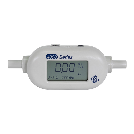
Mass Flow Meter, 0.75 inch inlet/outlet 4045 Computer Cable 1303583 Analog Cable 1303584 Filter 22 mm ISO-taper (for Model 4040) 1602292 3/8” Female NPT (for Model 4043/45) 1602300 AC Adapter 100 to 240 V, N. America NEMA 5-15 plug, grounded 8918-NA... - Page 10 Parts Identification Figure 1-1 Model 4040/4043/4045 Mass Flow Meter 1. On/Off Switch 4. DC Power Input 2. Display 5. Flow Inlet 3. Mounting Inserts (2) 6. Computer Serial Interface and Analog Output and Optional Power Input Connector Chapter 1...
-
Page 11: Setting-Up
Chapter 2 Setting-Up Supplying Power The flow meter can be powered in one of two ways: through the power jack using the supplied AC adapter or through the mini-DIN connector. The DC power input connector is shown below along with the power requirements. -
Page 12: Connecting Filter And Flow Tubes
Connecting Filter and Flow Tubes The Models 4040/4043/4045 have an exposed thermal flow sensor, which must be protected from foreign matter and particles in the gas ® flow. TSI has supplied a filter, which should be connected to the inlet of the flow meter;... -
Page 13: Configuration Software
Configuration Software ® has several software utilities to help you communicate with your flow meter to change parameters and to obtain flow data. You can download the latest versions of these at no charge from our web site: https://tsi.com 1. If you only want to change one or more of the operating parameters shown in Table 3 (above), the easiest way is to use the software utility called “TSI setup.”... - Page 14 3. If you plan to develop a more sophisticated program for data collection and control using LabVIEW™ program, you can download a demonstration program called “Real-time Demo Program” and the source code “Source Code for Real-time Demo Program.” This program is intended to be a basic demonstration program and not a practical laboratory tool.
-
Page 15: Operation
Recommended warm-up time of the flow meter is 5 minutes. Flow Rate Measurement Flow rate data can be obtained from the Models 4040/4043/4045 through the LCD display, RS232 serial port or the linearized analog output. The analog output is a 0 to 10 volt DC linear signal representing 0 to 300 Std L/min (Model 4043: 200 Std. -
Page 16: Temperature Measurement
This is a calculated measurement performed by the flow meter and is only available using the RS232 serial port. Volume is not displayed on the LCD display. Refer to the Models 4040/4043/4045 RS232 Serial Command Set manual for instructions on using the volume function. -
Page 17: Maintenance
Never run liquids through the flow meter and never touch the sensor with a brush. Dust or other deposits on the flow sensor will degrade the 4040/4043/4045 flow meter’s flow accuracy. C A U T I O N The flow meter must be switched off for cleaning. - Page 18 (This page intentionally left blank) Chapter 4...
-
Page 19: Troubleshooting
Chapter 5 Troubleshooting Table 4 lists the symptoms, possible causes, and recommended solutions for common problems encountered with the flow meter. If the symptom is not listed, or if none of the solutions solves the ® problem, please contact TSI Customer Support at 1-800-680-1220 or 651-490-2860. - Page 20 (This page intentionally left blank) Chapter 5...
-
Page 21: A Specifications
Appendix A Specifications* Flow Measurement Measurement Range Models 4040/4045 ..0 to 300 Std L/min. Model 4043 only .... 0 to 200 Std L/min. Accuracy Air, O ......2% of reading or 0.05 Std L/min, whichever is greater. , Air/O mixtures .. - Page 22 Storage, Ambient ....-20 to 60°C Physical Dimensions External Dimensions ..See Diagram Tube Adapters ....Model 4040: 22 mm male ISO Taper (Inlet & Outlet) Model 4043: ½ inch straight Model 4045: ¾ inch straight Weight ......180 grams Flow Body Material ...
- Page 23 For analog output, accuracy offset increases from 0.05 to 0.1 Std L/min. To achieve accuracy, analog zero needs to be changed from factory defaults to be 0.020V or higher. See Appendix Add uncertainty of 0.2 kPa for every 10°C away from 21.1°C. *Specifications subject to change without notice.
- Page 24 Specifications...
- Page 25 Specifications...
- Page 26 (This page intentionally left blank) Appendix A...
-
Page 27: B Standard Flow Rate Vs. Volumetric Flow Rate
Volumetric flow rate is the true volume flow of the gas exiting the flow meter. In some instances, volumetric flow rate rather than standard flow rate may be of interest. To display volumetric flow rate, the Models 4040/4043/4045 will multiply the standard flow measurement by the following density correction factor: ... - Page 28 (This page intentionally left blank) Appendix B...
-
Page 29: C Optimal Use Of The 4000/4100 Series Analog
Appendix C Optimal Use of the 4000/4100 Series Analog Out Capability Introduction Incorporated’s 4000/4100 series flow meters have a feature that ® allows you to determine the flow rate based on a 0-10 Volt Analog out signal. This feature has programmable options that can improve its use accuracy. -
Page 30: Considerations When Needing To Read Zero And Low Flow Accurately
Considerations When Needing to Read Zero and Low Flow Accurately If the application requires accurate flow measurement at or near zero flows then it is recommended that the zero flow voltage be changed from its factory default of 0 volts to 100 mV. This is due to a slight offset of the ground voltage that could be interpreted as a low-level flow. -
Page 31: Considerations For Setting The Span Flow Voltage
Considerations for Setting the Span Flow Voltage If the application does not require the flow meter to read up to its span flow then it is recommended that the analog span be set to the maximum limit that is required by the application. - Page 32 TSI Incorporated – Visit our website www.tsi.com for more information. Tel: +1 800 680 1220 India Tel: +91 80 67877200 Tel: +44 149 4 459200 China Tel: +86 10 8219 7688 France Tel: +33 1 41 19 21 99 Singapore Tel: +65 6595 6388 Germany Tel: +49 241 523030 ©2022 TSI Incorporated P/N 1980339 Rev M...
Need help?
Do you have a question about the 4040 and is the answer not in the manual?
Questions and answers