
Related Manuals for TSI Instruments Alnor AirGard 405


Summary of Contents for TSI Instruments Alnor AirGard 405
- Page 1 Fume Hood Monitor Alnor ® AirGard ® Owner’s Manual P/N 116159093, Rev. 12 May 2022 GlobalTestSupply www. .com Find Quality Products Online at: sales@GlobalTestSupply.com...
- Page 2 Start Seeing the Benefits of Registering Today! Thank you for your TSI ® instrument purchase. Occasionally, TSI ® releases information on software updates, product enhancements and new products. By registering your instrument, TSI ® will be able to send this important information to you. GlobalTestSupply www.
- Page 3 LIMITATION OF WARRANTY AND LIABILITY (effective April 2014) (For country-specific terms and conditions outside of the USA,) Seller warrants the goods, excluding software, sold hereunder, under normal use and service as described in the operator's manual, to be free from defects in workmanship and material for 24 months, or if less, the length of time specified in the operator's manual, from the date of shipment to the customer.
-
Page 4: Table Of Contents
TABLE OF CONTENTS General Description ............2 Setup .................. 4 Installation ................. 6 General ................6 Tools Required ..............6 Procedure ................ 7 Calibration ................. 9 Equipment ............... 9 Procedure ................ 9 Step by Step Operation ..........11 Alarm Acknowledgment ..........11 Alarm Test .............. -
Page 5: General Description
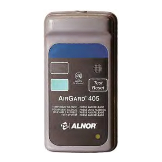
General Description The AirGard ® 405 monitor is designed to continuously monitor airflow through fume hoods. This permanently installed device provides both visual and audible alarms to alert you of abnormal airflow conditions after the instrument is calibrated for the particular installation. - Page 6 1. MOUNTING Two screws secure the monitor to the SCREWS back plate which is then secured to the fume hood. 2. AIR INLET A portion of the air coming into the hood passes through the air inlet and across the flow sensors. 3.
-
Page 7: Setup
Setup The AirGard ® 405 fume hood monitor contains several configuration options. Two connectors provide access to remote control devices and firmware configuration jumpers. Observe the back of the monitor. Locate the two connectors at the left-center of the printed circuit board marked J3 and JP1. - Page 8 Pole 1 of JP1 is used to select the relay configuration. Without the jumper installed, the relay is Normally Closed (NC) during normal airflow and Normally Open (NO) during an alarm condition. Installing a shorting jumper across pole 1 will cause the relay to be Normally Open (NO) during normal airflow and Normally Closed (NC) during an alarm condition.
-
Page 9: Installation
Installation General Installation of the AirGard ® 405 monitor requires several holes to be drilled in the fume hood using the back plate as a template. To monitor face velocity, the air outlet port at the back of the AirGard ®... -
Page 10: Procedure
N O T I C E If the monitor is to be installed in a hood with Hardiboard™ fiber-cement side panels or similar material, use special drill bits designed for glass and other hard, abrasive materials. W A R N I N G Older hoods may contain asbestos. - Page 11 Step 6: Connect the supplied air hose between the sidewall adapter (figure 4) and the flow tube through the back plate orifice (figure 3). Secure hose firmly and cut to length as necessary to prevent accidental kinks and bends which can affect calibration.
-
Page 12: Calibration
Calibration Field calibration must be performed since each hood installation is unique. W A R N I N G Calibration of this instrument should only be performed by qualified personnel. Proper guidelines for monitoring any ventilation apparatus are established on the basis of toxicity or hazards of the materials used, or the operation conducted within the ventilation apparatus. - Page 13 Step 4: Adjust fume hood airflow to the low flow setpoint (as described in Step 3). One method to lower the face velocity of the hood is to close the volume damper (if available) in the ductwork. W A R N I N G This method is only used as a temporary condition to set the low flow point.
-
Page 14: Step By Step Operation
Step-By-Step Operation Alarm Acknowledgment The horn and red indicator will turn on approximately six seconds after an alarm condition is detected. To mute the horn, press and release the TEST/RESET button. Note that after an alarm condition has been detected, the red indicator will stay on. -
Page 15: Maintenance & Troubleshooting
APPENDIX A: Maintenance & Troubleshooting Maintenance The outside of the AirGard 405 monitor may be wiped clean ® with mild soap (dish washing detergent) and water on a damp cloth to remove finger marks, oils or residue. DO NOT use abrasives or solvents. DO NOT immerse the monitor or allow liquids to enter the case. -
Page 16: Service Policy
Symptom Check HORN SILENCE WILL An alarm condition must be NOT STAY ON continuously present before the horn can be silenced. If flow conditions fluctuate near the alarm setpoint, the alarm will automatically reset itself. Action should be taken to bring fumehood airflow to proper condition, or recalibrate the alarm setpoint. -
Page 17: Specifications
AIRGARD 405 MONITOR SPECIFICATIONS ® Instrument Dimensions 6.05" high x 3.15" wide x 1.8" deep (15.4 x 8.0 x 4.6 cm) Instrument Weight 8 oz (0.23 kg) Shipping Weight 1 lb. 8 oz (0.68 kg) Green Indicator 0.75" x 0.5" (1.9 x 1.3 cm) Red Indicator 0.75"...
Need help?
Do you have a question about the Alnor AirGard 405 and is the answer not in the manual?
Questions and answers