TSI Instruments 4043 Operation And Service Manual
Thermal mass flowmeter
Hide thumbs
Also See for 4043:
- Operation and service manual (24 pages) ,
- Operation and service manual (32 pages)

Related Manuals for TSI Instruments 4043


Summary of Contents for TSI Instruments 4043
- Page 1 GENERAL PURPOSE THERMAL MASS FLOWMETER MODEL 4040/4043/4045 OPERATION AND SERVICE MANUAL P/N 1980339, REVISION J FEBRUARY 2016 GlobalTestSupply www. .com uality Products Online at: sales@GlobalTestSupp...
- Page 2 THERMAL MASS FLOWMETER MODEL 4040/4043/4045 OPERATION AND SERVICE MANUAL P/N 1980339, REVISION J FEBRUARY 2016 U.S. & INTERNATIONAL TSI Instruments Ltd. (UK) Sales and Customer Service: Sales and Customer Service: (800) 874-2811 / +1(651) 490-2811 +44 (0) 1494 459200 Fax:...
-
Page 3: Table Of Contents
CONTENTS CHAPTERS UNPACKING AND PARTS IDENTIFICATION ......1 SETTING-UP ................. 3 Supplying Power ................3 Connecting Filter and Flow Tubes ..........4 RS232 Configuration and Operation ..........4 Configuration Software ..............5 OPERATION ................. 7 Overview ..................7 ON/OFF Switch ................7 Warm-up Time ................ -
Page 4: Chapters
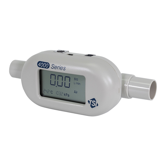
1303583 Analog Cable 1303584 Filter 22 mm ISO-taper (for Model 4040) 1602292 3/8” Female NPT (for Model 4043/45) 1602300 AC Adapter 100 to 240 V, N. America NEMA 5-15 plug, grounded 8918-NA 100 to 240 V, Europlug, CEE 7/16, grounded... - Page 5 Parts Identification Figure 1-1 Model 4040/4043/4045 Mass Flowmeter 1. On/Off Switch 4. DC Power Input 2. Display 5. Flow Inlet 3. Mounting Inserts (2) 6. Computer Serial Interface and Analog Output and Optional Power Input Connector Chapter 1 GlobalTestSupply www.
-
Page 6: Setting-Up
Chapter 2 Setting-Up Supplying Power The flowmeter can be powered in one of two ways: through the power jack using the supplied AC adapter or through the mini-DIN connector. The DC power input connector is shown below along with the power requirements. Power Supply: 7.5 VDC ±... -
Page 7: Connecting Filter And Flow Tubes
Connecting Filter and Flow Tubes The Models 4040/4043/4045 have an exposed thermal flow sensor, which must be protected from foreign matter and particles in the gas flow. TSI has supplied a filter, which should be connected to the inlet of the flowmeter; however, any filter will work as long as it has a minimum efficiency of 99.9%. -
Page 8: Configuration Software
Configuration Software TSI has several software utilities to help you communicate with your flowmeter to change parameters and to obtain flow data. You can download the latest versions of these at no charge from our web site: 1. If you only want to change one or more of the operating parameters shown in Table 3 (above), the easiest way is to use the software utility called “TSI setup.”... -
Page 9: Operation
LCD display, RS232 serial port or the linearized analog output. The analog output is a 0 to 10 volt DC linear signal representing 0 to 300 Std L/min (Model 4043: 200 Std. L/min) (analog output scaling is user selectable). Refer to the RS232 Serial Command Set manual for instructions on how to obtain flow data through the serial port. -
Page 10: Temperature Measurement
LCD display. Refer to the Models 4040/4043/4045 RS232 Serial Command Set manual for instructions on using the volume function. TSI instruments defines standard conditions as 21.1°C (70° F) and 101.3 kPa (14.7 psia, 1 bar). Chapter 3 GlobalTestSupply www. -
Page 11: Maintenance
Re-certification To maintain a high degree of confidence in the measurements made by the Models 4040/4043/4045, TSI recommends that you return the instrument to TSI every 12 months for re-certification. For a nominal fee, we will recalibrate the unit and return it to you with a certificate of calibration and US National Institute of Standards Technology (NIST) traceability. -
Page 12: Troubleshooting
Chapter 5 Troubleshooting Symptom Possible Causes Corrective Action No display. Unit not switched on. Switch on the unit. No power to Plug in AC adapter or instrument. check power source on mini-DIN connector. Temperature Temperature sensor is This is normal. Once reads high at being heated from the flow exceeds 1 Std... -
Page 13: Specifications
Appendix A Specifications* Flow Measurement Measurement Range Models 4040/4045 ..0 to 300 Std L/min. Model 4043 only .... 0 to 200 Std L/min. Accuracy Air, O ......2% of reading or 0.05 Std L/min, whichever is greater , Air/O mixtures .. - Page 14 Physical Dimensions External Dimensions ..See Diagram Tube Adapters ....Model 4040: 22 mm male ISO Taper (Inlet & Outlet) Model 4043: ½ inch straight Model 4045: ¾ inch straight Weight ......180 grams Flow Body Material ... PolyCarbonate Computer Interface Connector ......
- Page 15 Specifications GlobalTestSupply www. .com uality Products Online at: sales@GlobalTestSupp...
- Page 16 Appendix A GlobalTestSupply www. .com uality Products Online at: sales@GlobalTestSupp...
-
Page 17: Standard Flow Rate Vs. Volumetric Flow Rate
Since thermal flow sensors are sensitive to changes in air density and air velocity, all thermal flowmeters indicate flow rates with reference to a set of standard conditions. For TSI instruments, standard conditions are defined as 21.1° C (70° F) and 101.3 kPa (14.7 psia). Other manufacturers may use different values.
Need help?
Do you have a question about the 4043 and is the answer not in the manual?
Questions and answers