Table of Contents
Advertisement
Advertisement
Table of Contents

Subscribe to Our Youtube Channel
Related Manuals for Henkel Loctite EQ RC40


Summary of Contents for Henkel Loctite EQ RC40
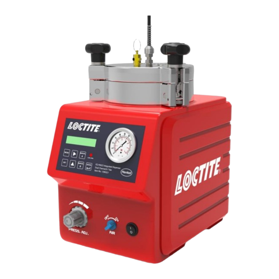
- Page 1 EQ RC40 Integrated Dispenser IDH 2814025 Operating Manual...
-
Page 2: Table Of Contents
Table of Contents Please Observe the Following ....................3 Emphasized Sections ......................3 For Your Safety ........................3 Unpacking and Inspection ....................3 Packing List ........................... 4 Features ..........................4 Field of Application (Intended use) ................... 4 Description ........................... 5 2.1 Theory of Operation ........................ -
Page 3: Please Observe The Following
Please Observe the Following Emphasized Sections Warning! Refers to safety regulations and requires safety measures that protect the operator or other persons from injury or danger to life. Caution! Emphasizes what must be done or avoided so that the unit or other property is not damaged. -
Page 4: Packing List
Field of Application (Intended use) The Loctite EQ RC40 Integrated Dispenser combines both a controller and a reservoir into a single unit. The controller provides 2 independent digital timing channels that provide control of 2 pneumatic outputs. These outputs can be used to... -
Page 5: Description
Description 2.1 Theory of Operation The Loctite EQ RC40 Integrated Dispenser is connected to an external electrical and pneumatic supply. The system is equipped with a 0 to 7 bar (0-100psi) pressure regulator that regulates the preset dispensing pressure of the reservoir and controls the dispensing during the selected dispensing time. - Page 6 Time Mode: 1. Press the footswitch to activate the system. 2. The dispense timer will be activated and start to dispense with preset time. 3. After the dispensing timer has reached the preset dispensing time, the dispensing will be stopped. Continuous Mode: 1.
-
Page 7: Control Panel (Front & Back Of Controller)
2.2 Control Panel (Front & Back of controller) -
Page 8: Technical Data
1. Valve Pressure Relief 14. Tank Pressure Gauge 2. Reservoir/Lid Fitting 15. Tank Pressure Regulator 3. Display 16. Channel A ON Output 4. Mode Switch 17. Channel A OFF Output 5. Right Arrow Switch 18. Channel B ON Output 6. Manual Switch for Channel A 19. -
Page 9: Installation
Installation Before using the equipment for the first time check it carefully for signs of external damage. If any shipping damage is found DO NOT USE THE EQUIPMENT – return it to your supplier immediately. 4.1 Environmental and Operating Conditions Keep the pneumatic hose to the dispense valve as short as possible for optimum dispense control. -
Page 10: Connecting The Unit
Use flexible pneumatic hoses and Loctite supplied product feedlines to prevent unnecessary loads on the fitting and to ensure compatibility. Keep all fittings tight. No direct sunlight; no UV light. No condensing humidity. Avoid direct connect with water. 4.2 Connecting the Unit Use only the cable and hose sets supplied. -
Page 11: Filling And Refilling The Product Reservoir
If two dispense valves are used, remove blanking plug from the reservoir lid and replace with additional reservoir/tube fitting. 4.3 Filling and Refilling the Product Reservoir Warning! Never fill the product directly into the reservoir! The pneumatic and safety devices would become clogged and therefore ineffective! Warning! Before loosening the reservoir locking knobs (6), the EQ RC40 Integrated Dispenser must be depressurized (pressure-free)! -
Page 12: Operation
• Loosen the reservoir knobs and remove the lid. • Check that there is no condensed moisture at the bottle or the sensor surface. • Place the bottle in the bottle holder (see the right figure). • Check that the product bottle inserted in the bottle holder is pressed again the level sensor. - Page 13 Switch (11): To confirm the setting and save. Switch (6): In “Run: Manual” mode, press and hold for manual purging the adhesive for Channel A without displaying or changing parameters. Switch (9): In “Run: Manual” mode, press and hold for manual purging the adhesive for Channel B without displaying or changing parameters.
- Page 14 5.3 Start Up the System: 1. Turn the “POWER” on (the position marked “l”) (13). The display (3) will turn on. 2. If necessary, open the valve or regulator that controls the air inlet to supply pneumatic pressure to the system. 3.
- Page 15 5.7 Set: Time (Auto) Mode Set the dispensing time for Channel A and Channel B in “Run: Auto” mode. 1. Press to select Channel A, the left most digit for Channel A will start to flash. 2. Press for numbering change on the flashing digit (0.01 – 99.99). 3.
- Page 16 5.10 Set: Low Level Mode 1. Press , the setting for Low Level mode start to flash. 2. Press for switching between “OFF”, “LAMP” and “LAMP + STOP”. 3. After completed setting, press to save and exit. Notice: OFF: Only digital output from XS1 LAMP: Digital output from XS1 + LED Light on control panel LAMP + STOP: Digital output from XS1 + LED Light on control panel + System Stop 5.11 Set: Lock-Out Mode...
- Page 17 Before adjusting the Level Sensor 1. Remove the plastic cap from the backside of reservoir. 2. Empty a bottle of the product you use. 3. Leave as much residue in the bottle as is required in order to prevent air getting into the product feed line. 4.
-
Page 18: Application Hints
Application Hints As with all adhesives, performance depends on conditions of use. Suggestions or recommendations contained herein are for guidance only since actual conditions of use are outside the supplier’s control. 6.1 Shutdown for Longer Periods of Non-use (>recommended idle time) •... - Page 19 When the controller is operational, the unit can be LED does not light. LED defect. used until repaired by Henkel Service. Switch the power switch to the position O (OFF). Tighten the Plug on the socket XS1(20 screws of the plug. Switch the No start signal or 21), Start signal is loose.
- Page 20 Dispensing valve not Check the dispensing valve correctly connected or (see instruction manual for No product, too little or too defective. dispensing valve). much product Product reservoir not Check product reservoir. switched on. Product reservoir is empty. Refill product reservoir. Increase the supply pressure The desired pressure is not Supply pressure...
-
Page 21: Care And Maintenance
Care and Maintenance 8.1 Care -Occasionally the O-ring at the reservoir lid should be lubricated with silicone grease. This will prolong the life of the O-ring. Notice: Clean hands after application of grease to ensure surfaces to be bonded are clean. -Clean the sensor surface as required. -
Page 22: Accessories And Spare Parts
Accessories and Spare Parts Item Description IDH# Spare Parts Reservoir/tube Tank Fitting, ¼ inch NPT x ¼ inch Tubing 360636 Footswitch 88653 ¼ inch O.D. Black PE Teflon Lined feedline Tubing (10mtr/33ft length) 142646 Tank Lid O-ring for Reservoir 478505 Pressure Safety Relief Valve 360462 Anti-Bubbler Kit, 2 Adapters &... -
Page 23: Diagrams
Diagrams XS1 Start via Footswitch, additional Empty Signal and Ready Signal. Warning! Never connect external voltage on pin1 or pin9! NEVER short pins 3 and 4, nor 6 and 7 together, permanent board damage will result. -
Page 24: Warranty
Henkel, the use of products, parts or attachments which are not manufactured by Henkel, no claim shall be allowed. No Products shall be returned to Henkel for any reason without prior written approval from Henkel. Products shall be returned freight prepaid, in accordance with instructions from Henkel. -
Page 25: Declaration Of Conformity
THIS SECTION SETS FORTH EXCLUSIVELY ALL OF LIABILITY FOR HENKEL TO THE PURCHASER IN CONTRACT, IN TORT OR OTHERWISE IN THE EVENT OF DEFECTIVE PRODUCTS. WITHOUT LIMITATION OF THE FOREGOING, TO THE FULLEST EXTENT POSSIBLE UNDER APPLICABLE LAWS, HENKEL EXPRESSLY DISCLAIMS ANY LIABILITY WHATSOEVER FOR... - Page 26 Deutchland www.equipment.loctite.com ® and ™ designate trademarks of Henkel Corporation or its affiliates. ® = registered in the U.S. and elsewhere. © Henkel Corporation. All rights reserved. Data in this operation manual is subject to change without notice. Manual P/N: n/a, Rev A, Date: 10/18/2021...
Need help?
Do you have a question about the Loctite EQ RC40 and is the answer not in the manual?
Questions and answers