
Related Manuals for Henkel Loctite RB10


Summary of Contents for Henkel Loctite RB10
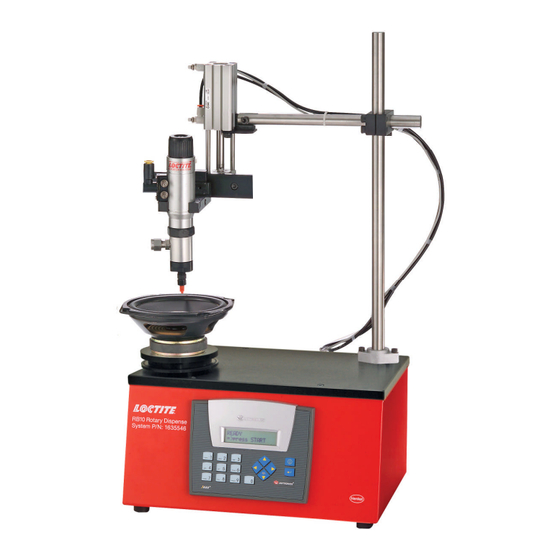
- Page 1 EQUIPMENT Operation Manual Loctite RB10 Rotary Dispense System Part Number 1635546...
-
Page 2: Table Of Contents
Table of Contents Please Observe The Following 1.1 Emphasized Sections 1.2 For Your Safety 1.3 Inspection 1.4 Items Supplied 1.5 Features 2 Description 2.1 Control Panel 2.2 Integration Panel 3 Technical Data 4 Installation 5 Operation 5.1 Theory of Operation 5.2 Controller Set Up 5.3 Mounting Plate 5.4 Valve and Syringe Dispenser Integration... -
Page 3: Please Observe The Following
Please Observe The Following Emphasized Sections Warning! Refers to safety regulations and requires safety measures that protect the operator or other persons from injury or danger to life. Caution! Emphasizes what must be done or avoided so that the unit or other property is not damaged. -
Page 4: Items Supplied
Items supplied (1) Rotary Dispense System (1) Foot Switch (1) Power Supply with Cord (1) Instruction Manual Features Integrated Solution –plug and play with Loctite valves, reservoirs, and Syringe Systems Digital Control of rotation, dispense start, dispense stop and delays ... -
Page 5: Integration Panel
Integration Panel (Back of Controller) Technical Data Attribute Value Dispense Pattern Circles or Arcs in a Circular Pattern Slide Stroke 0 –2”(0 –50 mm) Rotation Range 0 –999 Degrees Rotation Speed 5 to 55 RPM Maximum Part Height 12”(305 mm) Maximum Part Diameter 18”(475 mm) Maximum Part Weight... -
Page 6: Installation
Installation Before using the tool for the first time check it carefully for signs of external damage. If any shipping damage is found DO NOT USE THE TOOL - return it to your supplier immediately. Assemble the stand to the main control unit by attaching the vertical mounting pole (the longer bar supplied) into the vertical support bracket on the control of the unit. -
Page 7: Operation
Operation Theory of Operation After turning on the unit, press the footswitch or ENTER button to activate the system. The advancing slide will start to extend and the rotary disc will start to rotate with the preset speed. The advancing slide will activate the proximity sensor when it reaches the preset position. -
Page 8: Controller Set Up
Controller Set Up Display Step Enter Toggle To Unlock Press 1 & 3 Together For Three Seconds Notice: Upon start-up, the system will be in operator lockout mode. To unlock the controller, press 1 & 3 simultaneously for three seconds. To return to operator lockout mode simply turn system off;... - Page 9 Press Step and the Display will change to Speed: 10 RPM Dist: 90 deg To change the speed (revolutions per minute), type the desired speed with key pad, then press ENTER To change the distance (in degrees) that product will dispense, type the desired distance using the key pad, then press ENTER Notice: The distance setting determines how far the rotation motor receives power and is intended to be an aid in initial set up not as an absolute setting of rotation.
-
Page 10: Mounting Plate
Mounting Plate The drawing below shows the RB10 Rotary Dispense System mounting plate. This through holes on the mounting plate can be used for fixture alignment and the threaded ¼- 20 holes can be used to secure the fixture. -
Page 11: Valve And Syringe Dispenser Integration
Valve and Syringe Dispenser Integration ® The Loctite RB10 Rotary Dispense System is designed to be used with syringes, cartridges, single acting product valves and double acting product valves. To integrate these dispense systems please use the following instructions: 5.4.1 98009 Light Cure, 98013 Cyanoacrylate and VA10 Micro Dispense Valves Must be purchased separately: ... -
Page 12: 5.4.3 Syringe Or Cartridge Dispensing
Adjust the height and position of the mounting bracket to the approximate position desired. To adjust the position, loosen the screws on the clamp blocks counter clockwise, set the position and then secure by turning the screws clockwise. Caution! It is important to ensure that the dispense tip will not crash with the mounting plate, fixture or part. -
Page 13: Slide Adjustment
Slide Adjustments The speed controls on the slide can be adjusted to increase or decrease the speed that the slide advances or retracts. The speed should be set so that the slide moves at a controlled rate. This may need to be adjusted to account for more weight on the slide or to change the slide advance / retract time. -
Page 14: Troubleshooting
Troubleshooting Before proceeding with any repair or maintenance operation disconnect the tool from the main electricity supply. Symptom Possible Corrective Action(s) The “ POWER”does not turn Plug the unit in “ ON” Set the “ POWER”button “ ON”position The system will not pressurize. 1. -
Page 15: Accessories
Accessories Syringe Dispenser Accessories: Loctite Part Number Accessory Syringe Cartridge 10 ml 30 ml 55 ml 300 ml Syringe Dispenser (Required) 883976 883976 883976 883976 3 ¾”Mounting Rail (required) 98328 98328 98328 98328 Mounting Bracket (required) 98316 98316 98316 98318 Syringe Adapter (required) 98320 Dispense Tip Connectors (required) -
Page 16: Warranty
Diadema/SP, Brazil www.loctite.com ® and ™ designate trademarks of Henkel Corporation or its affiliates. ® = registered in the U.S. and elsewhere. © Henkel Corporation, 2009. All rights reserved. Data in this operation manual is subject to change without notice.
Need help?
Do you have a question about the Loctite RB10 and is the answer not in the manual?
Questions and answers