Table of Contents
Advertisement
Quick Links
Advertisement
Table of Contents

Related Manuals for Henkel Loctite


Summary of Contents for Henkel Loctite
- Page 1 Henkel Corporation MMD System 1000 Machine Manual...
- Page 2 SAFETY • • Always wear safety glasses when operating. Do not operate if any of the SYSTEM 1000 • components are missing or damaged. 100-PSI maximum inlet air pressure. Use a known • Danger Labels: Indicate an regulated dry air source only. •...
- Page 3 Safety Precautions This manual provides installation, operation, and maintenance instructions for Loctite meter, mix, and dispense machines. Read this manual before you install and operate your machine. Use your machine only as directed. Safety Terms within our manuals Cautions are given where failure to observe the instruction could result in damage to the equipment, associated equipment, and/or process.
-
Page 4: Table Of Contents
Table of Contents WARRANTY..............................1 SYSTEM 1000 GENERAL DESCRIPTION ....................2 DIAGRAMS OF COMMON VALVES AND PARTS................3 MACHINE FEATURES..........................5 REASSEMBLY AND INSTALLATION ....................6 ADJUSTING THE SHOT SIZE ........................7 LOADING THE MACHINE WITH MATERIALS ..................8 PRIMING THE MATERIAL VALVES .....................9 PHASING THE PUMPS ..........................10 RATIO CHECK ............................11 RATIO ADJUSTMENT ..........................12 DAILY OPERATION..........................13... -
Page 5: Warranty
WARRANTY PROPRIETARY EQUIPMENT AND COMPONENTS MANUFACTURED BY SELLER The warranties contained herein are not made in regard to auxiliary equipment and components (see Section below). Unless otherwise specifically stated in writing, warranties are limited to the following: All proprietary goods designed, manufactured and sold by Seller are guaranteed against defective workmanship or material for a period of three (3) years after date of shipment from the factory, provided the goods were operated under the condition for which they were sold. -
Page 6: System 1000 General Description
It is recommended that this manual be read thoroughly by all personnel charged with the responsibility of operating, maintaining, or cleaning the equipment. CAUTION Due to the precise nature of the SYSTEM 1000, we recommend consulting Henkel’s technical service department @ (800) LOCTITE before making any major adjustments. -
Page 7: Diagrams Of Common Valves And Parts
Diagrams of Common Valves and Parts The below diagrams depict common 2-way and 3-way ball valves and the handle styles are likely to be encountered on this machine. Also, shown in the following diagrams are miscellaneous parts likely to be used by this machine. These diagrams are for reference only and may not show all types and styles of ball valves and other parts. - Page 8 Figure 2-Common Valves and Parts Cont.
-
Page 9: Machine Features
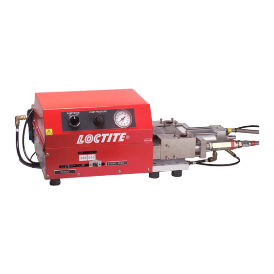
Machine Features Logic Features: PUMP MODE Switch The PUMP MODE switch is used to provide power to the machine. OFF: The pumps will not operate when pressing the start device. ON: The pumps will operate when the start device is pressed. PUMP AIR PRESSURE Gauge and Regulator The PUMP AIR PRESSURE regulator controls how much air pressure is fed to the air cylinder, driving the pumps. -
Page 10: Reassembly And Installation
Reassembly and Installation The Posiratio Mini SYSTEM 1000 machine is completely factory assembled and tested. However, due to packing convenience, some on-site reassembly may be required. 1. Turn the PUMP MODE switch to the OFF position. 2. Close all ball valves. 3. -
Page 11: Adjusting The Shot Size
Adjusting the Shot Size The RETRACT limit switch enables the machine logic to retract the air cylinder and pumps when tripped. Follow these instructions to adjust the position of this switch for your desired shot size. Retract Limit Switch Loosen the knurled knob securing the Figure 3-Stroke Adjust RETRACT limit switch. -
Page 12: Loading The Machine With Materials
Loading the Machine with Materials A Gravity Feed Tank uses the force of gravity to draw material into the pump. Test all machine features and controls before loading material for the first time. 1. Remove the lid from the material reservoir. 2. -
Page 13: Priming The Material Valves
Priming the Material Valves Load the machine with materials described above before proceeding. 1. Turn the PUMP MODE to OFF and adjust the pump air pressure to 0 psi. 2. Set the STROKE ADJUST for a large shot. 3. Position a waste container under the material nozzles. 4. -
Page 14: Phasing The Pumps
Phasing the Pumps 1. Turn the PUMP MODE to OFF and adjust pump air pressure to 0 psi. 2. Place clean containers under the material nozzles. 3. Turn the PUMP MODE to ON and slowly increase pump air pressure until the machine begins to cycle. -
Page 15: Ratio Check
Ratio Check Phase the pumps before proceeding. Since your machine is designed to process two components, it is important to monitor the actual ratio of "A" material to "B" material that is being dispensed. Metering pumps are mechanical devices that have seals, O-rings, pistons, metering tubes, check valves and a variety of components that are subject to wear and/or failure. -
Page 16: Ratio Adjustment
Ratio Adjustment NOTE: If your System 1000 is a fixed ratio machine continue to the next page. If the ratio samples obtained in the Ratio Check section are very close to each other, but outside the manufacturer tolerances, then you need to adjust the ratio. 1. -
Page 17: Daily Operation
Daily Operation 1. Turn the PUMP MODE to OFF and adjust the pump air pressure to 0 psi. 2. Position waste containers under the material nozzles. 3. Turn the PUMP MODE to ON. 4. Press and hold the start device. 5. -
Page 18: Shutdown
Shutdown 1. Turn the PUMP MODE to OFF. 2. Adjust the pump air pressure to 0 psi. 3. Disconnect the main air supply. 4. Bleed air from the machine by pushing off-center the valve stem on the bottom of the air filter. -
Page 19: Piston Replacement
Piston Replacement 1. Set the STROKE ADJUST for a full shot. 2. Turn the PUMP MODE to OFF. 3. Reduce the pump air pressure to 0 psi. 4. Place clean containers beneath the material nozzles to collect recyclable materials. 5. Turn the PUMP MODE to ON 6. -
Page 20: Periodic Maintenance
Periodic Maintenance Daily Air Filter Check air circuit water trap valve and release any water, as necessary, through the base outlet. Air Lubricator Check that bowl has oil level above the bottom of the pipe within the bowl and refill as necessary. Bleed off main air supply before removing bowl. -
Page 21: Troubleshooting
Troubleshooting If problems develop in the operation of the SYSTEM 1000 meter, mix, and dispense machine, refer to the following list of symptoms and causes. PUMPING (After Satisfactory Start-Up) PROBLEM CAUSE SOLUTION Pump stalling and no material Blocked mixer. Turn off air supply and remove being pumped despite adequate hoses from mixer. - Page 22 PUMPING (After Satisfactory Start-Up) PROBLEM CAUSE SOLUTION Pumps drawing material back down Check valve stuck open. Remove check valve and clean or from hose. replace. (continued) Air in material. Being drawn into Remove check valve and fitting in pump from behind check valve. front of pump.
- Page 23 PNEUMATIC CIRCUIT (After Satisfactory Start-Up) PROBLEM CAUSE SOLUTION Pumps remain in forward position Front roller trip switch not With a screwdriver end, push roller and will not return (units including functioning. Switch roller position down. If pumps return, adjust pump stroke alignment only). may need adjusting.
- Page 24 PNEUMATIC CIRCUIT (After Satisfactory Start-Up) PROBLEM CAUSE SOLUTION (continued) Four-way air cylinder directional If main input air signal comes from control valve needs servicing or the starting device then the four- replacement. way control valve is not changing over. Remove and service (ask for technical advice).
-
Page 25: Additional Information
ADDITIONAL INFORMATION If this machine is equipped with a desiccant air dryer. This assembly dries the makeup air that enters the tank as the material level decreases. READ THE INSTRUCTIONS ON THE DESICCANT AIR DRYER CANISTER PRIOR TO USE AND ON THE INITIAL STARTUP. Vent holes are to be put in both ends of the canister before operating the machine.
Need help?
Do you have a question about the Loctite and is the answer not in the manual?
Questions and answers