
Subscribe to Our Youtube Channel
Related Manuals for Avios C-130V2


Summary of Contents for Avios C-130V2
- Page 1 INSTRUCTION MANUAL For intermediate to advanced pilots Please read this manual carefully before operating this plane.
-
Page 2: Safety Instructions
SAFETY INSTRUCTIONS 1. Please read this manual carefully and follow the instructions before you use this product. 2. This airplane is not a toy, due to it's advanced flying qualities it is only suitable for experienced pilots. If you are a novice then please only operate with the assistance of an experienced pilot. 3. -
Page 3: Specifications
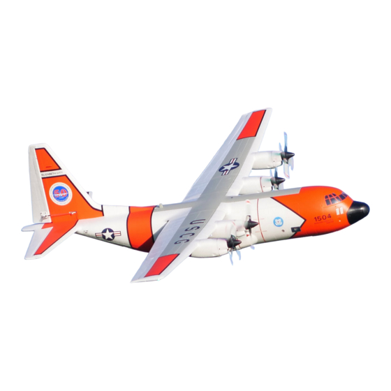
The Avios C-130 V2 is available in two brand new color schemes, the classic US Coast Guard scheme of hi-viz orange and white with scale decals, or a typical civilian cargo plane scheme in red, white, and blue. - Page 4 CONTENTS 1. FUSELAGE 8. ACCESSORY PACK 2. MAIN WING 9. DETAIL PARTS 3. HORIZONTAL STABILIZER 10. SCALE ACCESSORIES 4. VERTICAL STABILIZER 11. SPINNER BACKPLATES 5. PROPELLERS 12. METAL TAIL ATTACHMENT RODS 6. AUXILIARY TANKS 13. DISPLAY CARGO RAMP 7. WING JOINER...
- Page 5 ASSEMBLY 1. Select the main fuselage body. 2. Install the metal rods into the carbon sleeves at the rear of the fuselage as shown. 3. Metal rods shown in place.
- Page 6 4. Get the rear fuselage/horizontal stabilizer section ready. 5. Slide the assembly onto the metal rods as shown.. 6. Locate the assembly fully into the rear of the fuselage so that there is no gap.
- Page 7 7. Install the vertical stabilizer spigots into the corresponding slots in the rear of the fuselage assembly. 8. Ensure the vertical stabilizer is fully seated into the slots in the fuselage assembly. 3mm x 25mm 3mm x 20mm 9. Use the supplied 3mm x 20mm, and 3mm x 25mm screws to lock the vertical stabilizer to the fuselage assembly.
- Page 8 10. Install the supplied rudder control horn and pushrod as shown in the picture above. Please note: The Z link goes to the servo horn, and the ball link to the rudder horn. 11. Slide through the fuselage the carbon fiber main wing spar. 12.
- Page 9 13. Slide both wings onto the main wing spar. 14. Push both wings up against the fuselage wing roots, make sure the electrical connectors on the wings line up and plug in correctly. 3mm x10mm 15. Insert the 4 off 3mm x 10mm screws into the fuselage wing roots as shown, if possible, use a Hex key with ball end to...
- Page 10 16.The propeller adapters are factory fitted, worth checking at this point that they are tight and secure. 17. Install the propellers onto the shaft and spinner backplate, secure in place with the supplied Hex screws. Once again, apply some thread lock to the screw threads for security..
- Page 11 18. Install the outboard flap pushrod linkages to the flaps as shown. Ensure the Z link goes to the servo horn, and the ball link goes to the flap horn. 19. Install the elevator pushrod linkage to the elevator as shown. Once again, ensure the Z link goes to the servo horn, and the ball link to the elevator horn.
- Page 12 Figure 1 Figure 2 20. Connect the UBEC cables to the power cables in the fuselage as shown in Figures 1 & 2 above. Please pay careful attention to the polarity, and also ensure that all the pins are fully seated into the socket.
- Page 13 RADIO CONTROL SETUP Please also study your computer radio instruction manual carefully for the programming and the proper setup of each function on this airplane. Flaps setting procedure: NOTE: Please do not have the flap control linkages attached until you have the radio set up done. Once you have set up your radio you may install the control linkages and fine tune the flap control surface travels evenly on both sets of flaps on both wings.
- Page 14 12. Double check to ensure all the flap control surfaces are operating in the same manner. 13. Pics #1-3 below shows the inboard and outboard flaps when fully deployed. Pic #1 Pic #2 Pic #3 CARGO BAY DOOR SETTING PROCEDURE: 1.
- Page 15 For a way switch setup Adjust the end point so that with the switch position selecting the door closed the door is flush with the fuselage and there is no buzzing from the servo. Flick the switch to the door down position and adjust the end point so that the door just misses the ground.
- Page 16 Put the C-130 on a plane stand. With landing wheels down (gear switch should be in gear down position). Replace the depleted battery with a fresh battery pack and it to the power input cables. Cycle the gear switch once. Only the nose gear door will open and close again (Nose wheels and main wheels will remain in the down position).
- Page 17 SCALE DETAIL PARTS ASSEMBLY: The following pictures show the fitting of the windshield wipers.
- Page 18 The following pictures show the fitting of the pitot tubes.
- Page 19 The following pictures show the fitting of the antenna's.
- Page 20 The following pictures show the fitting of the dew point sensor.
- Page 21 Cargo Door Ramp (Display Only). Note: The cargo door ramp is for display purposes only on the ground, please do not use it when flying the C-130.
- Page 22 PROPELLERS CHECK. Direction for the rotation of the propellers CAUTION: Please stay away from the spinning propellers at all times.
-
Page 23: Recommended Control Throws
RECOMMENDED CONTROL THROWS... - Page 24 CG LOCATION The recommended C of G (center of gravity) position is 65mm measured from the leading edge of the wing at the center of the fuselage. The model should balance slightly nose down when balanced on the finger tips underneath the wing on the C of G point. Do not fly your C-130 with a rearward C of G, this means any further back than the 65mm.
-
Page 25: Recommended Accessories
RECOMMENDED ACCESSORIES... -
Page 26: Spare Parts
SPARE PARTS... - Page 27 SPARE PARTS...
- Page 28 APEX CE SPECIALISTS LIMITED UK REP M1 4HT, UK APEX CE SPECIALISTS LIMITED...
Need help?
Do you have a question about the C-130V2 and is the answer not in the manual?
Questions and answers