Radionics D9000 Series Operation And Installation Manual
Control/communicator
Hide thumbs
Also See for D9000 Series:

Related Manuals for Radionics D9000 Series


Summary of Contents for Radionics D9000 Series
- Page 1 D9000/D7000 Series Control/Communicator Operation and Installation Manual 74-07692-000-C 4/97 www.PDF-Zoo.com firealarmresources.com...
-
Page 2: Preface
Text marked with a diamond (♦) indicates that Preface this function or feature is available on the D9412 This manual addresses the operation and and D7412 only. installation of the D9412, D9112, D7412, and The table below provides an overview of the D7212 Control/Communicators only, and should differences between the D9000/D7000 Series not be used in conjunction with the D9112B1 or... -
Page 3: Fcc Notices
Series Control/Communicators, please contact case the user will be required to correct the Radionics Customer Service for repair and/or interference at his own expense. warranty information. If the trouble is causing Part 68... -
Page 4: Table Of Contents
Table of Contents Battery Discharge/Recharge Schedule ..16 Preface ..............2 Charging Status and Low Battery LEDs ... 17 FCC Notices ............. 3 Charging Status LED (Yellow) ..... 17 Part 15 ............3 Low Battery LED (Red) ........ 17 Part 68 ............3 Power Outputs ............. - Page 5 Self Diagnostics ..........45 Wiring Data Expansion Loops to Phone Line Trouble .......... 46 POPEX Modules ......... 29 Communications Failure ........47 POPIT Sensor Loops ........29 Problems Programming the Panel ....48 POPIT Module Point Assignments ....29 Problems with Points ........49 D8128C OctoPOPIT Module ......
- Page 6 Figures and Tables Figure 1: System Configuration ..............7 Figure 2: Enclosure Mounting ..............11 Figure 3: Reset Pin ..................12 Figure 4: Charging and Battery LEDs ............17 Figure 5: Connecting D8132 Modules ............19 Figure 6: Relays for Terminals 7 and 8 and Ground Start ....... 19 Figure 7: RJ31X Wiring ................
-
Page 7: Introduction
. Figure 1: System Configuration Areas and Accounts Points The Radionics D9412/D9112 Control/ The system supports up to eight separate areas. You can assign all points to a single area or Communicator panel provides up to 246 spread them out over up to eight areas. -
Page 8: Communicator
♦ ♦ ♦ ♦ ♦ Communicator Keyswitch The Control/Communicator uses a built-in digital You can arm and disarm any of the eight communicator to send reports to the receiver. The available areas with maintained or momentary panel transmits reports in either the Modem IIIa closure devices such as keyswitches and sub- or BFSK format. -
Page 9: Emi/Lightning Transient Protection
• UL Smoke Detector Compatibility Technogram (33284) Programming • Point Chart Label (79-06660-000) Use either the Radionics D5200 Programmer or • Eight D105BL 1k W end-of-line resistors the Remote Account Manager (RAM III) to program the D9000/D7000 Series Control/ • Two 14", 18 AWG, color-coded battery leads Communicators. -
Page 10: Listings And Approvals
Factory Mutual (FM) Listings and Approvals Approved by Factory Mutual. The D9000/D7000 Literature Pack includes the D9000/D7000 Series Approved Applications Not listed. Compliance Guide (74-07693-000). Refer to this guide for additional guidelines for installing the Burglary Control/Communicator in UL and Fire specific applications. -
Page 11: Installation
The drain wire for the shielded Mount the Control/Communicator assembly in cable must have continuity from terminal 10 on any of the Radionics enclosures listed below. the panel to the end of the wire run. If continuity is Refer to the D9000/D7000 Approved... -
Page 12: Installing The Assembly
Installing the Assembly Place the assembly over the inside back of the enclosure, aligning the large rectangular RESET PIN openings of the mounting skirt with the LOCKE D (CLOS ED) Operation Monitor Pulses When Normal mounting hooks of the enclosure. Slide the Flickers When Ringing assembly down so it hangs on the hooks. -
Page 13: Install Modules And Relays
See Ground Start in the Telephone Install the Point Chart Label Connections section. Radionics recommends you fill out the Point Make the Telephone Connections Chart Label (79-06660-000) provided in the literature pack and install it on the inside of the See Telephone Connections . -
Page 14: Testing The System
If you test a device, and the panel doesn’t Testing the System respond, there may be a problem with the device, After finishing the installation and programming the wiring, the POPIT ID setting, or the of the panel, make a complete functional test of programming for the point. -
Page 15: Power Supply
Check with AHJ on Primary (AC) Power Circuit mounting transformers on specific circuits. A 16.5 VAC, 40 VA internally fused transformer (Radionics model D1640) is the primary power Secondary Power source. The AC power circuit provides 1.9 Amps Terminals of rectified AC power. -
Page 16: Battery Supervision
BATTERY LOW terminals 4 and 5. A shorted battery may report in the Radionics’ Modem IIIa ™ generate WATCHDOG RESET reports. Communication Format. It transmits a TROUBLE ZN 9 report in the BFSK format. -
Page 17: Charging Status And Low Battery Leds
• Yellow LED flashing once per minute Charging Status and Low Battery LEDs The yellow LED normally flashes once per Charging Status LED (Yellow) minute as the system checks the battery. The yellow LED shows the charging status of the •... -
Page 18: Power Outputs
Continuous Power Outputs of the power outputs, the panel transmits a Terminals BATTERY LOW or BATTERY MISSING for Radionics’ Modem IIIa ™ Communication Format, or TROUBLE ZN 9 for BFSK. One thermal circuit breaker protects Terminal 3 - Auxiliary Power and Terminal 24 - ZONEX Power Continuous Current Draw and the Expansion Port (J4). -
Page 19: Optional Relays Required
NOTE: C om b ined To tal D isp ers ed C urrent of 7.0 a m p s @ 12 V D C Figure 5: Connecting D8132 Modules The Radionics defaults set relay A (terminal 6) Optional Relays Required as a Steady Alarm Bell output and relay A... -
Page 20: Terminals 6 And 7
Relay Installation Fire System Power Formula Power down the system before inserting the To calculate the current available at terminals 6 D136 relays. The plug-in relays are shorter than and 7 for fire and combined fire/burglary systems: the sockets they plug into. See Figure 6. You can Add together the current draws for all install them in either the left or right end of the devices connected to terminals 3, 8, 24, and... -
Page 21: Telephone Connections
Telephone Connections Registration Phone Cord Connection The Radionics D9412, D9112, D7412, and Connect one end of a D161 (8') or D162 (2') D7212 Control/Communicator panels are Telephone Cord to the TELCO Cord connector, registered with the Federal Communication J3, located on the bottom left corner of the panel. -
Page 22: Phone Line Test Points
The panel stops monitoring the phone line during Relay Installation its phone line trouble response. If the response Power down the system before inserting the includes sending a report, the panel does not D136 relay into socket K6/J5. The relay socket is resume monitoring until the report is in the lower left corner as shown in Figure 6. -
Page 23: Operation
Set the ring count above 2 on answering surge protection for the two incoming phone machines: The line's RAM Monitor feature may lines. The black lead also is the ground reference not operate correctly if you connect an answering for the AC LED. machine with a ring count of less than 2 rings, to Connect the green lead from the D928 to a phone line used by the D928 module. -
Page 24: D928 Status Leds
D928 Status LEDs Phone Line Fail LEDs Two yellow phone line status LEDs (one for the Four LEDs mounted on the front edge of the primary phone line, one for the secondary phone D928 module show the status of AC power for the line) light up when phone line voltage drops panel, the status of the two phone lines, and below 4.5 to 7.5 VDC without a corresponding 8-... -
Page 25: On-Board Points
Therefore point response time ranges from 300 supervise is limited only by the resistance on the milliseconds to 4.5 seconds. The Radionics loop. The total resistance for wire length and default for Debounce Count is 2. -
Page 26: Off-Board Points
Off-Board Points POPIT modules monitor their sensor loops for Point (ZONEX) Bus three conditions, loop normal, loop open, and D9412/D9112 Terminals loop shorted. They report these three conditions to the D9412/D9112. D7412/D7212 Terminals The D9412/D9112 uses point programming to interpret the sensor loop information reported by On the D9412/D9112, you can use POPIT (Point the POPITs and make the appropriate system of Protection Input Transponder) modules to... -
Page 27: Figure 12: Connecting The D8125 Popex To The Panel
Figure 12: Connecting the D8125 POPEX to the Panel D9000/D7000 Series Operation & Installation Manual Page 27 74-07692-000-C 4/97 www.PDF-Zoo.com firealarmresources.com... -
Page 28: Installing The D8125 Popex Module
Wiring POPITs to the Data Expansion Loop Installing the D8125 POPEX Module Use one 2-wire data expansion loop or distribute Save the POPIT Label Sheets: The D8125 is the POPITs on up to three loops. Setting DIP packaged with two sets of POPIT label sheets. switches on the POPIT modules assigns them to One is marked for use with the D9412/D9112 . -
Page 29: Wiring Data Expansion Loops To Popex Modules
Modem IIIa format. Ω end-of-line resistor [D106F) included with each POPIT. Radionics recommends you use twisted-pair wire in all POPEX/POPIT installations for both the data expansion loop wiring and the POPIT sensor loops. Run wires away from AC sources to prevent AC induction. -
Page 30: D8128C Octopopit Module
POPIT Labels Listing Off-board points for the D9412 and D9112 are The D8128C OctoPOPIT Module is UL listed for numbered 9 to 127 and 129 to 247 (D7412 and Local or Police Connected Burglary Alarm, D7212 use points 9-75 only). The D9412/D9112 Central Station Burglary Alarm, and Household reserves points 128 and 248 for internal use. -
Page 31: Wiring Octopopits
28 on the panel if you are going to transmits to the panel separately. assign point numbers from 9 to 120 (or 9 to Radionics recommends you use twisted-pair wire 75 if you are using a D7412/D7212) to this for the OctoPOPIT sensor loops to avoid EMI OctoPOPIT. -
Page 32: Figure 14: D8128C Octopopits
ZO N EX B US 1 Z O N EX B US 1 Sw itch "0" O N Sw itch "0" O FF (P o in ts 9 - 7 2 ) (P o in ts 7 3 - 1 2 0) F irst A dd res s on Z O N E X B us 1 L ast A ddress on Z O N E X B us 1 B us 1... - Page 33 ZONEX 1 D8128C ZONEX 2 ZONEX 1 D8128C ZONEX 2 D8128C D8128C Switches Switches Sensor Sensor D9412 D9412 D9412 D9412 Loop Point Point Loop Point Point On On On On Off On On On On On On Off Off On On Off On On Off On Off On Off On On On Off Off...
-
Page 34: Off-Board Relays
Off-Board Relays Warning: Relay outputs may activate while D8129 OctoRelay setting the OctoRelay switches or programming the panel. You may wish to disconnect The D8129 OctoRelay allows you to add relay equipment connected to relay outputs while outputs to your system in groups of eight. On the performing these functions. -
Page 35: D811 Arm Status Relay Module
D 8 1 2 5 P O P E X GN D C on tr ol/C o m m u nica tor O U T P an el A UX Z O N E X O U T 1 Z O N EX IN 1 DATA D 8 1 2 9 O C TO R E L AY S FO R R E L AY N U M BE R S 1 TO 6 4 . -
Page 36: Installation
Wiring Connections Installation Power down the panel to connect D811 modules You can install the D811 in the enclosure with the as shown in Figure 16. Note that the D811 for panel (see Figure 2) or in an adjacent enclosure relay number 53 connects to ZONEX 1. -
Page 37: Arming Devices
D9112 Program Entry Guide (74-07695-000) for a complete description of addresses. Terminals Table 5 shows the correct switch setting for each The Radionics Command Center is a 4-wire address. powered device used to arm and disarm areas, annunciate complete system status, initiate... -
Page 38: D268/D269 Independent Zone Control D279 Independent Zone Control
PA N E L D 8 1 3 2 C O N N E C T IO N S + 12 V D C + 1 2 V D C P O W E R + D ATA C O M M O N D ATA B U S A D ATA D A TA B U S B... -
Page 39: Keyswitch
Keyswitch Operation Keyswitch Maintained Contact If you program the point the keyswitch is Description connected to for a maintained contact, an open You can connect a maintained or momentary on the arming circuit arms the area. All faulted contact arming station (keyswitch) to master arm/ points are force armed, regardless of the entry in disarm any of the areas in the system. -
Page 40: Sdi Devices
The panel sends an SDI failure report to the receiver if it fails to communicate with the printer The Radionics D9131A Parallel Printer Interface interface, and SERVC PRINTER displays at the is a 4-wire powered device used to connect a Command Center. -
Page 41: D9210B Access Control Module
Switch Settings Switches on the D9210B assign a unique address (1 to 8) to each module. See the The Radionics D9210B Access Control Interface D9210B Program Entry Guide (74-07618-000) is a 4-wire powered device providing for a complete description of address switch connections for an access door point and door settings. -
Page 42: Programmer And Accessory Connections
Programmer and Accessory Connections Programmer Connector (J7) The procedure below shows you how to connect F O R P R O GR A M M IN G PA N E L and disconnect the programmer. Refer to D5200 Programmer Operation Manual (74-06176-000) for complete information on using the D5200 programmer. -
Page 43: D9412 Faceplate
FACEPLATE SHIELD HOOKS 17-05823-002 D 9412 OPERATION LEDs Off When Normal C H AR G IN G STATU S LED MONITOR LED Y EL Dig ital Alarm, Comm unicator Tra nsmitter Op eratio n Monitor Charging Status (Yellow ) Pulses W hen Normal G R N Flicke rs W h en Ringing Low Battery... -
Page 44: Quick Reference Terminal Description
Quick Reference Terminal Description Terminal Name Description 1, 2 CLASS 2 Connect 16.5 VAC, 40 VA transformer for primary power supply. TRANSFORMER Supplies up to 1.4A at 10.2 VDC to 13.9 VDC to powered devices. Use terminal 9 + AUX POWER for common. -
Page 45: Troubleshooting Guide
Pressing "ESC" does not silence the buzzer. You COMM FAIL ROUTE# 1 (or 2, 3, 4) - Route must return the panel to Radionics for repair. Communications Failure Attach a Radionics Return Tag or call Customer FAIL ROUTE # appears in Command Center Service for a return authorization. -
Page 46: Phone Line Trouble
SERVC KEYPAD - Supervised Command Pressing "ESC" silences the buzzer. The display clears when the panel detects a normal phone Center Missing line. See Phone Line Monitor in the Telephone When the panel loses contact with a supervised Connections section for a complete description. Command Center, SERVC KEY PAD appears at other Command Centers connected to the panel. -
Page 47: Communications Failure
The receiver is not Verify that the receiver is compatible with the format the panel is call and provides an initial compatible with the panel’s using (either BFSK or Radionics Modem IIIa ™ Communications “handshake” transmission format. Format). See Phone in the D9000/D7000 Series Program Entry acknowledgment, but does Guide (74-07695-000). -
Page 48: Problems Programming The Panel
Problems Programming the Panel Before attempting to program the panel, you should be familiar with the basic operation of the D5200 programmer. See the D5200 Operation Manual (74-06176-000). If you still experience problems, check for the symptoms below. Symptom Diagnosis Remedy The programmer displays The programmer is not... -
Page 49: Problems With Points
Problems with Points (Continued) Symptom Diagnosis Remedy One or more points The sensor loop is open, Remove the sensor loop from the panel or POPIT and meter it for remain in trouble or shorted, or grounded. continuity. There should be no more than 100 ohm resistance, plus alarm with all devices the value of the end of line resistor on the wires. -
Page 50: Problems With The D8125 Popex Data Expansion Loops
Problems with the D8125 POPEX Data Checking Shielded Cable Expansion Loops If improperly installed, shielded cable can create problems rather than solve them. Follow the EMI (Electro-magnetic Interference), excessive procedure below to check shielded cable for resistance, or intermittent grounds, shorts, or proper installation. -
Page 51: Battery And Power Reports
4. A fully charged battery should show you experience frequent reports, contact 13.8 volts. Radionics Customer Service for help. Make sure the battery is a 12 V sealed lead Touch Terminal 10 first: If the on-board buzzer acid type. It should be rated at 7 Ah or... -
Page 52: Runaway Reports To The Receiver
• With the overload removed, the panel returns Runaway Reports to the Receiver power to terminals 3, 6, 7, 8, 24, and 32, and Using the D8128 or D8128A in place of the connector J4. The panel sends PT BUS D8128C OctoPOPIT Module may cause runaway RESTORAL and SDI RESTORAL reports. -
Page 53: Figure 21: Service Walk Test Flow Chart
During the Service Walk Test you may want to see the points that remain untested. When SERVICE WALK ? point text is displayed, press "ESC". The display shows ## PTS TO TEST . Press the EN T "ESC" key. VIEW UNTESTED ? is displayed. -
Page 54: Approved Applications Compliance Guide
In some cases you must Underwriters Laboratories lists the D9412, D9112, use a UL listed Radionics interface module in D7412, and D7212 Control/Communicators as conjunction with the sensors. Consult the individual... -
Page 55: Enclosures
UL 864. California State Fire Marshal, and the New Enclosures York City Materials and Equipment Radionics offers three optional enclosures for the Acceptance System. control/communicator. • The D8109 is normally used for commercial •... -
Page 56: System Chart
System Chart M in im um H o urs 2 4 + 24 + 60 + 2 4 + 2 4 + 2 4 + 24 + 2 4 + 2 4 + 2 4 + of Stan dby 4 m in s 4 m ins 5 m ins 5 m in s... -
Page 57: System Wiring Diagrams, Issue A
D9210B ACCESS CONTROL INTERFACE D8004 TRANSFORMER D122 DUAL UP TO EIGHT ENCLOSURE. BATTERY HARNESS SUPERVISED REQUIRED FOR NFP A APPLICATIONS. ARMING ST ATION D1255 D126 D126 D9131A PARALLEL REQUIRED BATTERY BATTERY 17 -05823- 00 2 UP TO EIGHT PARALLEL PRINTER 12V 7Ah D1640 SUPERVISED... -
Page 58: D9112 Control/Communicator
D8004 TRANSFORMER D122 DUAL ENCLOSURE. BATTERY HARNESS REQUIRED FOR NFPA APPLICATIONS. ARMING STATION D1255 D126 D126 REQUIRED D9131A PARALLEL BA TTERY UP TO EIGHT BATTERY 1 7-0 58 23 - 00 2 SUPERVISED PRINTER 12V 7Ah D1640 12V 7Ah D9112 LEDs Off When Norma l INTERFACE Op era tio n M o n ito r... -
Page 59: D7412 Control/Communicator
D9210B ACCESS CONTROL INTERFACE D8004 TRANSFORMER D122 DUAL UP TO EIGHT ENCLOSURE. BATTERY HARNESS REQUIRED FOR NFPA SUPERVISED APPLICATIONS. ARMING STATION D1255 D126 D126 D9131A PARALLEL REQUIRED BATTERY UP TO EIGHT BATTERY 1 7-0 58 23 - 00 2 PRINTER 12V 7Ah D1640 SUPERVISED... -
Page 60: D7212 Control/Communicator
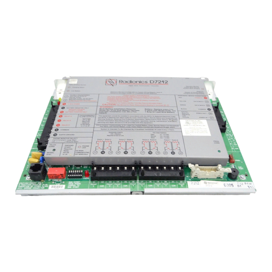
D8004 TRANSFORMER D122 DUAL ENCLOSURE. BATTERY HARNESS REQUIRED FOR NFP A APPLICATIONS. ARMING STATION D126 D1255 D126 D9131A PARALLEL REQUIRED BATTERY BATTERY 17 -05 823 - 0 02 UP TO EIGHT PRINTER 12V 7Ah SUPERVISED 12V 7Ah D1640 D7212 LEDs Off When Norma l INTERFACE O p er ati on M o nito r C harging Status... -
Page 61: Current Rating Chart For Standby Battery Calculations
Current Rating Chart for Standby Battery Calculations AC Power On AC Power Off In Alarm Normal Current Minimum Current Maximum Current Model Quantity Each Each Each Number Used Unit* Total Unit Total Unit Total D9412/D9112/ ______ x 1 = 350 x 1 = 350 x 1 = 500 D7412/D7212... -
Page 62: Standby Battery Requirements
Standby Battery Requirements Remote Station or Auxiliary Fire Alarm Household Burglary and Commercial 60 hours of standby plus 5 minutes of alarm operation required. See Remote Station or Auxiliary Burglary System Ampere-Hour Calculation Formula in the Four hours of standby battery capacity required. Standby Battery Calculation for NFPA 72 Fire Alarm Bank Safe and Vault Applications section. -
Page 63: Standby Battery Calculation For Nfpa 72 Fire Alarm Applications
Standby Battery Calculation for NFPA 72 Fire Alarm Applications Current Chart First Remote Station or Auxiliary Systems Ampere- See the Current Rating Chart for Standby Battery Hour Calculation Formula Calculations for totals B and C used in the formulas Total B Hours Total C Hours Contingency Total Ah... -
Page 64: Specifications
Continuous output is interrupted by Sensor Reset Two TelCo Lines or alarm verification depending on programming. Radionics D928 Dual Phone Line Module See the Relays section of the D9000/D7000 required for two phone line service. Supervision Series Program Entry Guide (74-07695-000) supplied by the panel. - Page 65 D8109 Fire Enclosure D720 Command Center (Area LED) D8108A Attack Resistant Enclosure D1640 16.5 VAC 40 VA Transformer Compatible Accessories See the Radionics Product Catalog for complete list. D5200 Programmer D122 Dual Battery Harness D5400 Remote Account Manager III D125B...
-
Page 66: Appendix: Point Address Chart
Appendix: Point Address Chart ZONEX 1, Points 9 to 127 (D9412/D9112) ZONEX 1, Points 9 to 75 (D7412/D7212) Place the labels on the base of the POPIT. Do not attach label to the POPIT cover. A number in the switch column indicates that switch is set to ON. Switch Switch Switch... -
Page 67: Bank 2, Points 129 - 247
• D8127 POPITs have dipswitches 1-6, whereas D9127 POPITs have dipswitches 0-6. ™ The Radionics logo is a registered trademark of Radionics © 1997 Radionics, Inc., Salinas, CA, USA. All rights reserved. Radionics, Inc., PO Box 80012, Salinas, California 93901-0012 www.PDF-Zoo.com...
Need help?
Do you have a question about the D9000 Series and is the answer not in the manual?
Questions and answers
radionics 000-80880 model wont stop beeping I removed the plate and that is the number on the inside of the wall mounted item.