Table of Contents
Advertisement
Quick Links
Item # 1006 615 785
Model # GFM30005B
USE AND CARE GUIDE
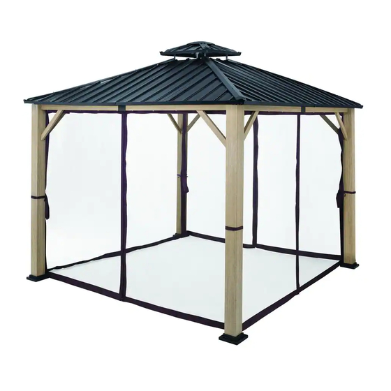
LORSTON 12 X 12 FT GAZEBO
Questions, problems, missing parts? Before returning to the store,
call Hampton Bay Customer Service
8 a.m. - 7 p.m., EST, Monday – Friday, 9 a.m. – 6 p.m., EST, Saturday
1-855-HD-HAMPTON
HAMPTONBAY.COM
THANK YOU
lly create
quality products designed to enhance your home. Visit us online to see our full line of products available for your home improv
ement needs.
Thank you for choosing Hampton Bay!
Advertisement
Table of Contents

Related Manuals for HAMPTON BAY LORSTON GFM30005B


Summary of Contents for HAMPTON BAY LORSTON GFM30005B
- Page 1 8 a.m. - 7 p.m., EST, Monday – Friday, 9 a.m. – 6 p.m., EST, Saturday 1-855-HD-HAMPTON HAMPTONBAY.COM THANK YOU lly create quality products designed to enhance your home. Visit us online to see our full line of products available for your home improv ement needs. Thank you for choosing Hampton Bay!
-
Page 2: Table Of Contents
Table of Contents Table of Contents........2 Pre-Assembly. -
Page 3: Warranty
Warranty 2 YEAR FRAME AND 2 YEAR FABRIC WARRANTY WHAT IS COVERED We warrant the frames to be free of manufacturing defects to the original purchaser for two years, and a two year warranty for the fabric. WHAT IS NOT COVERED It remains the customer’s responsibility for freight and packaging charges to and from our service center. -
Page 4: Package Contents
Pre-Assembly (continued) PACKAGE CONTENTS Part Description Part Description Quantity Quantity Post Border Tube Outer Metal Part Post Base Plate Top Frame Plug Post Base Cap Top Frame Tube Long Beam 1 Metal Plate 2 Long Beam 2 Metal Plate 3 Beam Decorator Metal Plate 4 Beam Lining... -
Page 5: Assembly
Assembly Attaching the Post Base Cap and the Post Base Plate to the Post Attach the post base cap (B1) and the post base plate (B) to the posts (A) using M6x15 Combination Bolts (AA). Repeat this step for the other three posts (A). Fully tighten the bolts using the hex wrench (OO). - Page 6 Assembly (continued) Attaching the Long Beam 1 and Long Beam 2 to the Beam Lining and the Beam Decorator Attach the long beam 1 (C) and long beam 2 (C1) to the beam lining (D1). Attach the long beam 1 (C) and long beam 2 (C1) to the beam decorator (D) using M6x75 Combination Bolts (EE) and M6 nuts (HH). Repeat this step for the other three long beams.
- Page 7 Assembly (continued) Attaching the Assembled Long Beam to the Post Attach the assembled long beam (C&C1) to the two posts (A) using M6X40 combination bolts (CC). Repeat this step for the other two posts (A). Fully tighten all the bolts at this step. HAMPTONBAY.COM Please contact 1-855-HD-HAMPTON...
- Page 8 Assembly (continued) Connecting the Assembled Long Beam to the Assembled Post Attach the assembled long beam (C&C1) to the assembled posts (A) using M6X40 combination bolts (CC) as shown below. Fully tighten all the bolts at this step.
- Page 9 Assembly (continued) Attaching the Support Bar to the Beam and the Post Attach the support bars (E) to the posts (A) using M6x15 combination bolts (AA). Attach the support bars (E) to the long beam1 (C) and long beam2 (C1) using M6x15 combination bolts (AA). Fully tighten all the bolts at this step.
- Page 10 Assembly (continued) Attaching the Corner Fitting to the Corner Incline Tube, Attaching the Middle Fitting to the Middle Incline Combination Set, Fixing the Stud to the Corner Incline Tube and the Middle Incline Combination Set Attach the corner tting (K) to the corner incline tube (L) using M6x15 combination bolt (AA). Fix the dia.7x41 stud (FF) to the corner incline tube (L).
- Page 11 Assembly (continued) Attaching the Corner Incline Tube to the Post and the Top Frame Tube Insert the top frame plug (O) to the corner incline tube (L) and the top frame tube (O1) as shown below. Fully tighten all the bolts at this step. HAMPTONBAY.COM Please contact 1-855-HD-HAMPTON...
- Page 12 Assembly (continued) Attaching the Middle Incline Combination Set to the Top Frame Tube and the Beam Insert the middle incline combination set (L1) into the top frame tube (O1) as shown Attach the middle incline combination set (L1) to the corner incline tube (L) using the M6x15 Combination bolt (AA). Attach the middle incline combination set (L1) to the beam decorator (D) using the M6 nuts (HH) and M6x75 Combination Bolts Fully tighten all the bolts at this step.
- Page 13 Assembly (continued) Inserting the Top Corner Incline Tube to the Bottom Plate, Attaching the Top Corner Incline Tube and the Top Border Tube to the Incline Outer Metal Part Insert the top corner incline tube (U) to the bottom plate (Y). Attach the top corner incline tube (U) and the top border tube (V) to the incline outer metal part (N) using the M6x15 combination bolt (AA) as shown below.
- Page 14 Assembly (continued) Attaching the Metal Plate 1 to the Top Border Tube Attach the metal plate 1 (W) to the top border tube (V) using the M6x15 combination bolts (AA). Fully tighten all the bolts at this step.
- Page 15 Assembly (continued) Attaching the Top Cover Plate and the Top Plate to the Metal Plate 1, Attaching the Top Plate and the Hook to the Bottom Plate Attach the top cover plate (X) to the metal plate 1 (W) using the M6x40 combination bolts (CC). Attach the top plate (Z) to the bottom plate (Y) using the M6x30 combination bolt (BB) and plastic washer (II).
- Page 16 Assembly (continued) Attaching the Top Corner Incline Tube to the Top Frame Plug Attach the top corner incline tube (U) to the top frame plug (O) using the M6x15 combination bolts (AA). Fully tighten all the bolts at this step.
- Page 17 Assembly (continued) Attaching the Border Tube to the Incline Tube Attach the border tube 1 (M) and border tube 2 (M1) to the corner incline tube (L) using the M6x15 combination bolts (AA). Attach the border tube 1 (M) and border tube 2 (M1) to the middle incline combination set (L1) using the M6x15 combination bolts (AA). Fully tighten all the bolts at this step.
- Page 18 Assembly (continued) Attaching the Metal Plate Attach the metal plate 8 (S) to the middle incline combination set (L1) using Dia.25 Plastic washer (JJ), M6 nut (HH) and nut cover (LL). Fully tighten all the bolts at this step.
- Page 19 Assembly (continued) Attaching the Metal Plate Attach the metal plate 7 (R1) and metal plate 6 (R) to the corner incline tube (L) using the M6x15 combination bolts (AA). Attach the metal plate 6 (R) and metal plate 8 (S) to the border tube 2 (M1) using the M6x30 combination bolts (BB). Attach the metal plate 7 (R1) and metal plate 8 (S) to the border tube 1 (M) using the M6x30 combination bolts (BB).
- Page 20 Assembly (continued) Attaching the Metal Plate Attach the cover plate (T) to the assembled frame using the Dia.16 Plastic washer (KK), M6 nut (HH) and nut cover (LL). Fully tighten all the bolts at this step. STEP 2 STEP 1...
- Page 21 Assembly (continued) Attaching the Metal Plate Attach the metal plate 4 (Q) and metal plate 5 (Q1) to the corner incline tube (L) using the M6x15 combination bolts (AA). Attach the metal plate 5 (Q1) and metal plate 7 (R1) to the border tube1 (M) using M6x30 combination bolts (BB). Attach the metal plate 4 (Q) and metal plate 5 (Q1) to the border tubes (M&M1) using the M6x15 combination bolts (AA).
- Page 22 Assembly (continued) Attaching the Metal Plate Attach the metal plate 2 (P) and metal plate 3 (P1) to the corner incline tube (L) using the M6x15 combination bolts (AA). Attach the metal plate 4 (Q) and metal plate 2 (P) to the border tube 2 (M1) using the M6x30 combination bolts (BB). Attach the metal plate 3 (P1) and metal plate 5 (Q1) to the border tube (M) using the M6x30 combination bolts (BB).
- Page 23 Assembly (continued) Inserting the Cover Plate Insert the cover plate 2 (T1) into the cover plate 1 (T) using Dia.16 plastic washer (KK), M6 nut (HH) and nut cover (LL). Fully tighten all the bolts at this step. HAMPTONBAY.COM Please contact 1-855-HD-HAMPTON for further assistance.
- Page 24 Assembly (continued) Attaching the Outer Metal Part Attach the incline outer metal part (N) and the border tube outer metal part (N1) to the assembled frame using the M6x15 combination bolts (AA) as shown below. Fully tighten all the bolts at this step. STEP 1 STEP 2...
- Page 25 Assembly (continued) Tightening the Bolts and Securing the Post to the Ground Once all of the bolts are in place, fully tighten all the bolts using wrench (NN) and hex wrench (OO). Secure the post (A) to the ground using ground spike (MM). HAMPTONBAY.COM Please contact 1-855-HD-HAMPTON...
- Page 26 Assembly (continued) Attaching the Fabric Rod to the Assembled Long Beam Insert fabric rod (F) into fabric rod cap (G),then attach to the assembled long beam (C&C1) using M6x40 bolts (DD). Once all of the bolts are in place, fully tighten all the bolts using the hex wrench (OO). C&C1...
- Page 27 Assembly (continued) Attaching the Split Rings and Netting Attach the split rings (H) to the fabric rods (F). Attach the netting (J) to the assembled gazebo using the split rings (H) as shown below. STEP 1 STEP 2 HAMPTONBAY.COM Please contact 1-855-HD-HAMPTON for further assistance.
- Page 28 Care Care and Cleaning For best results, clean the gazebo with a damp cloth and dry thoroughly. This will help prevent mildew by removing dirt particles that may accumulate. Do not clean with abrasive materials, bleach or solvents. Store the gazebo in a dry, sheltered place when not in use. Keep the gazebo away from fire, extreme heat, freezing conditions, and inclement weather as rain, hail, sleet, snow, or wind.
- Page 29 Questions, problems, missing parts? Before returning to the store, call Hampton Bay Customer Service. 8 a.m. - 7 p.m., EST, Monday - Friday, 9 a.m. - 6 p.m., EST, Saturday 1-855-HD-HAMPTON HAMPTONBAY.COM Retain this manual for future use.
Need help?
Do you have a question about the LORSTON GFM30005B and is the answer not in the manual?
Questions and answers