Table of Contents
Advertisement
Item #1003 516 705
Item # 1003 516 705
Model #GFM00471A
Model # GFM00471A
USE AND CARE GUIDE
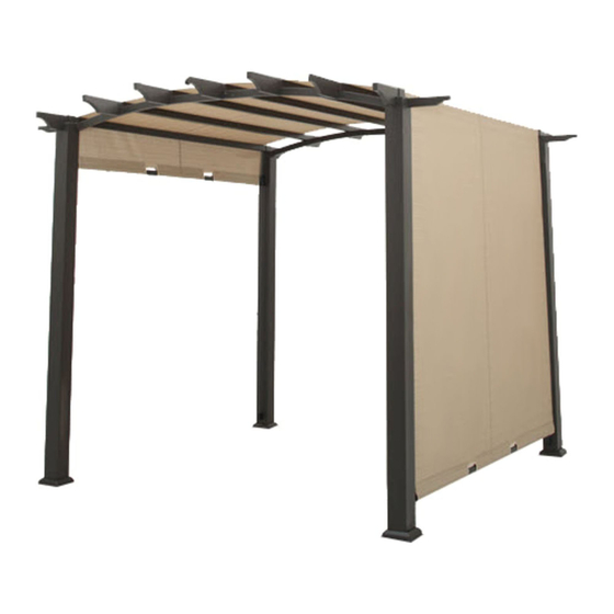
10x10 FT. PERGOLA
Questions, problems, missing parts? Before returning to the store,
call Hampton Bay Customer Service.
8 a.m. - 7 p.m., EST, Monday - Friday, 9 a.m. - 6 p.m., EST, Saturday
1-855-HD-HAMPTON
HAMPTONBAY.COM
THANK YOU
We appreciate the trust and conidence you have placed in Hampton Bay through the purchase of this pergola. We strive to continually create quality
products designed to enhance your home. Visit us online to see our full line of products available for your home improvement needs.
Thank you for choosing Hampton Bay!
Advertisement
Table of Contents

Related Manuals for HAMPTON BAY GFM00471A


Summary of Contents for HAMPTON BAY GFM00471A
- Page 1 THANK YOU We appreciate the trust and conidence you have placed in Hampton Bay through the purchase of this pergola. We strive to continually create quality products designed to enhance your home. Visit us online to see our full line of products available for your home improvement needs.
-
Page 2: Table Of Contents
Table of Contents Table of contents ..............2 Pre-assembly ................3 Safety Information ...............2 Planning assembly ..............3 Product Caution ................2 Hardware included ..............3 Safety Warnings ................2 Packaging contents ..............4 Warranty...................2 Assembly ................5 Care and Cleaning ...............17 What is covered ................2 What is not covered ..............2 Safety Information PRODUCT CAUTION This pergola was made for the explicit purpose of providing outdoor functions and is not to be used as a toy. -
Page 3: Pre-Assembly
Pre-Assembly PLANNING ASSEMBLY Read all instructions before assembly. To avoid damaging this product, assemble it on a soft, non-abrasive surface such as carpet or cardboard. NOTE: More than one person may be required to assemble this product. HARDWARE INCLUDED : Hardware not shown to actual size. NOTE Quantity Part... -
Page 4: Packaging Contents
Pre-Assembly (continued) PACKAGE CONTENTS Quantity Quantity Part Description Part Description End tip Right connector bar Left connector bar Inner tip Post base plate Top bar Top bar connector Post Tube cover Thin shade rod Plastic connector 1 Thick shade rod Plastic connector 2 Canopy... -
Page 5: Assembly
Assembly ATTACHING THE BRACKETS Insert the left connector bar (A2) into the right connector bar (A1), align the holes and secure the connector bars (A1 & A2) with M6x20 combination bolts (AA). NOTE : Fully tighten all bolts using the hex wrench (EE). HAMPTONBAY.COM Please contact 1-855-HD-HAMPTON for further assistance. - Page 6 Assembly (continued) INSERTING THE END TIPS Insert the end tips (G) into the top bar (B) and align the holes. Repeat this step for another top bar (B).
- Page 7 Assembly (continued) ATTACHING THE TWO TOP BARS TO THE CONNECTOR BARS Attach the two top bars (B) to the assembled left and right connector bars (A1 & A2) by using the top bar connectors (J). Secure the top bar connectors (J) with M6x20 combination bolts (AA) and M6x70 combination bolts (CC), as shown below. NOTE : Make sure the screw holes on the assembled left and right connector bars (A1 &...
- Page 8 Assembly (continued) INSERTING THE INNER TIPS Insert the inner tips (H) into the top bar (B) and align the holes. Repeat this step for the other four top bars (B).
- Page 9 Assembly (continued) ATTACHING THE TOP BARS TO THE CONNECTOR BARS Attach the top bars (B) to the assembled left and right connector bars (A1 & A2) using M6x70 combination bolts (CC), as shown below. A1&A2 HAMPTONBAY.COM Please contact 1-855-HD-HAMPTON for further assistance.
- Page 10 Assembly (continued) ATTACHING THE POST BASE PLATES TO THE POSTS Attach the post base plates (I) to the four posts (C) using M6x20 combination bolts (AA). NOTE : Fully tighten all bolts using the hex wrench (EE).
- Page 11 Assembly (continued) ATTACHING THE POSTS TO THE ASSEMBLED STRUCTURE Align the holes and attach the posts (C) to the assembled structure using M6x20 combination bolts (AA) and M6x70 combination bolts (CC). NOTE : : Suggest using two ladders to assemble this step. A1&A2 HAMPTONBAY.COM Please contact 1-855-HD-HAMPTON for further assistance.
- Page 12 Assembly (continued) ATTACHING THE POSTS TO THE ASSEMBLED STRUCTURE Align the holes and attach the other two posts (C) to the assembled structure using M6x20 combination bolts (AA) and M6x70 combination bolts (CC). Once all of the bolts are in place, fully tighten the bolts. NOTE : : Suggest using two ladders to assemble this step.
- Page 13 Assembly (continued) ATTACHING THE CANOPY Attach the canopy (F) to the assembled structure, as shown below. HAMPTONBAY.COM Please contact 1-855-HD-HAMPTON for further assistance.
- Page 14 Assembly (continued) ATTACHING THE THICK SHADE RODS Insert the thick shade rods (E) through the canopy (F), as shown below. Attach the plastic connector 1 (L1) and the plastic connector 2 (L2) to the right and the left side of the thick shade rod (E), repeat this step for another side.
- Page 15 Assembly (continued) ATTACHING THE THIN SHADE RODS Insert the thin shade rods (D) through the plastic connector 1 (L1) and plastic connector 2 (L2), as gure 1. Connect the tube covers (K) to the top of the thin shade rods (D), align the holes and secure the thin shade rods (D) using M6x55 combination bolts (BB), as gure 2.
- Page 16 Assembly (continued) INSTALLING THE GROUND SPIKES Insert the ground spikes (DD) through the post base plates (I) and into the ground.
-
Page 17: Care And Cleaning
Assembly (continued) COMPLETING THE ASSEMBLY Ensure all connections are secure before use. To adjust the length of the canopy (F), keep the plastic connectors 1 (L1) and the plastic connectors 2 (L2) in unlock position. The length of the canopy (F) cannot be adjusted when the plastic connectors 1 (L1) and the plastic connectors 2 (L2) in lock position. - Page 18 Questions, problems, missing parts? Before returning to the store, call Hampton Bay Customer Service. 8 a.m. - 7 p.m., EST, Monday - Friday, 9 a.m. - 6 p.m., EST, Saturday 1-855-HD-HAMPTON HAMPTONBAY.COM Retain this manual for future use.
Need help?
Do you have a question about the GFM00471A and is the answer not in the manual?
Questions and answers