Table of Contents
Advertisement
Quick Links
Advertisement
Table of Contents

Related Manuals for Liquid Controls LectroCount LCR 600


Summary of Contents for Liquid Controls LectroCount LCR 600
- Page 1 LectroCount LCR 600 E3708/E3709 Series...
-
Page 2: Table Of Contents
Safety Procedures ........................5 ESD Protection ..........................7 Specifications ..........................9 Safety Markings .......................... 12 Dimensions ..........................13 LectroCount LCR 600 Overview ....................15 Meter System Overview ......................17 Installation LectroCount Ground Strap Kit ....................24 Attach Ground Strap ........................26 Check for a Good Ground ...................... -
Page 3: Introduction
Introduction Introduction LectroCount LCR 600 ® E3708/E3709 Series This is the Installation and Parts Guide for the Liquid Controls LectroCount LCR 600 Register. -
Page 4: Publication Updates And Translations
Introduction Publication Updates and Translations The most current English versions of all Liquid Controls publications are available on our web site, www.lcmeter.com. It is the responsibility of the local distributor to provide the most current version of LC manuals, instructions, and specification sheets in the required language of the country, or the language of the end user to which the products are shipping. -
Page 5: Safety Procedures
Introduction Safety Procedures BE PREPARED · Before using this product, read and understand the instructions. · All work must be performed by qualified personnel trained in the proper application, installation, and maintenance of equipment and/or systems in accordance with all applicable codes and ordinances. - Page 6 Introduction Power, input, and output (I/O) wiring must be in accordance with the area classification for which it is used (Class I, Div 2). For North America, installations must be per the U. S. National Electrical Code, NFPA 70, or the Canadian Electrical Code in order to maintain Class I, Division 2 ratings.
-
Page 7: Esd Protection
LectroCount register from any point of the truck’s electrical system, such as the cabling from the LectroCount register to the cab or the Epson printer. Liquid Controls Grounding Kits To protect electronic components from ESD, all LectroCount truck intallations must include the installation of the LectroCount Ground Strap Kit (PN 82185) and the Epson Printer Ground Wire Kit (PN 82184). - Page 8 Introduction Alternate grounding method Connect the green ground screw (inside the LectroCount housing in the upper right corner) to a known good ground (less than 1 ohm). Use a 12 gauge or larger stranded wire. FIXED INSTALLATIONS LectroCount housings directly mounted to the meter are attached to the earth ground through the meter via the tank and the tank piping ,which is grounded by the electrical system grounding rods.
-
Page 9: Specifications
Introduction Specifications Mechanical Materials of Construction · Aluminum Alloy ADC12 · Powder Coat – Corro-Coat PE 74-141 Polyester Weight · 8.75 lbs (4 kg) Display Elements · Liquid crystal display · 320 X 240 pixels Cable Entry · ½? NPT (5) ·... - Page 10 Introduction Scale Pulse Output · Current sinking capability: 150 mA Electrical Protection · 5 A fuse on power cable Input/Output Specifications Communications · RS-232: EIA-232E standard · RS-485: SAE J1708 standard Auxiliary 1 Output · Current sinking capability – 1 A Auxiliary 2 Output ·...
- Page 11 Introduction · Current – 0.5 Amp maximum RTD Temperature Probe · 4 wire platinum sensor · 100 Ω resistance at 0 C · 138.5 Ω resistance at 100 C Printer (Epson Model 295) · Voltage – 24 VDC · Current – 0.8 Amp maximum ·...
-
Page 12: Safety Markings
Introduction Safety Markings The equipment is Listed by UL to applicable US and Canadian standards for use in hazardous locations under Liquid Controls file E180172. Class I Potentially Explosive Gas/Vapor Atmospheres. Division 2 Gases and vapor are not normally present in an explosive concentration but may accidentally exist during abnormal operations. -
Page 13: Dimensions
Introduction Dimensions... - Page 14 Introduction...
-
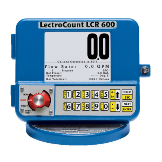
Page 15: Lectrocount Lcr 600 Overview
The LCR 600 is capable of interfacing in RS-232 and RS- 485 communication protocols. HOUSING The LectroCount LCR 600 housing and base are aluminum die cast and powder coated. The hinge door design provides easy access to the internal connections and a Weights and Measures sealable fastener opposite the hinges. - Page 16 Introduction SELECTOR SWITCH The selector switch controls basic stop, run, print, and shift print delivery functions. To perform calibration functions, the cover plate must be removed and the selector switch turned to the six o’clock position. BASIC FUNCTIONS The principle functions of the LectroCount registers include: ·...
-
Page 17: Meter System Overview
LectroCount LCR 600 (in LPG applications, they are often plumbed to a 3-way solenoid which is wired to the LectroCount LCR 600). Optical air eliminators use an optical sensor to monitor liquid levels and a solenoid-actuated valve to turn the vapor vent on and off. The optical sensor and the solenoid valve are connected to the LectroCount LCR 600 by separate data cables. - Page 18 By slowing the flow rate, valves can lessen the hydraulic shock incurred by the meter system upon shut off and provide accurate preset deliveries. Many valves use solenoid-operated valves that require a hard-wired data connection to the LectroCount LCR 600. See manuals M400-11 and M400-40.
- Page 19 XL LED REMOTE DISPLAY The XL LED Remote Display’s six 2¼” high digits, each consisting of 18 red LED lights, are discernible from up to 250 feet away. Hard wire data communication with the LectroCount LCR 600 is required. See manual EM300-55.
- Page 20 (pressure drop) across a full flow fuel monitor/water coalescer. The highest differential pressure reached during the custody transfer will then be printed on the ticket. Using interlocks, the LectroCount LCR 600 can shut down a custody transfer if the differential pressure meets a preprogrammed differential pressure shutdown value.
- Page 21 LectroCount LCR 600. See manuals EM200-10 and EM200-11. EZCOMMAND EZCommand is Windows®-based interface that saves and distributes LectroCount LCR 600 settings and updates. EZCommand can be loaded onto a laptop. Using a lap pad adapter (PN 81514) and a printer extension cable (PN 71815), the lap top can be quickly connected to upload settings and updates in the field.
-
Page 22: Installation
Installation Installation If the LectroCount LCR 600 was ordered as part of a meter system, it will arrive mounted on the meter and prewired to the ETVC probe, air eliminator, and valve. Installation overview for LCR 600 ordered with meter system: 1. - Page 23 Installation This manual explains and details the mechanical installation of the LectroCount LCR 600 and the temperature probe as well as the electrical and data installation of all components that connect to the LCR 600. For additional installation information, refer to the manuals of the other components. All manuals are available at www.lcmeter.com.
-
Page 24: Lectrocount Ground Strap Kit
Installation LectroCount Ground Strap Kit All seat cushions are grounded in a similar manner. The illustrations below detail the following instructions for grounding three typical types of truck seats. ESD Precaution Install the LectroCount Ground Strap Kit before installing the LectroCount register. Follow these steps to ground a truck seat: 1. - Page 25 Installation is attached to the wood. There must be good contact between the seat fabric and ground strap lug. 5. Use the wire ties provided with the kit and tie off the strap so that it doesn’t interfere with the movement of the seat and is clear of traffic areas in the cab. 6.
-
Page 26: Attach Ground Strap
Installation Attach Ground Strap Typical Adjustable Truck Seats The diagrams below demonstrate how to attach the ground strap to typical truck seats. Air Cushion Seat - Adjustable for Height (Bostrom 914 Series, National 2000 Series, or equivalent) Air Cushion Seat - Adjustable for Height (Dura-Form or equivalent) - Page 27 Installation Bench Seats - Adjustable for Distance to the Steering Wheel (Manufacturer Standard or equivalent)
-
Page 28: Check For A Good Ground
Installation Check for a Good Ground After installing the ground kits, use a multimeter to confirm that the seat and printer are both grounded properly. Follow these steps to verify a good ground connection: 1. Turn OFF all accessories, including the dome light, to prevent other currents from distorting the reading. -
Page 29: Mounting Overview
Mounting Overview Mounting Overview Typically, the LectroCount LCR 600 is mounted directly onto a flow meter; however, some fixed installations require the register be mounted away from the meter. If the meter is equipped with an external POD pulser, the LCR 600 can be mounted up to 1000 wire feet (304 meters) away from the meter (actual distance depends on pulser specifications and wire type). - Page 30 Installation WARNING Relieving Internal Pressure All internal pressure must be relieved to zero pressure before disassembly or inspection of the strainer, vapor eliminator, any valves in the system, the packing gland, and the front or rear covers. Serious injury or death from fire or explosion could result in performing maintenance on an improperly depressurized and evacuated system.
- Page 31 Installation 7. As product is bleeding from the differential valve, slowly reopen and close the valve/nozzle on the discharge line. Repeat this step until the product stops draining from the differential valve and discharge line valve/nozzle. 8. Leave the discharge line valve/nozzle open while working on the system.
-
Page 32: Mounting The Lcr 600
Mounting the LCR 600 Mounting Bolt Pattern The LectroCount LCR 600 base casting contains eight bolt holes in an industry standard bolt pattern. The holes are ½" deep and take ¼"-20 screws. If the installation necessitates that you fabricate a bracket, refer to the drawing to the right. - Page 33 Installation Mount the LectroCount LCR 600 Follow these steps: 1. Place the end of the shaft adapter on the pulser drive shaft located on the bottom of the register. 2. Place the cotter pin through the hole, and bend open the ends of the cotter pin.
- Page 34 4. Remove the bellows from the front of the meter. 5. Remove the compensator. Mount the LectroCount LCR 600 Follow these steps: 1. Install the drive fork and extension piece (pictured below) on the pulser drive shaft located on the bottom of the LCR 600.
- Page 35 Apply Anti-seize Apply anti-seize to all bolt threads to ensure easy removal at a later date. Mount the LectroCount LCR 600 on previously temperature compensated Neptune meters 1. Place the shaft adapter on the pulser drive shaft under the LCR 600.
- Page 36 Installation Installation kits 82641 (E-26 series) & 82642 (E-36 series) are specifically designed for previously temperature compensated Neptune meters.
-
Page 37: Routing Lcd 600 Data And Power Cables
Installation Routing LCD 600 Data and Power Cables Data and Power Cable The LCR 600 shipment typically includes a gray 40-foot power cable and a 40-foot black data cable, prewired to terminal blocks on the LCR 600 CPU board. On typical truck installations, the cables must be routed from the back of the truck–where the LCR 600 is installed–to the front of the truck, where the accessory panel is and the printer is typically installed. - Page 38 Installation · If the cables are shortened, ensure that you use the proper tool for stripping off the insulation on the cables. · Make sure cables are connected to the proper terminal. Guidelines for routing the data and power cables inside the cab ·...
-
Page 39: Electronic Temperature Volume Compensation
Installation Electronic Temperature Volume Compensation Electronic Temperature Volume Compensation (ETVC) Installation When ordered as part of a meter system with a LCR 600, the ETVC kit is bolted onto the strainer and wired to the LCR 600 at the factory. ETVC kits can also be ordered and retrofit onto meter systems already in service. - Page 40 Installation To install the ETVC kit: Depressurize the meter completely. See the Warnings in Mounting Overview Remove the old strainer cover. Clean the strainer basket and replace it into the housing. Lightly coat the new cover gasket (included with the ETVC kit) with lubricant. DO NOT use the included copper grease.
- Page 41 Installation Coat the entire probe length with the copper grease provided. Insert and recoat the probe 2 or 3 times to provide a uniform coating inside the Thermowell and to ensure proper heat transfer from the liquid to the probe. Connect the assembled Thermowell to the fitting in the middle of the strainer cover.
- Page 42 Installation Disconnect Power Disconnect the power before working on the CPU board.
-
Page 43: Valves
These solenoid-operated valves must be wired to the LCR 600 CPU board during installation. Liquid Controls offers single-stage and two-stage electronic valves. Single stage valves have one solenoid valve (S1) and two positions—an open position and a closed position. Two-stage valves have two solenoid valves (S1 &... - Page 44 The 3-way solenoid-operated valve—mounted directly to the top center port on the back of the LectroCount LCR 600—serves as a S1 solenoid-operated valve. The 3-way solenoid-operated valve is located at the meeting point of two pipes from the vapor eliminator (one for eliminated vapor and one leading to the spit tank) and one pipe to the top of the block valve.
- Page 45 Installation Two-Stage Valves The three most common Liquid Controls meter systems with two stage valves are: · a block valve with a S1 and a S2 solenoid-operated valve fitted onto external piping (A2848-11) · a block valve with a S2 solenoid-operated valve (A2859-11) and a 3-way solenoid on the LCR 600 ·...
- Page 46 A two- stage valve with a S2 solenoid-operated valve and a 3-way solenoid valve attached to the back of the LectroCount LCR 600. The 3-way solenoid-operated valve is located at the meeting point of two pipes from the vapor eliminator (one for eliminated vapor and one leading to the spit tank) and one pipe to the top of the block valve.
- Page 47 Valve Installation If you install the valve yourself, refer to the valve installation and operation manual for mechanical installation. Instructions for wiring Liquid Controls valves to the LCR 600 can be found below. Materials needed for wiring valves These materials are necessary, but are not supplied with the valve: ·...
- Page 48 Installation Earth Grounds for Solenoid Valves The Earth grounds for Terminals 16 & 19 are optional. The solenoid operated valves are grounded through the component they are mounted on. To wire a single stage valves for presetting: 1. Wire the S1 solenoid, as instructed above. 2.
- Page 49 Liquid Controls valves use cable assembly 81859, which has 2 cables. Valves with 110VA C Solenoids In order for the LectroCount LCR 600 to control valves with solenoids on 110 VAC circuits, you must install a relay switch on the positive leg of the solenoid’s circuit. Relay switch specifications: ·...
- Page 50 Installation Materials needed for wiring valves with 110 VAC solenoids These materials are necessary, but are not supplied with the valve: · SPST relay switch (1 per solenoid) · 20 AWG stranded wire (2 per solenoid) · Weatherproof flexible conduit, ½" diameter and ½" NPT conduit connectors or cable glands ·...
-
Page 51: Optical Air And Vapor Eliminators
Installation Optical Air and Vapor Eliminators Optical Air and Vapor Eliminator Installations When ordered as part of a meter system with a LCR 600, the Liquid Control optical air and vapor eliminators are bolted onto the strainer and wired to the LCR 600 at the factory. Optical air and vapor eliminators can also be ordered separately and installed onto meter systems already in service. - Page 52 LCR 600 port. 3. Run the weatherproof conduit between the S3 solenoid operated valve and the LCR 600 housing. Pull the wires through the ports, and tighten the connectors. Liquid Controls recommends running the optical sensor wire through weatherproof conduit as well.
- Page 53 Installation 4. Connect the three 20 AWG wires to the S3 solenoid operated valve terminals and to terminals 52 and 53 on the J15 terminal block of the LCR 600 CPU board. 5. Connect the optical sensor wires to terminals 54, 55, and 56 on the J15 terminal block of the LCR 600 CPU board.
- Page 54 Installation...
-
Page 55: Pulse Output Device
Installation Pulse Output Device Pulse Output Device (POD) Installation When ordered as part of a meter system with a LCR 600, Liquid Control’s Pulse Output Device (POD) is installed onto the meter and wired to the LCR 600 at the factory. The POD can also be ordered separately and installed onto meter systems already in service. - Page 56 Installation To wire a POD to the LCR 600: 1. Attach cable glands and/or conduit connectors to the POD and the LCR 600 port(s). 2. Thread the wires through a piece of weatherproof conduit cut-to-length from the POD port to a LCR 600 port.
- Page 57 Installation To wire a single channel pulse output to the LCR 600: 1. Slide the jumper over pins 2 & 3 (counting down from the top) of J17. The jumper fits over the pins and under the plastic casing. 2. Wire the single channel pulser to the J8 terminal of the 81920 CPU board. Schematic on the right shows wiring to a Sponsler SP714.
-
Page 58: Differential Pressure Transducer
Installation Differential Pressure Transducer Differential Pressure (∆P) Transducer Installation When ordered as part of a meter system with a LCR 600, Liquid Control’s ∆P transducer is wired to the LCR 600 at the factory. The ∆P transducer can also be ordered separately and installed onto a meter system already in service. - Page 59 Installation When removing the J1 or J16 terminal from the 81944 board, hold down the right end of the main CPU board to prevent flexing. To wire ∆P Transducer to the LCR 600: Unplug the J1, J2, and J3 terminal blocks from the LCR 600 CPU board. Leave the wires in the terminals.
- Page 60 Installation 10. Run the red jumper wire (provided with the ∆P transducer kit) from the J8 terminal 32 to J16 terminal 59 (+5 V). 11. Route a two-wire cable from the shutdown control device through a cable gland in a port on the back of the LCR 600.
- Page 61 Installation...
-
Page 62: Remote Display
Installation Remote Display LectroCount Remote Display - Auxiliary Outputs 4 & 5 Auxiliary outputs 4 and 5 are typically used for the 2¼" E1610 Large Remote Display, but they can also be used with other types of displays. Signals from these outputs duplicate the volume data sent to the LCR 600 display. - Page 63 Installation...
-
Page 64: Auxiliary Outputs
Installation Auxiliary Outputs Auxiliary Outputs 4 & 5 (LectroCount Remote Display) Auxiliary outputs 4 & 5 are typically used for the LectroCount Remote Display, but they can also be used for other types of displays. Signals from these outputs duplicate the volume data sent to the LCR 600 display. - Page 65 (for compensated deliveries). This output is a real time 50/50 duty cycle representing the least significant digit of the LCR 600 totalizers. Auxiliary Output Settings To select the Auxiliary Output settings, refer to the LectroCount LCR 600 Setup and Operation manual.
-
Page 66: Printers
Printers Printer Installation (J1 RS-232) A Liquid Controls meter system with a LCR 600 typically includes an Epson slip printer or roll printer. The installation is the same for either printer. An LCR 600 is typically shipped with a black-sheathed data cable prewired to terminals J1 and J3 on the LCR 600 CPU board. - Page 67 Installation Routing Data Cables See the instructions on Routing LCD 600 Data and Power Cables for routing the data cable from the back of the truck to the cab. Disconnect Power Disconnect the power before working on the CPU board. RS-232 Communication To communicate by means of genuine RS-232 protocol, the +VP Red wire must be connected to the J3 terminal block at terminal 47 (not 46).
- Page 68 4. Place the other end terminal of the ground wire over the ground screw and return the screw to its original place. 5. Check the strap for a good ground connection (see page 13). Additional Terminal that are not purchased from Liquid Controls.
-
Page 69: Data Communications
Installation Data Communications RS-232 and RS-485 Communications The LCR 600 is capable of interfacing with RS-232 and R-S485 communication protocols. Data connections for these protocols are made at the J2 and J3 terminal blocks. A jumper, located on the left side of the CPU board, can also affect communication protocol;... -
Page 70: Power Supply
11 Volts. · Inspect the electrical equipment on the vehicle to ensure proper installation and operation. · Determine whether the vehicle is grounded positively or negatively. Consult Liquid Controls if the vehicle has a positive ground. · Ensure that any radio antennas are installed according to manufacturer specifications to prevent RF interference. - Page 71 Installation Epson Printer Power Power must also be supplied to the Epson printer. For supplying power to the printer, a 15-foot cable with a 12/24VDC converter (825001) is also available. The red wire of this cable must be spliced into the red wire in the gray power cable on the LCR 600 side of the 5 Amp fuse.
- Page 72 Installation Epson Printer Power Connections LectroCount LCR 600 Power Connections...
-
Page 73: Finalize The Installation
Finalize the Installation IMPORTANT: Before Sealing the LCR 600 After correctly powering up the LCR 600, continue on to the LectroCount LCR 600 Setup and Operation manual to setup the LCR 600 for operation. We recommend that you setup and test the LCR 600 before closing and sealing the unit. - Page 74 Sealing the LCR 600 is the responsibility of the installer. Weights & Measures Seals To detect possible intrusions into Weights & Measures approved calibrations on a LectroCount LCR 600, fillister holes have been drilled into the switchplate screw and the latch. To seal according to Weights &...
-
Page 75: Bill Of Materials-External Components
Installation Bill of Materials–External Components... -
Page 76: Internal Components
Installation Internal Components... -
Page 77: Bill Of Materials - Cpu Boards
Installation Bill of Materials - CPU Boards 81920 CPU Board Do NOT Try to Remove J2 The J2 terminal block is permanently attached to the CPU board. Optional Items Description Part Number Lap Pad Adapter 81514 Printer Extension Cable 71237 Flash Cable 81885... -
Page 78: Lc Offices Worldwide
LC Offices Worldwide LC Offices Worldwide Liquid Controls 105 Albrecht Drive Lake Bluff, IL 60044 (847) 295-1050 Liquid Controls Europe/SAMPI Via Amerigo Vespucci 1 55011 Altopascio (Lucca), Italy +39 0583 24751 IDEX Fluid and Metering Pvt. Ltd. Survey No. 256, Alindra Savli GIDC, Manjusar Dist.
Need help?
Do you have a question about the LectroCount LCR 600 and is the answer not in the manual?
Questions and answers