
Related Manuals for Liquid Controls MS Series


Summary of Contents for Liquid Controls MS Series
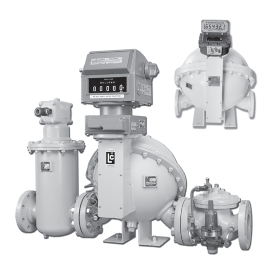
- Page 1 Installation & Parts Manual MS-Series Spherical Two-Case Meters Installation: M100-20 www.lcmeter.com...
-
Page 2: Table Of Contents
Parts Breakdown ..........36-39 Publication Updates and Translations The most current English versions of all Liquid Controls publications are available on our website, www.lcmeter.com. It is the responsibility of the Local Distributor to provide the most current version of LC Manuals, Instructions, and Specification Sheets in the required language of the country, or the language of the end user to which the products are shipping . -
Page 3: Safety Precautions
Evacuate the area and notify the fire department. present when using the Liquid Controls Meter on LPG and other products. The reading of these warnings and In the event of a small, contained gas leak: the avoidance of such hazards is strictly in the hands of 1. -
Page 4: How Lc Meters Work
Liquid Controls meters are made of a variety of materials At any position in the cycle, the meter body, the blocking to suit a variety of products. Because of our no-wear... -
Page 5: Owner's Information Packet
Owner’s Information Packet Is all the documentation included with the meter? LC Record the meter serial number in the space provided meters come in many variations. The information sent on Page 2 of this manual. This page also provides a depends on the accessories ordered with the meter. -
Page 6: Installation Requirements
Never leave any of call the Service Department at Liquid Controls. the pipes hanging. • Install the meter and accessories in conformance with •... -
Page 7: System Design Considerations
There is one batch leading vertically to the loading arm. The meter is controller for each metering position. equipped with a dual channel, quadrature pulse MS Series Meter Strainer/Air Eliminator Outlet Side Isolation Valve... - Page 8 System Design Considerations Design For Calibration Field calibration of meters is essential. Calibration conducted during meter production is to confirm the meter is capable of attaining the required accuracy/linearity and repeatability. Typically, the meter characteristics are: Mechanical Registration • Repeatability: Capable of .02% or better at any flow rate over entire range •...
- Page 9 System Design Considerations Design for Standard Mounting Arrangements (straight through flow) Regardless of meter mounting configuration, accessories such as the air/vapor eliminator must always be mounted in a vertical orientation to permit proper operation of the float-actuated apparatus. Design for Special Mounting Arrangements Special flange arrangements are available as shown.
- Page 10 System Design Considerations Design for Thermal Shock or Commissioning Expansion Once the metering system is installed, it is ready for commissioning. Filling the system the first time requires Temperature considerations in system design should not care and time. Ensure that the isolation valve on the be ignored.
-
Page 11: Operation Requirements
Operation Requirements The meter must remain full of product at all times. Provide a means of conveniently diverting liquid for An easy way to accomplish this is to put the meter calibration purposes. assembly in the line below the piping center-line (a sump position). -
Page 12: Meter Start Up And Operation
Electronic Registration ® Liquid Controls’ family of LectroCount electronic registers provide near-perfect metering accuracy over a full range of flow rates and deliver enhanced functions including: automated data collection (i.e., date, time, product, delivery quantity and more), on-site ticket generation, meter linearization, electronic temperature volume compensation, real-time communication capabilities (RF, GPS, CDPD), improved security and more. -
Page 13: Reversing The Meter Registration
Reversing the Meter Registration The direction of flow is specified by the customer when Adjuster drive the meter is ordered. The standard direction of flow is gear engaged from left to right when facing the front of the meter. A red, pressure sensitive label indicating the inlet is affixed to from the top. -
Page 14: Setting The Standard Adjuster
Setting the Standard Adjuster Note: These instructions apply to meters equipped with mechanical output accessories only. If the meter is equipped with an electrical output assembly, refer to the accessory manual, such as the Pulser Manual or LectroCount Manual in your Owner’s Information Packet. 1. -
Page 15: Meter Maintenance
Meter Maintenance ! ! ! ! ! WARNING RELIEVING INTERNAL PRESSURE All internal pressure must be relieved to zero before disassembly or inspection of the strainers, air eliminators, valves, the pulse output device (POD), or the front and rear covers. Serious injury or death from fire or explosion could result from maintenance of an improperly depressurized and evacuated system. - Page 16 Torque specifications. All fasteners such as screws and resolved. Contact your full-service distributor or the bolts should be torqued to proper specification. See the Service Department at Liquid Controls for assistance if “Torque Chart” on Page 31 of this manual. this occurs.
-
Page 17: Servicing The Drive Components
Servicing the Drive Components Removing the Dust Cover 1. Cut the dust cover seal wire (if present) with a side cutters. Remove the dust cover screws with a flat blade screwdriver. Remove the dust cover. NOTE: See Relieving Internal Pressure and Weights &... - Page 18 Servicing the Drive Components Removing the Adjuster and Adjuster Drive Assembly (Continued) 4. Use a flat blade screwdriver to remove the two screws of the upper retaining spring. 5. Use a flat blade screwdriver to remove the two screws of the lower retaining spring. 6.
-
Page 19: Servicing The Packing Gland
Servicing the Drive Components Removing the Adjuster and Adjuster Drive Assembly (Continued) 7. Remove the Adjuster assembly by removing the single screw holding it in place. The adjuster can then be rotated clockwise and removed from below. Removing the Packing Gland ! ! ! ! ! WARNING All internal pressures must be relieved before disassembly of the meter, strainer, vapor eliminator, any valves in the system, the pulse output device, or the front and rear covers. -
Page 20: Packing Gland Components
Servicing the Drive Components Standard Packing Gland LPG Packing Gland Housing Housing Drive Blade Drive Blade Bushing Bushing Shaft Shaft Retaining Clip Retaining Clip “U” Cup “U” Cup Rulon Thrust Washer Stainless Steel Washer Stainless Steel Thrust Washer O-Ring Nylon Washer Retaining Plate O-Ring Retaining Plate Screws (2) -
Page 21: Disassembling The Meter
Disassembling the Meter Tools: Standard screwdrivers (2) Spare displacement rotor gear Torque Chart Bearing plate wrench Wrench & Socket Size Chart Plastic or rubber mallet Counter bracket wrench or socket Emery cloth Drain plug wrench Wire brush Cover socket or open end/box end wrench (See Pages 31 &... -
Page 22: Removing Rotor Gears
Disassembling the Meter 3. When all the screws and bolts have been removed, remove the weldment cover. This exposes the inside of the weldment assembly and provides access to the meter assembly. The meter assembly is held in place by 4 bolts on the inlet side of the meter. This can be either side of the meter depending on the direction of flow. - Page 23 Disassembling the Meter 6. Keeping the spare displacement gear between the right rotor gear and blocking gear, use the allen wrench to loosen the screw of the right rotor gear assembly. 7. To loosen the screw of the blocking rotor gear, move the spare displacement rotor gear to between the left rotor gear and the blocking rotor gear to prevent the gears from moving.
-
Page 24: Removing The Bearing Plate & Rotors
Disassembling the Meter Removing the Rotor Gears 8. Using one or two flat blade screwdrivers, gently pry the gear off its rotor tapered end. Do this for each of the gears. As the rotor gear comes off, remove the key (1) from the rotor keyway (2). -
Page 25: Removing Meter Housing Assembly
Disassembling the Meter 10. When all the bolts are removed, insert a screwdriver into each of the two notches near the dowel pins. Be careful not to mar any of the surfaces. Gently pry the front bearing plate off the dowel pins. Remove the front bearing plate and rotor assemblies by pulling a rotor straight out from the housing. -
Page 26: Universal Joint Assembly
Disassembling the Meter Universal Joint Assembly 12. The Universal Joint is an extension used to connect the blocking rotor of the meter to the packing gland. When the blocking rotor rotates, the Universal Joint causes the packing gland to rotate which drives the register. -
Page 27: Reassembling The Meter
NOTE: The principles of meter disassembly and Cover socket or open end/box end wrench Spare displacement rotor gear or shop rag reassembly are the same for all Liquid Controls meters. Although your meter may look slightly different than those Rotor gear wrench or socket pictured, the steps are the same, except as noted. - Page 28 Reassembling the Meter 3. Install the two displacement rotors. Insert the non- tapered ends into the housing. Place each rotor into its respective bore on the bearing plate. 4. Install the bearing plate cover over the three tapered ends and fasten it with the bearing plate screws. Use the bearing plate wrench.
-
Page 29: Rotor Gear Timing
Reassembling the Meter Rotor Gear Timing 6. Slide the blocking rotor gear on its tapered rotor end. Slide the right displacement rotor gear on its tapered rotor end so that the timing marks line up between the two gears. HINT: Before placing the right displacement rotor gear on its end, hold the right rotor gear in position. -
Page 30: Reassembling Weldment Assembly
Reassembling the Meter Reassembling the Weldment Assembly 12. Install a new O-Ring in the groove around the weldment base assembly if required. 13. Position the weldment cover on top of the weldment base so that the cover vent plug is on top. Install the screws around the rim of the weldment cover. -
Page 31: Bolt Tightening Sequence
Wrench and Socket Size Chart Bolt Tightening Sequence When placing the weldment cover on the weldment base, it is important that the bolts are tightened in a sequence which reduces the risk of leaking when the system is put back in service. The number of bolts will vary depending on the size of the meter. -
Page 32: Fastener And Torque Chart
Fastener and Torque Chart FASTENERS USED Meter Element Weldment Assembly Meter Dust Counter Bearing Rotor Element Cover Drain Weldment Model Cover Bracket Plate Gear Mounting Vent Plug Cover Screws Screws Screws Screws Bolts Plug (6) #10-24 x .38 (4) .312-18x1 (10) .250-20x.75 (3) #10-24x.625 (4) .312-18x.75... -
Page 33: Identification Of Bolt Grades
Troubleshooting Identification of Bolt Grades Grade 0, 1, & 2 Grade 6 (No Markings) 4 radial dashes, 90º apart Grade 3 Grade 7 2 radial dashes, 180º apart 5 radial dashes, 72º apart Grade 5 Grade 8 3 radial dashes, 120º apart 6 radial dashes, 60º... -
Page 34: Troubleshooting
Troubleshooting Problem: Product flows through the meter but the register does not operate. Probable Cause: 1. Check the packing gland and gear train. 2. If all meter parts are moving, the problem is in the register. Faulty registers should be checked and repaired by a trained technician. -
Page 35: How To Order Replacement Parts
How to Order Replacement Parts 1. Refer to the exploded drawings of the meter on Pages 36-39. Find the four digit item number for the part you want to order. 2. Find the computer printout titled Bill of Materials that has been inserted in the red Owner’s Information Packet. -
Page 36: Parts Breakdown
Illustrated Parts Breakdown Adjuster Housing Assembly NOTE: Numbers shown are ITEM numbers, not Part Numbers. Refer to the Bill of Materials supplied in the red Owner’s Information Packet to locate the PART NUMBER associated with these ITEM NUMBERS. - Page 37 Illustrated Parts Breakdown Weldment Assembly NOTE: Numbers shown are ITEM numbers, not Part Numbers. Refer to the Bill of Materials supplied in the red Owner’s Information Packet to locate the PART NUMBER associated with these ITEM NUMBERS.
- Page 38 Illustrated Parts Breakdown Meter Element Assembly NOTE: Numbers shown are ITEM numbers, not Part Numbers. Refer to the Bill of Materials supplied in the red Owner’s Information Packet to locate the PART NUMBER associated with these ITEM NUMBERS.
- Page 39 Illustrated Parts Breakdown Complete Assembly NOTE: Numbers shown are ITEM numbers, not Part Numbers. Refer to the Bill of Materials supplied in the red Owner’s Information Packet to locate the PART NUMBER associated with these ITEM NUMBERS.
- Page 40 A Unit of IDEX Corporation 105 Albrecht Drive Lake Bluff, IL 60044-2242 1.800.458.5262 • 847.295.1050 © 2006 Liquid Controls Fax: 847.295.1057 Pub. No. 500318 www.lcmeter.com (4/13)
Need help?
Do you have a question about the MS Series and is the answer not in the manual?
Questions and answers