
Related Manuals for Liquid Controls LectroCount LCR-II E3655 Series


Summary of Contents for Liquid Controls LectroCount LCR-II E3655 Series
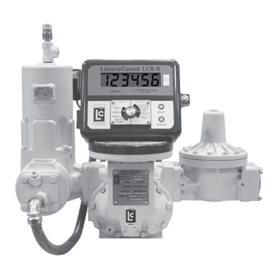
- Page 1 LectroCount LCR-II ® Installation E3655/E3656 Series Liquid ControLs Group An IDEX Fluid & Metering Business Operation: EM150-20...
-
Page 2: Table Of Contents
Publication Updates and Translations The most current English versions of all Liquid Controls publications are available on our web site, www.lcmeter.com. It is the responsibility of the local distributor to provide the most current version of LC manuals, instructions, and specification sheets in the required language of the country, or the language of the end user to which the products are shipping. -
Page 3: Safety Procedures
safeTy ProCedUres be Prepared ! WarnInG • Before using this product, read and understand the instructions. • All work must be performed by qualified personnel trained in the proper application, installation, and maintenance of equipment and/or systems in accordance with all applicable codes and ordinances. •... -
Page 4: Esd Protection
LectroCount register to the cab or the Epson printer. liquid Controls’ Grounding Kits To protect electronic components from ESD, all LectroCount truck intallations must include the installation of the LectroCount Ground Strap Kit (PN 82185) and the Epson Printer Ground Wire Kit (PN 82184). -
Page 5: Specifications
sPeCIfICaTIons Mechanical Input/output Materials of Construction Communications • Aluminum Alloy ADC12 • RS-232: EIA-232E standard • Powder Coat: Corro-Coat PE 74-141 Polyester • RS-485: SAE J1708 standard Weight Auxiliary 1 Output • 8.4 lbs (3.8 kg) sinking capability: 1 A Current Display Elements Auxiliary 2 Output... -
Page 6: Dimensions
dIMensIons ront 15" 9.94" 5.19" L e ct ro C o u nt L C R -I I 10.5" 8.04" 70º Ø 7.5" 13"... -
Page 7: Lectrocount Lcr-Ii Overview
Smith positive displacement meters). This pulse The principle functions of the LectroCount registers output can also come from a Liquid Controls external include: POD pulser or another pulse generator. In addition to the pulse input, the LCR-II is equipped with an input for •... -
Page 8: Meter System Overview
MeTer sysTeM overvIeW Meter system Components MeTer sysTeM A Liquid Controls meter system not only accurately measures product, it also regulates and purifies product flow in order to produce the optimal conditions for measurement. Optimal systems typically include an air/ vapor eliminator, strainer, meter, register, and control valve. - Page 9 The 2¼" digits on the Liquid Controls LectroCount Remote Display allow operators to view the register totalizer values from distances of up to 100 feet. Hard wire data communication with the LectroCount LCR-II is required.
-
Page 10: Installation Overview
InsTallaTIon overvIeW Installation overview If the LectroCount LCR-II was ordered as part of a meter system, it will arrive mounted on the meter and prewired to the ETVC probe, air eliminator, and valve. Installation overview for lCr-II ordered with meter system: Ground truck seat cushion. -
Page 12: Lectrocount Ground Strap Kit
leCTroCoUnT GroUnd sTraP KIT lectroCount Ground strap Kit All seat cushions are grounded in a similar manner. . esd Precaution . The illustrations on the next page detail the following Install the LectroCount Ground Strap Kit instructions for grounding three typical types of truck before installing the LectroCount register. - Page 13 TyPICal adjUsTable TrUCK seaTs & GroUnd CheCK Typical adjustable Truck seats aIr CUshIon seaT - aIr CUshIon seaT - ADjUSTABLE FOR HEIGHT ADjUSTABLE FOR HEIGHT (Bostrom 914 Series, National 2000 Series, or equivalent) (Dura-Form or equivalent) benCh seaTs - ADjUSTABLE FOR DISTANCE TO THE STEERING WHEEL (Manufacturer Standard or equivalent) Checking for a Good Ground After installing the ground kits, use a multimeter to confirm that the seat and printer are both grounded properly.
-
Page 14: Lectrocount Lcr-Ii Mounting
lCr-II MoUnTInG Mounting overview Typically, the LectroCount LCR-II is mounted directly onto a flow meter; however, some fixed installations require the register be mounted away from the meter. If the meter is equipped with an external POD pulser, the LCR-II can be mounted up to 1000 wire feet (304 meters) away from the meter (actual distance depends on pulser specifications and wire type). - Page 15 lCr-II MoUnTInG Mounting bolt Pattern The LectroCount LCR-II base casting contains eight bolt holes in an industry standard bolt pattern. The holes are ½" deep and take ¼"-20 screws. If the installation necessitates that you fabricate a bracket, refer to the drawing to the right. LCR-II Bolt Pattern lC Meters remove existing registration equipment...
- Page 16 lCr-II MoUnTInG neptune Meters remove existing registration equipment Depressurize the meter completely. See Warning on pg. Remove the mechanical register from the meter. Leave the star-shaped gear and the two square-head studs. Remove the bellows from the front of the meter. LectroCount LCR-II Remove the compensator.
-
Page 17: Routing Lcr-Ii Data And Power Cables
roUTInG lCr-II daTa and PoWer Cables data and Power Cable The LCR-II shipment typically includes a gray 40' power cable and a 40' black data cable prewired to terminal blocks on the LCR-II CPU board. On typical truck installations, the cables must be routed from the back of the truck, where the LCR-II is installed, to the front of the truck, where the accessory panel is and the printer is typically installed. -
Page 18: Electronic Temperature Volume Compensation
A conduit kit (PN 81024), with a 30" length of weatherproof flexible conduit, is available from Liquid Controls to provide protection for the RTD temperature probe wire between the strainer cover and the LCR-II. -
Page 19: Valves
Single Stage (S1) Block Valve solenoid-operated valves must be wired to the LCR-II CPU board during installation. Liquid Controls offers single stage and two stage electronic valves. Single stage valves have one solenoid valve (S1) and two positions—an open position and a closed position. - Page 20 TWo sTaGe valves A2848-11 Gallons Solenoid-Operated The three most common Liquid Controls meter systems Block Valve with two stage valves are: a block valve with a S1 and a S2 solenoid-operated valve fitted onto external piping (A2848-11), a block valve with a S2 solenoid-operated...
- Page 21 If installing the valve yourself, please refer to the valve’s installation and operation manual for mechanical Disconnect the power before working on the CPU board. installation. Instructions for wiring Liquid Controls valves to the LCR-II are on the following two pages. Materials needed for wiring valves:...
- Page 22 valves valves WITh 110vaC solenoIds To wire 110 vaC solenoids to the lCr-II: In order for the LectroCount LCR-II to control valves with solenoids on 110 VAC circuits, you must install a relay Turn off all 100 VAC circuits before beginning the switch on the positive leg of the solenoid’s circuit.
-
Page 23: Optical Air And Vapor Eliminators
oPTICal aIr & vaPor elIMInaTors optical air and vapor eliminator Installations When ordered as part of a meter system with a LCR- II, Liquid Control’s optical air and vapor eliminators are bolted onto the strainer and wired to the LCR-II at the factory. -
Page 24: Pulse Output Device (Pod)
PUlse oUTPUT devICe (Pod) Pulse output device (Pod) Installation LectroCount LCR-II When ordered as part of a meter system with a LCR- Gallons II, Liquid Control’s Pulse Output Device (POD) is installed onto the meter and wired to the LCR-II at the factory. -
Page 25: Differential Pressure (∆P) Transducer
DifferentiAl Pressure (∆P) trAnsDuCer Differential Pressure (∆P) Transducer Installation When ordered as part of a meter system with a LCR-II, Liquid Control’s ∆P transducer is wired to the LCR-II at the factory. The ∆P transducer can also be ordered separately and installed onto a meter system already in service. -
Page 26: Remote Display And Auxiliary Outputs
reMoTe dIsPlay and aUxIlIary oUTPUTs auxiliary outputs 4 & 5 (lectroCount remote display) Remote Display Auxiliary ouputs 4 & 5 are typically used for the LectroCount Remote Display, but they can also be used with other types of displays. Signals from these outputs duplicate the volume data sent to the LCR-II display. -
Page 27: Printers
PrInTers Printer Installation Printer A Liquid Controls meter system with a LCR-II typically includes an Epson slip printer or roll printer. Installation is the same for both printers. Black Data Cable 40’ LCR-II’s are typically shipped with a black-sheathed data... -
Page 28: Data Communications
daTa CoMMUnICaTIons rs-232 and rs-485 Communications The LCR-II is capable of interfacing with RS-232 and RS-485 communication protocols. Data connections for these protocols is made at the j2 and j3 terminal blocks. For standard RS-232 terminal, (other than the Lap Pad), the red +Vo input wire should be connected to J3-47. -
Page 29: Power Installation
□ Inspect the electrical equipment on the vehicle, and ensure it is properly installed and operating correctly. □ Determine whether the vehicle is grounded positively or negatively. Consult Liquid Controls if the vehicle has a positive ground. □ Make sure that any radio antennas are installed in accordance with the manufacturer’s specification to... - Page 30 PoWer InsTallaTIon Connect the Power All LCR-II shipments typically include a 40' gray power cable (100', and 300' are also available) and a 7.5A fuse. Page 17 describes describe the best practices for routing the gray power cable to the truck cab’s accessory panel. 40’...
- Page 31 PoWer InsTallaTIon epson Printer Power Connections 7.5A In-Line Fuse Chassis or Reliable Ground Black Data Cable DC Ground Black Power Supply Accessory Panel Gray Power Cable (see below) lectroCount lCr-II Power Connections 7.5 A In-Line Fuse Direct +12-24/Red (11) Accessory Panel Power Supply GND/Black (12)
-
Page 32: Post Installation
PosT InsTallaTIon IMPorTanT: before sealing the lCr-II After the LCR-II is powered correctly, continue on to the LectroCount LCR-II Setup and Operation manual to setup the LCR-II for operation. You will want to setup and test the LCR-II before closing and sealing the unit. Close and seal the Unit Once the unit has been setup and tested, finish the installation by closing and sealing the housing. -
Page 33: External Components
PosT InsTallaTIon—bIll of MaTerIals Weights & Measures seals To detect possible intrusions into Weights & Measures approved calibrations on a LectroCount LCR-II, fillister holes have been drilled into the switchplate screw and the latch. To seal according to Weights & Measures standards, a wire is threaded through the fillister holes and closed with a lead seal. -
Page 34: Internal Components
bIll of MaTerIals - InTernal CoMPonenTs 81841 (81840) Enclosure Base Assy w/ Pulser (w/o Pulser) 81512 81833 81330 Power Cable 07677 Hollow O-ring Seal Coiled Cable Handset Ground Screw #8-32 x ¼" 81513040 Data Cable CTS RXD TXD RTS 485-B 485+A CTS RXD TXD RTS +VP PRINTER... -
Page 35: Cpu Board
bIll of MaTerIals - CPU boards 84040-4 (and 84040) CPU board 81323 J2–2-Pin Connector 81324 81456 J1–5-Pin Connector J3–6-Pin Connector CTS RXD TXD RTS 485-B 485+A CTS RXD TXD RTS +VP 81320 J6–3-Pin Connector PRINTER SERIAL 485 TERMINAL 81392 POWER J8–8-Pin Connector COUNTER 81391... - Page 36 Dist. Vadodara 391 770 4708 North Sam Houston Parkway West Gujarat, India Suite 100 +91 265 2631855 Houston, TX 77086 (713) 623-0808 105 Albrecht Drive Lake Bluff, IL 60044-2242 © 2010 Liquid Controls 1.800.458.5262 • 847.295.1050 Pub. No. 502060 Fax: 847.295.1057 (7/13) www.lcmeter.com...
Need help?
Do you have a question about the LectroCount LCR-II E3655 Series and is the answer not in the manual?
Questions and answers