
Related Manuals for Liquid Controls A8981


Summary of Contents for Liquid Controls A8981
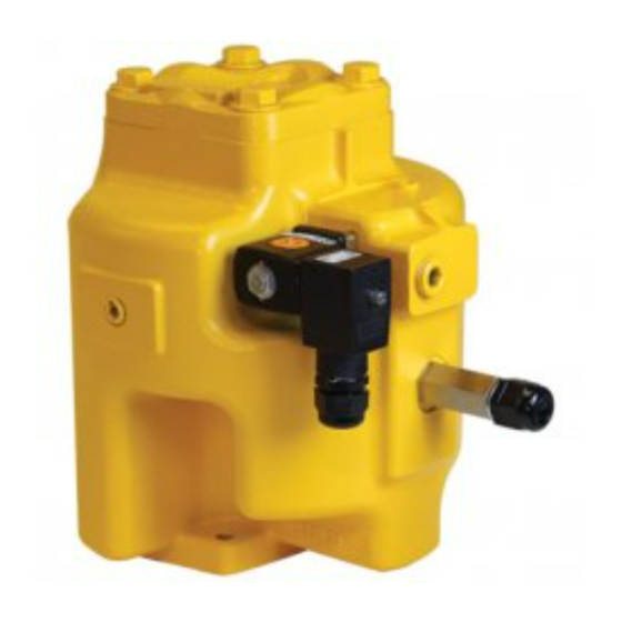
- Page 1 Optical Air Eliminator Installation (US Patent #7000628) and Parts Refined Fuels Applications (A8981 & A8981A) Liquid ControLs Group An IDEX Fluid & Metering Business Installation: M300-20...
-
Page 2: Table Of Contents
Publication Updates and Translations The most current English versions of all Liquid Controls publications are available on our web site, www.lcmeter.com. It is the responsibility of the local distributor to provide the most current version of LC manuals, instructions, and specifica- tion sheets in the required language of the country, or the language of the end user to which the products are shipping . -
Page 3: Specifications
Current: 0.5A maximum Maximum differential pressure • 100PSI (6.9BAR) General Information Class 2 The Liquid Controls Optical Air Eliminator is designed for The Liquid Controls Optical Air Eliminator can be manufac- use with LectroCount Electronic Registers. An optical ® tured for Class 2 aviation applications. The Class 2 optical... -
Page 4: How Optical Air Eliminators Work
Introduction How the Optical Air Eliminator Works A solenoid valve, located at the top of the air eliminator, is either open or closed. When the liquid level is below the optical sensor (Figure 1), and a delivery is initiated, the solenoid valve opens and vents air and vapor to Solenoid Valve - OPEN atmospheric pressure. - Page 5 Introduction How the Optical Air Eliminator Works The figures to the left show a cutaway view of the vent port through the solenoid valve. This port has been designed to optimize the venting of air and vapor from the optical air eliminator.
-
Page 6: Installation
Installation New Installations When ordered with a new meter, the optical air elimina- ½" NPT Port tor is supplied mounted atop a strainer on the inlet side of the meter. An example is the meter with high-capacity strainer, two-stage valve, and LectroCount LCR-II Elec- ®... - Page 7 Installation Retrofit Installations These retrofit instructions will show a system using a Hi-Cap strainer/air eliminator; however, the optical air eliminator may also be installed on other LC strainer as- semblies used for refined petroleum products. Step 1 - Remove Old Air Eliminator and Baffel Cup After the internal pressure has been relieved from the system and the assembly drained of liquid, remove the four bolts and washers used to fasten the old air eliminator to the top...
-
Page 8: Dimensional Drawing
Dimensions ront ottom ptical liminator with apacity trainer Dimensions shown are not for construction use. Consult factory when certified Engineering Drawings are required. -
Page 9: Wiring
Installation Wiring The optical air eliminator requires a LectroCount LCR/ LCR-II Electronic Register with CPU board part number 81920 (LC³ with 81924). If the LectroCount does not contain an 81920 CPU board (LC³ with 81924), this board must be ordered as a replacement to the existing CPU board. - Page 10 Installation Wiring Step 3 - Reassemble Cable Plug Reinstall the terminal block into the cable plug housing in the same orientation you found it. Tighten the strain relief strap inside the cable plug using the two screws. Tighten the cable gland on the bottom of the cable plug so that it seals around the cable.
-
Page 11: Maintenance
Maintenance ! WARNING Before disassembly of any meter or accessory component, ALL INTERNAL PRESSURES MUST BE RELIEVED AND ALL LIQUID DRAINED FROM THE SYSTEM IN ACCORDANCE WITH ALL APPLICABLE PROCEDURES. Pressure must be 0 (zero) psi. Close all liquid and vapor lines between the meter and liquid source. Failure to follow this warning could result in property damage, personal injury, or death from fire and/or explosion, or other hazards that may be associated with this type of equipment. - Page 12 Maintenance Disassembling Step 4 Place the valve body on a flat surface. Using a flat blade screwdriver, remove the two screws which hold the armature guide post and valve body together. Lift the armature guide post off of the valve body. The internal components consist of a plunger and a spring.
-
Page 13: Reassembly
Maintenance Reassembling Step 1 Place the spring inside the plunger and insert the plunger, spring end first, into the armature guide post. Place the ar- mature guide post assembly on the valve body. Fasten the armature guide post to the valve body using the two screws removed earlier. -
Page 14: Troubleshooting
Maintenance ! WARNING Before disassembly of any meter or accessory component, ALL INTERNAL PRESSURES MUST BE RELIEVED AND ALL LIQUID DRAINED FROM THE SYSTEM IN ACCORDANCE WITH ALL APPLICABLE PROCEDURES. Pressure must be 0 (zero) psi. Close all liquid and vapor lines between the meter and liquid source. Failure to follow this warning could result in property damage, personal injury, or death from fire and/or explosion, or other hazards that may be associated with this type of equipment. -
Page 15: Exploded View
Bill of Materials - Exploded View Model Number: A8981 & A8981A Italicized part numbers indicate A8981A (Class 2) parts. If there is no italicized number, the listed part number applies to A8981 & A8981A... - Page 16 Houston, TX 77040 +91 265 2631855 (713) 623-0808 Liquid conTroLS SponSLer 105 Albrecht Drive Lake Bluff, IL 60044 (847) 295-1050 105 Albrecht Drive Lake Bluff, IL 60044-2242 © 2008 Liquid Controls 1.800.458.5262 • 847.295.1050 Pub. No. 500333 Fax: 847.295.1057 (2/12) www.lcmeter.com...
Need help?
Do you have a question about the A8981 and is the answer not in the manual?
Questions and answers