H3C UniServer R4300 G5 User Manual
Hide thumbs
Also See for UniServer R4300 G5:
- Installation, quick start (16 pages) ,
- User manual (401 pages)

Related Manuals for H3C UniServer R4300 G5


Summary of Contents for H3C UniServer R4300 G5
- Page 1 H3C UniServer R4300 G5 Server User Guide New H3C Technologies Co., Ltd. http://www.h3c.com Document version: 6W100-20220118...
- Page 2 The information in this document is subject to change without notice. All contents in this document, including statements, information, and recommendations, are believed to be accurate, but they are presented without warranty of any kind, express or implied. H3C shall not be liable for technical or editorial errors or omissions contained herein.
- Page 3 Preface This preface includes the following topics about the documentation: • Audience. • Conventions. • Documentation feedback. Audience This documentation is intended for: • Network planners. • Field technical support and servicing engineers. • Server administrators working with the Server. Conventions The following information describes the conventions used in the documentation.
- Page 4 Symbols Convention Description An alert that calls attention to important information that if not understood or followed WARNING! can result in personal injury. An alert that calls attention to important information that if not understood or followed CAUTION: can result in data loss, data corruption, or damage to hardware or software. An alert that calls attention to essential information.
- Page 5 Documentation feedback You can e-mail your comments about product documentation to info@h3c.com. We appreciate your comments.
-
Page 6: Table Of Contents
Contents Safety information ·························································································· 1 Safety sign conventions ····································································································································· 1 Power source recommendations ······················································································································· 2 Installation safety recommendations ·················································································································· 2 General operating safety ···························································································································· 2 Electrical safety ·········································································································································· 2 Rack mounting recommendations ·············································································································· 2 ESD prevention ·········································································································································· 3 Cooling performance ·································································································································· 3 Battery safety ·············································································································································... - Page 7 Replacing hardware options ········································································ 27 Common operations ········································································································································· 27 Removing the access panel ····················································································································· 27 Installing the access panel ······················································································································· 27 Removing the chassis air baffle ··············································································································· 28 Installing the chassis air baffle ················································································································· 29 Removing the fan cage ···························································································································· 29 Installing the fan cage ······························································································································...
- Page 8 Installing an NVMe drive ·························································································································· 66 Verifying the replacement ························································································································ 68 Replacing a front drive backplane ···················································································································· 68 Guidelines ················································································································································ 68 Prerequisites ············································································································································ 69 Removing a front drive backplane············································································································ 69 Installing a front drive backplane ·············································································································· 69 Replacing a rear drive backplane ···················································································································· 70 Prerequisites ············································································································································...
- Page 9 Guidelines ·············································································································································· 100 Prerequisites ·········································································································································· 101 Installing a TCM or TPM ························································································································ 101 Enabling the TCM or TPM in the BIOS ·································································································· 102 Configuring encryption in the operating system ····················································································· 102 Replacing a power supply ······························································································································ 102 Guidelines ·············································································································································· 102 Prerequisites ··········································································································································...
-
Page 10: Safety Information
Table 1 Safety signs Sign Description Circuit or electricity hazards are present. Only H3C authorized or professional server engineers are allowed to service, repair, or upgrade the server. WARNING! To avoid bodily injury or damage to circuits, do not open any components marked with the electrical hazard sign unless you have authorization to do so. -
Page 11: Power Source Recommendations
General operating safety To avoid bodily injury or damage to the server, follow these guidelines when you operate the server: • Only H3C authorized or professional server engineers are allowed to install, service, repair, operate, or upgrade the server. •... -
Page 12: Esd Prevention
load or unload a rack. A third person might be required to help align the server if the server is installed higher than check level. • For rack stability, make sure only one unit is extended at a time. A rack might get unstable if more than one server unit is extended. -
Page 13: Battery Safety
Battery safety The server's system board contains a system battery, which is designed with a lifespan of 3 to 5 years. If the server no longer automatically displays the correct date and time, you might need to replace the battery. When you replace the battery, follow these safety guidelines: •... -
Page 14: Preparing For Installation
Table 2 Installation limits for different rack depths Rack depth Installation limits • The H3C cable management arm (CMA) is not supported. • A clearance of 60 mm (2.36 in) is reserved from the server rear to the rear rack door for cabling. - Page 15 Figure 1 Installation suggestions for a 1200 mm deep rack (top view) (1) 1200 mm (47.24 in) rack depth (2) A minimum of 50 mm (1.97 in) between the front rack posts and the front rack door (3) 780 mm (30.71 in) between the front rack posts and the rear of the chassis, including power supply handles at the server rear (not shown in the figure) (4) 800 mm (31.50 in) server depth, including chassis ears (5) 960 mm (37.80 in) between the front rack posts and the CMA...
-
Page 16: Installation Site Requirements
Installation site requirements Airflow direction of the server Figure 2 Airflow direction of the server (1) to (2) Directions of the airflow into the chassis and power supplies (3) to (5) Directions of the airflow out of the chassis and power supplies Temperature and humidity requirements To ensure correct operation of the server, make sure the room temperature and humidity meet the requirements as described in Appendix A Server specifications. - Page 17 Corrosive gas Sources fuel, auto emissions, ore smelting, and sulfuric acid manufacture. Sulfur dioxide (SO ) and sulfur trioxide Combustion of fossil fuel, auto emissions, ore smelting, sulfuric acid manufacture, and tobacco smoke. Sulphur (S) Foundries and sulfur manufacture. Fertilizer manufacture, aluminum manufacture, ceramics Hydrogen Fluoride (HF) manufacture, steel manufacture, electronics device manufacture, and fossil fuel.
-
Page 18: Cleanliness Requirements
71.04-1985 to be meet must also < 2 increase by 1. NOTE: Part per billion (ppb) is a concentration unit. 1 ppb represents a volume-to-volume ratio of 1 to 100000000. Requirements for the non-data center equipment room The corrosive gas concentration for the non-data center equipment room must meet the requirements of class 3C2 of IEC 60721-3-3:2002, as shown in Table Table 5 Corrosive gas concentration limits in the non-data center equipment room... -
Page 19: Grounding Requirements
Requirements for the data center equipment room The concentration of dust participles in the equipment room must meet the ISO 8 cleanroom standard defined by ISO 14644-1, as described in Table 6. Make sure no zinc whiskers are in the equipment room. - Page 20 Table 7 Installation tools Picture Name Description Installs or removes screws inside chassis ears. A T25 Torx screwdriver flathead screwdriver can also be used for this purpose. Installs or removes captive screws on processor T30 Torx screwdriver heatsinks. T15 Torx screwdriver Installs or removes screws on the system board.
- Page 21 Picture Name Description Antistatic clothing Prevents ESD when you operate the server. Ladder Supports high-place operations. Interface cable (such as an Ethernet cable or optical Connects the server to an external network. fiber) Type-C to USB cable Connects to a third party USB Wi-Fi module (Xiaomi) to provide a Wi-Fi hotspot.
-
Page 22: Installing Or Removing The Server
Installing or removing the server Installing the server Installing rails Install the inner rails to the server and the outer rails to the rack. For information about installing the rails, see the document shipped with the rails. Rack-mounting the server Slide the server into the rack. -
Page 23: Installing Cable Management Brackets
Figure 4 Securing the server Installing cable management brackets Install cable management brackets if the server is shipped with cable management brackets. For information about how to install cable management brackets, see the installation guide shipped with the brackets. Connecting external cables Cabling guidelines WARNING! To avoid electric shock, fire, or damage to the equipment, do not connect communication equipment... - Page 24 The server is not shipped with a standard PS2 mouse and keyboard. To connect a PS2 mouse and keyboard, you must prepare a USB-to-PS2 adapter. Procedure Connect one plug of a VGA cable to a VGA connector on the server, and fasten the screws on the plug.
-
Page 25: Connecting An Ethernet Cable
Connecting an Ethernet cable About this task Perform this task before you set up a network environment or log in to the HDM management interface through the HDM network port to manage the server. Procedure Determine the network port on the server. To connect the server to the external network, use the Ethernet port on the network adapter. -
Page 26: Connecting The Power Cord
Secure the Ethernet cable. For information about how to secure cables, see "Securing cables." Connecting the power cord Guidelines WARNING! To avoid damage to the equipment or even bodily injury, use the power cord that ships with the server. Before connecting the power cord, make sure the server and components are installed correctly. Procedure Insert the power cord plug into the power receptacle of a power supply at the rear panel, as shown in... - Page 27 Figure 9 Sliding the cable clamp backward b. Open the cable clamp, place the power cord through the opening in the cable clamp, and then close the cable clamp, as shown by callouts 1, 2, 3, and 4 in Figure Figure 10 Securing the AC power cord c.
-
Page 28: Securing Cables
Figure 11 Sliding the cable clamp forward Securing cables Securing cables to cable management brackets For information about how to secure cables to cable management brackets, see the installation guide shipped with the brackets. Securing cables to slide rails by using cable straps You can secure cables to either left slide rails or right slide rails. -
Page 29: Removing The Server From A Rack
Figure 12 Securing cables to a slide rail Removing the server from a rack Power down the server. For more information, see "Powering off the server." Disconnect all peripheral cables from the server. Extend the server from the rack. a. Open the latches of the multifunctional rack mount ears, as shown by callout 1 in Figure b. -
Page 30: Powering On And Powering Off The Server
LED, see Appendix A Specifications and Support Information. Powering on the server from the HDM Web interface Log in to HDM. For information about how to log in to HDM, see H3C Servers HDM User Guide. Power on the server. a. Select System > Power Management. -
Page 31: Powering Off The Server
Configure automatic power-on for the server. a. Select Power Management > Power Configuration, and then click System Power Restore. b. Select Always power on, and then click OK. For more information, see HDM online help. To configure automatic power-on from the BIOS: Log in to the BIOS. - Page 32 Power off the server. For more information, see HDM online help. Disconnect all power cords from the server. Powering off the server from the remote console interface Log in to HDM. For information about how to log in to HDM, see the firmware update guide for the server. Log in to a remote console and then power off the server.
-
Page 33: Configuring The Server
Configuring the server The following information describes the procedures to configure the server after the server installation is complete. Configuration flowchart Figure 14 Configuration flowchart Start Power on the server (Optional) Configure BIOS Configure RAID Install operating system and drivers Update firmware Powering on the server Power on the server. -
Page 34: Configuring Basic Bios Settings
Installing the operating system and hardware drivers Installing the operating system Install a compatible operating system on the server by following the procedures described in the operating system installation guide for the server. server compatibility with operating systems, visit query tool http://www.h3c.com/cn/Service/Document_Software/Document_Center/Server/. -
Page 35: Installing Hardware Drivers
Installing hardware drivers IMPORTANT: To avoid hardware unavailability caused by an update failure, always back up the drivers before you update them. For newly installed hardware to operate correctly, the operating system must have the required hardware drivers. To install a hardware driver, see the operating system installation guide for the server. Updating firmware IMPORTANT: Verify the hardware and software compatibility before firmware upgrade. -
Page 36: Replacing Hardware Options
Replacing hardware options If you are replacing multiple hardware options, read their replacement procedures and identify similar steps to streamline the entire replacement procedure. This document contains procedures for replacing and installing hardware options. If the replacement and installation operations are similar, only replacement procedures are illustrated. If you refer to a replacement procedure to install a hardware option, remove the corresponding blank in advance. -
Page 37: Removing The Chassis Air Baffle
Install the access panel. a. Place the access panel on top of the chassis, with the pin hole in the locking lever aligned with the guided pin on the chassis, as shown by callout 1 in Figure b. Close the locking lever. The access panel will automatically slide in place, as shown by callout 2 in Figure c. -
Page 38: Installing The Chassis Air Baffle
Figure 17 Removing the chassis air baffle Installing the chassis air baffle Align the notches on the air baffle with the pins on the chassis side panels, as shown by callout 1 in Figure Place the air baffle into the chassis, as shown by callout 2 in Figure Close the hooks marked by blue trapezoids on the chassis air baffle, as shown by callout 3 in Figure... -
Page 39: Installing The Fan Cage
Figure 19 Removing the fan cage Installing the fan cage Gently place the fan cage into the chassis, as shown in Figure Figure 20 Installing the fan cage... -
Page 40: Removing The T-Shape Bracket
Removing the T-shape bracket Use a T15 Torx screwdriver to remove the two screws that secure the T-shape bracket, as shown by callout 1 in Figure Lift the T-shape bracket out of the chassis, as shown by callout 2 in Figure Figure 21 Removing the T-shape bracket Installing the T-shape bracket... -
Page 41: Removing The Blank Above The Power Supplies
Figure 22 Installing the T-shape bracket Removing the blank above the power supplies Hold both ends of the blank and pull it out of the chassis, as shown in Figure Figure 23 Removing the blank above the power supplies... -
Page 42: Installing The Blank Above The Power Supplies
Installing the blank above the power supplies Insert the blank into the chassis along the guide rails until the blank is fully seated, as shown in Figure 24. Figure 24 Installing the blank above the power supplies Removing the riser card blank over PCIe riser connector 1 or The blank removal procedure is the same for PCIe riser connector 1 and connector 2. -
Page 43: Installing The Riser Card Blank Over Pcie Riser Connector 1 Or 2
Figure 25 Removing the riser card blank over PCIe riser connector 1 Installing the riser card blank over PCIe riser connector 1 or 2 The blank installation procedure is the same for PCIe riser connector 1 and connector 2. This section installs the blank over connector 1 as an example. -
Page 44: Removing The Riser Card Blank Over Pcie Riser Connector 3 Or 4
Removing the riser card blank over PCIe riser connector 3 or The blank removal procedure is the same for PCIe riser connector 3 and connector 4. This section installs the blank over connector 4 as an example. To remove the riser card blank, lift the blank out of the chassis, as shown in Figure Figure 27 Removing the riser card blank over PCIe riser connector 4 Installing the riser card blank over PCIe riser connector 3 or 4... -
Page 45: Removing A Power Supply Blank
Figure 28 Installing the riser card blank over PCIe riser connector 4 Removing a power supply blank Hold the blank by the holes with two fingers, and then pull the blank out of the chassis, as shown in Figure Figure 29 Removing a power supply blank... -
Page 46: Installing A Power Supply Blank
Installing a power supply blank Place the power supply blank with the TOP sign facing up, hold the blank by the holes with two fingers, and insert the blank into the slot until you cannot push it any further, as shown in Figure Figure 30 Installing a power supply blank Removing a PCIe module blank... -
Page 47: Removing The Blank From The Ocp Network Adapter Slot
To install a PCIe module blank: Insert the PCIe module blank into the riser card, as shown by callout 1 in Figure Snap the blank tail to insert the standout on the riser card into the blank notch to secure the blank, as shown by callout 2 in Figure Figure 32 Installing a PCIe module blank... -
Page 48: Installing The Blank To The Ocp Network Adapter Slot
Installing the blank to the OCP network adapter slot Hold the handle on the blank, and insert the blank into the slot until you cannot push it any further, as shown in Figure Figure 34 Installing the blank to the OCP network adapter slot Replacing the intelligent security bezel Guidelines The intelligent security bezel is hot swappable. -
Page 49: Installing The Intelligent Security Bezel
CAUTION: To avoid damage to the lock, hold down the key while you are turning the key. Figure 35 Unlocking the intelligent security bezel Press the latch and open the security bezel. Then, pull the right edge of the bezel out of the groove in the right chassis ear to remove the security bezel, as shown in Figure Figure 36 Removing the intelligent security bezel... - Page 50 Figure 37 Installing the intelligent security bezel Lock the security bezel. Insert the key into the lock, press and turn the key 90 degree anticlockwise, and the pull out the key, as shown in Figure CAUTION: To avoid damage to the lock, hold down the key while you are turning the key. Figure 38 Locking the intelligent security bezel...
-
Page 51: Adding A Processor
Adding a processor For information about how to add a processor, see H3C UniServer R4300 G5 Server Processor Installation Quick Start. Replacing a processor WARNING! To avoid bodily injury from hot surfaces, allow the server and its internal modules to cool before touching them. - Page 52 Remove the access panel. For more information, see "Removing the access panel." Remove the chassis air baffle. For more information, see "Removing the chassis air baffle." Remove the processor heatsink: a. Loosen the four captive screws in a diagonal sequence, as shown in Figure Figure 39 Loosening captive screws on the heatsink b.
- Page 53 Figure 40 Opening the clips to unlock the heatsink c. Lift the heatsink slowly to remove it, as shown in Figure CAUTION: The pins on the processor socket are very fragile. Never touch the pins. Any damage to them might require system board replacement.
- Page 54 Figure 41 Lifting the heatsink Remove the processor: a. Lift the locking lever to release the processor, as shown by callout 1 in Figure b. Hold the processor and pull it out from the retaining bracket, as shown by callout 2 in Figure Figure 42 Removing the processor Remove the processor retaining bracket from the heatsink:...
-
Page 55: Installing A Processor
b. Lift the retaining bracket to remove it from the heatsink, as shown by callout 2 in Figure Figure 43 Removing the retaining bracket Use isopropanol wiping cloth to clear the residual thermal grease from the processor top and heatsink, as shown in Figure Figure 44 Clearing the residual thermal grease Installing a processor... - Page 56 Figure 45 Installing the retaining bracket onto the heatsink Figure 46 Locking lever opened or closed on the retaining bracket Smear thermal grease onto the processor: a. Clean the heatsink. Make sure no thermal grease remains on the heatsink top. b.
- Page 57 Figure 47 Smearing thermal grease onto the processor Install the processor onto the retaining bracket. CAUTION: To avoid damage to the processor, always hold the processor by its edges. Never touch the gold contacts on the processor bottom. a. Tilt the processor and align the small triangle on the processor with the alignment triangle on the retaining bracket.
- Page 58 Figure 49 Locking the processor Install the heatsink onto the server: a. Align the alignment triangle on the retaining bracket with the cut-off corner of the processor socket and the pin holes in the heatsink with the guide pins on the processor socket. Lower down the heatsink on the processor socket.
- Page 59 Figure 51 Holding a heatsink b. Press down the heatsink clips at the four corners to lock the heatsink in place. Figure 52 Locking the heatsink c. Use a T30 Torx screwdriver to fasten the four captive screws on the heatsink in a diagonal sequence.
-
Page 60: Verifying The Replacement
Figure 53 Fastening the captive screws Install the chassis air baffle. For more information, see "Installing the chassis air baffle." Install the access panel. For more information, see "Installing the access panel." Rack-mount the server. For more information, see "Rack-mounting the server."... -
Page 61: Guidelines
For example, for a DDR4 DIMM to operate at 3200 MHz, you must also use a processor that can operate at 3200 MHz. For the frequency of a DIMM or processor, use the query tool at http://www.h3c.com/cn/Service/Document_Software/Document_Center/Server/ to filter information by DIMM name or processor name. - Page 62 Make sure all DDR4 DIMMs have the same product code and all PMem DIMMs have the same product code. For information about DIMM product codes, use the query tool available from http://www.h3c.com/cn/Service/Document_Software/Document_Center/Server/. • Depending on the processor and DIMM configuration, use the schemes shown in...
-
Page 63: Prerequisites
Figure 56 Mixed DDR4 and PMem DIMM population schemes for one processor DIMM population Number of Numer of DIMM slots (processor 1) DDR4 PMem 200 DIMMs DIMMs PMem PMem PMem PMem DDR4 DDR4 DDR4 DDR4 PMem DDR4 DDR4 DDR4 DDR4 DDR4 DDR4 PMem... -
Page 64: Installing A Dimm
Remove the server from the rack. For more information, see "Removing the server from a rack." Remove the access panel. For more information, see "Removing the access panel." Remove the chassis air baffle. For more information, see "Removing the chassis air baffle."... -
Page 65: Verifying The Replacement
Rack-mount the server. For more information, see "Rack-mounting the server." Connect the power cord. For more information, see "Connecting the power cord." Power on the server. For more information, see "Powering on the server." (Optional.) Access the BIOS to change the memory mode, if necessary. For more information, see the BIOS user guide for the server. - Page 66 Remove the server from the rack. For more information, see "Removing the server from a rack." Remove the OCP network adapter. For more information, see "错误!未找到引用源。." Remove the power supplies. For more information, see "Removing a power supply." Remove the access panel. For more information, see "Removing the access panel."...
-
Page 67: Installing The System Board
Figure 62 Removing the system board Installing the system board Install the system board: a. Hold the system board handle and slowly place the system board in the chassis. Then, slide the system board toward the server rear until the connectors (for example, USB connectors and the Ethernet port) on it are securely seated, as shown by callout 1 in Figure NOTE:... - Page 68 Figure 63 Installing the system board Reconnect cables to the system board. Remove the installed protective covers over the processor sockets. Hold a cover by the standouts at the two ends and lift it straight up and away from a socket, as shown in Figure Keep the cover for future use.
-
Page 69: Replacing A Sas/Sata Drive
Install the chassis air baffle. For more information, see "Installing the chassis air baffle." Install the access panel. For more information, see "Installing the access panel." Install the removed OCP network adapter. For more information, see "错误!未找到引用源。." 10. Install the removed power supplies. For more information, see "Installing a power supply."... - Page 70 Observe the drive LEDs to verify that the drive is not selected by the storage controller and is not performing a RAID migration or rebuilding. For more information about drive LEDs, see Appendix A Specifications and Support Information. Remove the drive, as shown in Figure To remove an SSD, press the button on the drive panel to release the locking lever, and then ...
-
Page 71: Installing A Sas/Sata Drive
Installing a SAS/SATA drive IMPORTANT: As a best practice, install drives that do not contain RAID information. Attach the drive to the drive carrier. Place the drive in the carrier and then use four screws to secure the drive into place, as shown in Figure Figure 67 Attaching the drive to the drive carrier Install the drive. -
Page 72: Verifying The Replacement
• Verify the drive properties (including capacity) by using one of the following methods: Log in to HDM. For more information, see H3C Servers HDM online help. Access the BIOS. For more information, see the storage controller user guide for the server. -
Page 73: Prerequisites
• Verify the drive properties (including capacity) by using one of the following methods: Log in to HDM. For more information, see H3C Servers HDM online help. Access the BIOS. For more information, see the BIOS user guide for the server. -
Page 74: Replacing An Nvme Drive
NVMe drive in an operating system that does not support hot insertion or managed hot removal of NVMe drives, first power off the server. If an operating system supports hot swapping of NVMe drives, follow these guidelines: •... -
Page 75: Installing An Nvme Drive
a. Press the button on the drive panel to release the locking lever, as shown by callout 1 in Figure b. Pull the drive out of the slot, as shown by callout 2 in Figure Figure 70 Removing the drive Remove the drive carrier. - Page 76 If the operating system supports hot insertion of NVMe drives, see NVMe Drives Online Replacement User Guide. Attach the drive to the drive carrier. Place the drive in the carrier and then use four screws to secure the drive into place, as shown in Figure Figure 72 Attaching the drive to the drive carrier Install the drive:...
-
Page 77: Verifying The Replacement
Figure 74 Installing the drive Install the removed security bezel, if any. For more information, see "Installing the intelligent security bezel." Power on the server. For more information, see "Powering on the server." Verifying the replacement Use the following methods to verify that the drive is installed correctly: •... -
Page 78: Prerequisites
For more information about drive backplanes, see Appendix A Specifications and Support Information. Prerequisites Take the following ESD prevention measures: • Wear antistatic clothing. • Wear an ESD wrist strap and make sure it makes good skin contact and is reliably grounded. •... -
Page 79: Replacing A Rear Drive Backplane
Figure 76 Installing a front drive backplane Connect cables to the drive backplane. Install the removed fan cage. For more information, see "Installing the fan cage." Install all the fan modules. For more information, see "Installing a fan module." Install the access panel. For more information, see "Installing the access panel."... -
Page 80: Installing A Rear Drive Backplane
Disconnect all cables from the rear drive backplane. Remove the rear drive backplane as shown in Figure a. Loosen the captive screw on the rear drive backplane, as shown by callout 1. b. Slide the drive backplane until the notch on the backplane is aligned with the guide pin on the drive cage, and pull the backplane out of the drive cage, as shown by callout 2. -
Page 81: Replacing A Rear Drive Cage
Replacing a rear drive cage Prerequisites Take the following ESD prevention measures: • Wear antistatic clothing. • Wear an ESD wrist strap and make sure it makes good skin contact and is reliably grounded. • Do not wear any conductive objects, such as jewelry or watches. When you replace a component, examine the slot and connector for damages. -
Page 82: Installing A Rear Drive Cage
Figure 80 Removing a 2LFF drive cage Installing a rear drive cage Install a rear drive cage: To install a rear 2SFF drive cage, press the right side of the drive cage against the chassis side panel, place the drive cage into the chassis, and use screws to secure the drive cage. The procedures are similar for installing a rear 2SFF drive cage and a rear 4SFF drive cage. -
Page 83: Replacing Riser Cards And Pcie Modules
To install a rear 2LFF drive cage, press the front of the drive cage against the support brackets, and place the drive cage into the chassis. Then, use screws to secure the drive cage. The procedures are similar for installing a rear 2LFF drive cage and a rear 4LFF drive cage. This section installs a rear 2LFF drive cage as an example. -
Page 84: Prerequisites
If a processor is faulty or absent, the PCIe slots connected to it are unavailable. For more information about riser card, PCIe slot, and processor mappings, see Appendix A Specifications and Support Information. Prerequisites Take the following ESD prevention measures: •... -
Page 85: Installing A Riser Card And A Pcie Module
Figure 84 Removing a PCIe module from the riser card Installing a riser card and a PCIe module Install a PCIe module on the riser card: a. Insert the PCIe module into the slot on the riser card along the guide rails. Snap the module tail to insert the standout on the riser card into the blank notch in the tail to secure the module, as shown by callout 1 in Figure... -
Page 86: Replacing A Storage Controller And A Power Fail Safeguard Module
Figure 86 Installing the riser card Connect cables to the riser card or PCIe modules, if any. Install the access panel. For more information, see "Installing the access panel." Rack-mount the server. For more information, see "Rack-mounting the server." Connect the power cord. For more information, see "Connecting the power cord."... -
Page 87: Guidelines
(PMC or LSI). For information about the available storage controllers and their vendors, use the query tool available from http://www.h3c.com/cn/Service/Document_Software/Document_Center/Server/. Table 9 to identify the supercapacitor available for a storage controller. -
Page 88: Removing A Standard Storage Controller And A Power Fail Safeguard Module
• Wear antistatic clothing. • Wear an ESD wrist strap and make sure it makes good skin contact and is reliably grounded. • Do not wear any conductive objects, such as jewelry or watches. When you replace a component, examine the slot and connector for damages. Make sure the pins are not damaged (bent for example) and do not contain any foreign objects. -
Page 89: Installing A Standard Storage Controller And A Power Fail Safeguard Module
Figure 88 Removing the supercapacitor Installing a standard storage controller and a power fail safeguard module (Optional.) Install a supercapacitor, as shown in Figure a. Install the supercapacitor. Tilt the supercapacitor and insert one end of the supercapacitor into the supercapacitor holder. Pull the clip on the holder and insert the other end into the holder, and then release the clip. - Page 90 Figure 89 Installing a supercapacitor Install the removed flash card on the power fail safeguard module: a. Install the internal threaded studs supplied with the power fail safeguard module on the standard storage controller. b. Install the flash card on the standard storage controller. Align the two screw holes in the flash card with the threaded studs, insert the flash card, and use screws to secure the flash card, as shown in Figure...
-
Page 91: Replacing A Gpu Module
Figure 90 Installing the flash card Install the standard storage controller on the riser card. For more information, see ".Installing a riser card and a PCIe module." Install the riser card on the server. For more information, see ".Installing a riser card and a PCIe module."... -
Page 92: Prerequisites
Table 10 Recommended slots for HHHL GPUs Number of GPUs Recommended slots slot 4 slot 4/5 slot 4/5/7 slot 4/5/7/8 slot 4/5/6//7/8 slot 1/4/5/6/7/8 NOTE: • For more information about slot locations, see Appendix A Specifications and Support Information. • For more information about riser card, PCIe slot, and processor mappings, see Appendix A Specifications and Support Information. -
Page 93: Installing A Gpu Module
Figure 91 Removing the GPU module from the riser card Installing a GPU module Install a GPU module on the riser card. Insert the GPU module into the PCIe slot along the guide rails, and then close the retaining latch. Figure 92 Installing the GPU module on the riser card Reconnect other cables to the riser card, if any. -
Page 94: Replacing A Standard Pcie Network Adapter
Replacing a standard PCIe network adapter WARNING! To avoid bodily injury from hot surfaces, allow the server and its internal modules to cool before touching them. Guidelines To install a standard PCIe network adapter, a riser card is required. For more information about riser card and PCIe module compatibility, see Appendix A Specifications and Support Information. -
Page 95: Guidelines
Guidelines You can install an OCP network adapter in slot 16. For information about the OCP adapter connectors on the system board, see Appendix A Specifications and Support Information. Some operating systems support managed hot removal of specific OCP network adapters. For more information, see Appendix B Managed removal of OCP network adapters. -
Page 96: Replacing A Sata M.2 Ssd And A Sata M.2 Ssd Expander Module
Figure 94 Installing an OCP network adapter Connect external cables to the OCP network adapter. Power on the server. For more information, see "Powering on the server." (Optional.) Configure a network port on the OCP network adapter as the HDM shared network port. -
Page 97: Removing A Sata M.2 Ssd And A Sata M.2 Ssd Expander Module
• Do not wear any conductive objects, such as jewelry or watches. • When you replace a component, examine the slot and connector for damages. Make sure the pins are not damaged (bent for example) and do not contain any foreign objects. Removing a SATA M.2 SSD and a SATA M.2 SSD expander module Power off the server. -
Page 98: Installing A Sata M.2 Ssd And A Sata M.2 Ssd Expander Module
Installing a SATA M.2 SSD and a SATA M.2 SSD expander module Install a SATA M.2 SSD to the SATA M.2 SSD expander module. Insert the connector of the SSD into the socket, slide the locking tab, press the SSD to secure the SSD into place, and then release the locking tab, as shown in Figure Figure 97 Installing a SATA M.2 SSD to the SATA M.2 SSD expander module... -
Page 99: Replacing A Dual Sd Card Extended Module
Connect the power cord. For more information, see "Connecting the power cord." Power on the server. For more information, see "Powering on the server." Replacing a dual SD card extended module Prerequisites Take the following ESD prevention measures: • Wear antistatic clothing. •... -
Page 100: Installing A Dual Sd Card Extended Module
Figure 100 Removing all SD cards from the extended module Installing a dual SD card extended module Install SD cards on the dual SD card extended module. Insert an SD card into the slot and gently press the SD card to secure it in the slot, as shown in Figure 101. -
Page 101: Replacing An Sd Card
Figure 102 Installing the dual SD card extended module Install the removed riser card, if any. Install the access panel. For more information, see "Installing the access panel." Rack-mount the server. For more information, see "Rack-mounting the server." Connect the power cord. For more information, see "Connecting the power cord."... -
Page 102: Installing An Sd Card
Figure 103 Removing the dual SD card extended module Remove each of the SD cards from the extended module. Gently press an SD card to release it and pull the SD card out of the slot. Figure 104 Removing an SD card Installing an SD card Install a new SD card. -
Page 103: Replacing A Chassis Ear
Figure 105 Installing an SD card Install the dual SD card extended module on the server. Align the blue grooves in the extended module with the standout on the side panel of the power supply cage, and insert the extended module into the slot until you hear a click, as shown in Figure 106. -
Page 104: Removing A Chassis Ear
The procedure is the same for replacing the left and right chassis ears, except that you must also remove and install the chassis-open alarm module when replacing the left chassis ear. This section replaces the left chassis ear as an example. Removing a chassis ear Power off the server. -
Page 105: Installing A Chassis Ear
Figure 108 Removing the screws that secure the chassis ear 10. Remove the chassis ear, as shown in Figure 109. a. Remove the four screws that secure the cable protection plate, as shown by callout 1. b. Slide the plate towards the server front, and then remove the plate, as shown by callouts 2 and 3. - Page 106 a. Attach the chassis ear to the server, as shown by callout 1 in Figure 110. b. Close the cable protection plate, as shown by callouts 2 and 3 in Figure 110. c. Fasten the two screws that secure the plate, as shown by callout 4 in Figure 110.
-
Page 107: Replacing A Fan Module
Figure 112 Installing the chassis-open alarm module Connect the cable assembly for front I/O components and the chassis-open alarm module to the system board. Install the fan cage. For more information, see "Installing the fan cage." Install all fan modules. For more information, see "Installing a fan module."... -
Page 108: Installing A Fan Module
Remove the access panel. For more information, see "Removing the access panel." Remove a fan module. Hold the fan module by the notches and pull the fan module out of the chassis, as shown in Figure 113. Figure 113 Removing a fan module Installing a fan module Install a fan module. -
Page 109: Installing And Setting Up A Tcm Or Tpm
Do not remove an installed TCM or TPM. Once installed, the module becomes a permanent part of the system board. • If you want to replace the failed TCM or TPM, remove the system board, and then contact H3C Support to replace the TCM or TPM and the system board. •... -
Page 110: Prerequisites
• H3C is not liable for blocked data access caused by improper use of the TCM or TPM. For more information, see the encryption technology feature documentation provided by the operating system. Prerequisites Take the following ESD prevention measures: •... -
Page 111: Enabling The Tcm Or Tpm In The Bios
Replacing a power supply Guidelines • To avoid damage to hardware, use only H3C approved power supplies. • The server supports 1+1 power supply redundancy. • The power supplies installed on the server must be the same model. If they differ in model, HDM would raise an alarm. -
Page 112: Prerequisites
Prerequisites Take the following ESD prevention measures: • Wear antistatic clothing. • Wear an ESD wrist strap and make sure it makes good skin contact and is reliably grounded. • Do not wear any conductive objects, such as jewelry or watches. When you replace a component, examine the slot and connector for damages. -
Page 113: Installing A Power Supply
Figure 118 Removing the power supply Installing a power supply If only one power supply is present, install the new power supply in the slot for the replaced power supply. To install a power supply: Install a new power supply. Orient the power supply so that the lettering on the label is upright, and then push the power supply into the slot until you hear a click, as shown in Figure 119. -
Page 114: Replacing The Nvme Vroc Module
Figure 119 Installing the power supply Rack-mount the server. For more information, see "Rack-mounting the server." Connect the power cord. For more information, see "Connecting the power cord." Power on the server. For more information, see "Powering on the server." Replacing the NVMe VROC module WARNING! To avoid bodily injury from hot surfaces, allow the server and its internal modules to cool before... -
Page 115: Installing The Nvme Vroc Module
Figure 120 Removing the NVMe VROC module Installing the NVMe VROC module Install a new NVMe VROC module. Insert the NVMe VROC module onto the NVMe VROC module connector on the system board, as shown in Figure 121. Figure 121 Installing an NVMe VROC module Install the access panel. -
Page 116: Replacing The System Battery
Power on the server. For more information, see "Powering on the server." Replacing the system battery WARNING! To avoid bodily injury from hot surfaces, allow the server and its internal modules to cool before touching them. The server comes with a system battery (Panasonic BR2032) installed on the system board, which supplies power to the real-time clock and has a lifespan of 3 to 5 years. -
Page 117: Installing The System Battery
Figure 122 Removing the system battery Installing the system battery Install the system battery. a. Insert the system battery with the plus sign "+" facing up into the system battery holder, as shown by callout 1 in Figure 123. b. Press down the battery to secure it into place, as shown by callout 2 in Figure 123. -
Page 118: Connecting Internal Cables
Connecting internal cables Guidelines Follow these guidelines when connecting the internal cables: • Do not route the cables above the removable components, such as DIMMs. • Route the internal cables without hindering installation or removal of other components or hindering other internal components. •... - Page 119 Figure 124 Connecting the SAS/SATA cable for the front 24LFF drive backplane Connect NVMe data cables for the front 24LFF backplane. Connect the SlimSAS connectors on the backplane to the SlimSAS connectors on the system board. Figure 125 Connecting NVMe data cables for the front 24LFF backplane Connect AUX signal cables for the front 24LFF drive backplane.
- Page 120 Figure 126 Connecting AUX signal cables for the front 24LFF drive backplane Connect power cords for the front 24LFF backplane. Figure 127 Connecting power cords for the front 24LFF backplane Connect SAS/SATA data cables, the power cord and the AUX signal cable for the rear 12LFF backplane.
- Page 121 Figure 128 Connecting SAS/SATA data cables & the power cord & the AUX signal cable for the rear 12LFF backplane (power cord under system board) (1) AUX data cable (2) SAS/SATA data cable 1 (3) SAS/SATA data cable 2 (4) Power cord Figure 129 Connecting the power cord for the rear 12LFF drive backplane (power cord above system board) Connect power cords and AUX data cables for the rear 4SFF Unibay drive backplane and the...
- Page 122 Figure 130 Connecting power cords and AUX data cables for the rear 4SFF Unibay drive backplane and the rear 2LFF drive backplane (1) Power cord for 4SFF UniBay (2) AUX data cable for 4SFF UniBay (3) AUX data cable for 2LFF (4) Power cord for 2LFF Connect SAS/SATA data cables for the rear 4SFF Unibay drive backplane and the rear 2LFF drive backplane.
- Page 123 Figure 132 Connecting NVMe cables for the rear 4SFF Unibay drive backplane Front 24LFF drives+rear 12LFF drives+rear 2SFF drives+rear 4LFF drives This section uses two 8i storage controllers in slots7 and 8 as an example to introduce the cabling method. For more information about the slot locations, see Appendix A Specifications and Support Information.
- Page 124 Connect NVMe data cables for the front 24LFF drive backplane, as shown in Figure 125. Connect AUX signal cables for the front 24LFF drive backplane, as shown in Figure 126. Connect power cords for the front 24LFF drive backplane, as shown in Figure 127.
-
Page 125: Connecting Power Cords For Fan Adapters
Connecting power cords for fan adapters The server supports two fan adapters. Connect power cords to the power adapters as shown in Figure 136. Figure 136 Connecting power cords for fan adapters (1) Power cord 1 (2) Power cord 2 (3) Power cord 3 (4) Power cord 4 Connecting supercapacitor extension cables... -
Page 126: Connecting The Sata M.2 Ssd Data Cables
Connecting the SATA M.2 SSD data cables Figure 138 Connecting the SATA M.2 SSD data cables Connecting the PCIe signal cables The RC-3FHFL-2U-SW-G5 riser card requires PCIe signal cables, whose cabling method varies by riser card installation location. Use Figure 139 Table 11 to identify the cabling method. -
Page 127: Connecting Cables To Chassis Ears
If the slave processor is absent, its corresponding connector on the system board and PCIe slot on the riser card are unavailable. For more information about connectors and slots for slave processors, visit the query tool at http://www.h3c.com/cn/Service/Document_Software/Document_Center/Server/. NOTE: If a processor is absent, the corresponding connectors on the system board and PCIe slots provided by riser cards are unavailable. -
Page 128: Maintenance
Maintenance The following information describes the guidelines and tasks for daily server maintenance. Guidelines • Keep the equipment room clean and tidy. Remove unnecessary devices and objects from the equipment room. • Make sure the temperature and humidity in the equipment room meet the server operating requirements. -
Page 129: Viewing Server Status
H3C Servers HDM User Guide. Collecting server logs For the procedure for collecting server logs, see "Download log" in H3C Servers HDM User Guide. Updating firmware for the server For the procedure for updating the HDM firmware, BIOS, or CPLD, see H3C Servers Firmware... - Page 130 Contents Server specifications ······················································································ 1 Server models and chassis view ························································································································ 1 Technical specifications ····································································································································· 1 Components ······················································································································································· 2 Front panel ························································································································································· 4 Front panel view of the server ···················································································································· 4 LEDs and buttons ······································································································································· 4 Ports ··························································································································································· 6 Rear panel·························································································································································· 7 Rear panel view ·········································································································································...
-
Page 131: Server Specifications
Figures in this document are for illustration only. Server models and chassis view H3C UniServer R4300 G5 server is a 4U rack server with two Intel Ice Lake series processors. The server provides strong storage performance that can satisfy the current and future demands for business expansion of users. -
Page 132: Components
Item Specifications • 1 × embedded 1 Gbps HDM dedicated port Network • connectors 1 OCP 3.0 network adapter connectors (for NCSI-capable OCP 3.0 network adapters) • 6 × USB connectors (two on the system board, two at the server rear, and two at the server front) •... - Page 133 Item Description (1) Chassis access panel (2) OCP network adapter Installed on the OCP slot on the system board. (3) Processor heatsink Cools the processor. Integrates memory and PCIe controllers to provide data processing (4) Processor capabilities for the server. Provides RAID capability to SAS/SATA drives, including RAID (5) Storage controller configuration and RAID scale-up.
-
Page 134: Front Panel
Item Description Works with Intel VMD to provide RAID capability for the server to (29) NVMe VROC module virtualize storage resources of NVMe drives. (30) Processor retaining bracket Attaches a processor to the heatsink. Helps server ventilation. Fans support hot swapping and N+1 (31) Fan redundancy. - Page 135 Figure 4 Front panel LEDs and buttons Table 2 LEDs and buttons on the front panel Item Button/LED Status • Steady green—The system has started. • Flashing green (1 Hz)—The system is starting. • Steady amber—The system is in standby state. •...
-
Page 136: Ports
Figure 5 Security bezel Table 3 Security bezel effect light System status Light status Standby Steady white: The system is in standby state. • Beads turn on white from middle in turn—POST progress. Startup • Beads turn on white from middle three times—POST has finished. •... -
Page 137: Rear Panel
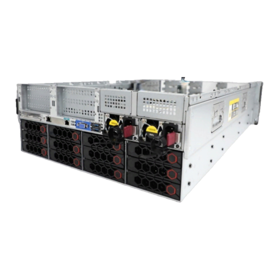
Rear panel Rear panel view Figure 6 shows the rear panel view. Figure 6 Rear panel components Table 5 Rear panel description Item Description PCIe riser bay 1: PCIe slots 1 through 3 PCIe riser bay 2: PCIe slots 4 through 6 PCIe riser bay 3: PCIe slots 7 and 8 (Optional) 2SFF drives Power supply 2... - Page 138 Figure 7 Rear panel LEDs (1) UID LED (2) Link LED of the Ethernet port (3) Activity LED of the Ethernet port (4) Power supply LED for power supply 1 (5) Power supply LED for power supply 2 Table 6 LEDs on the rear panel Status •...
-
Page 139: Ports
Ports Table 7 Ports on the rear panel Port Type Description Connects a display terminal, such as a monitor or VGA connector DB-15 KVM device. The BIOS serial port is used for the following purposes: • Log in to the server when the remote network BIOS serial port RJ-45 connection to the server has failed. - Page 140 Figure 8 System board components Table 8 System board components Item Description TPM/TCM connector (TPM) PCIe riser connector 1 (RISER1 PCIe X32) System battery OCP 3.0 adapter connector (OCP3.0) SlimSAS port 1 (×8 SATA) (SATA PORT) SlimSAS port 2 (×4 SATA) (SSATA PORT) Rear drive backplane AUX connector 9 (AUX9) GenZ port (×2 SATA) (M.2&CD-ROM) AUX connector 7 (AUX7)
-
Page 141: System Maintenance Switch
Item Description Drive backplane AUX connector 2 (AUX2) Fan connector 5 (J65) Front I/O connector (RIGHT EAR) LP SlimSAS port A1/A2 (x8 PCIe4.0, for processor 1) (NVMe-A1/A2) Fan connector 4 (J64) (reserved) LP SlimSAS port A3/A4 (x8 PCIe4.0, for processor 1) (NVMe-A3/A4) Chassis-open alarm module, front VGA, and USB 3.0 connector (LEFT EAR) Fan connector 3 (J63) Drive backplane power connector 3 (PWR3) -
Page 142: Dimm Slots
Figure 9 System maintenance switch Table 9 System maintenance switch description Item Description Remarks • Off (default)—HDM login requires the username and password of a valid HDM For security purposes, turn off the switch after user account. you complete tasks with the default username •... -
Page 143: Fan Adapters
Figure 10 System board DIMM slot layout Fan adapters Fan adapter components Figure 11 shows the fan adapter layout. Figure 11 Fan adapter components... - Page 144 Table 10 Fan adapter components Item Specification Fan module connector 2/4 (J2) Fan module connector 1/3 (J3) Fan module power connector 1/3 (J5) Fan module power connector 2/4 (J6) NOTE: The number of a fan module or fan module power connector varies by the fan module slot that holds the fan adapter.
-
Page 145: Component Specifications
Component specifications For components compatible with the server and detailed component information, visit the query tool at http://www.h3c.com/cn/Service/Document_Software/Document_Center/Server/. About component model names The model name of a hardware option in this document might differ slightly from its model name label. -
Page 146: Dram Dimm Rank Classification Label
DRAM DIMM rank classification label A DIMM rank is a set of memory chips that the system accesses while writing or reading from the memory. On a multi-rank DIMM, only one rank is accessible at a time. To determine the rank classification of a DRAM DIMM, use the label attached to the DIMM, as shown Figure Figure 12 DRAM DIMM rank classification label Table 12 DIMM rank classification label description... -
Page 147: Hdds And Ssds
For more information about OSs that support hot insertion and managed hot removal of NVMe drives, visit compatibility query tool http://www.h3c.com/cn/Service/Document_Software/Document_Center/Server/. Figure 15 shows the location of the LEDs on a drive. -
Page 148: Drive Backplanes
Figure 15 Drive LEDs (1) Fault/UID LED (2) Present/Active LED To identify the status of a SAS or SATA drive, use Table 13. To identify the status of an NVMe drive, Table Table 13 SAS/SATA drive LED description Fault/UID LED status Present/Active LED status Description Steady green/Flashing green... -
Page 149: Front 24Lff Drive Backplane (18Sas/Sata+6Unibay)
• X SAS/SATA+Y UniBay drive backplanes—Support SAS/SATA drives in all slots and support NVMe drives in certain slots. − X: Number of slots supporting only SAS/SATA drives. − Y: Number of slots supporting both SAS/SATA and NVMe drives. For UniBay drive backplanes and X SAS/SATA+Y UniBay drive backplanes: •... -
Page 150: Rear 12Lff Sas/Sata Drive Backplane
Item Specification x4 Mini-SAS-HD upstream connector 7 (SAS-PORT 7) x4 Mini-SAS-HD upstream connector 6 (SAS-PORT 6) x4 Mini-SAS-HD upstream connector 5 (SAS-PORT 5) x4 Mini-SAS-HD upstream connector 2 (SAS-PORT 2) x4 Mini-SAS-HD upstream connector 8* (SAS-PORT 8) x4 Mini-SAS-HD upstream connector 1** (SAS-PORT 1) *The enabling status of this connector varies by the number of storage controllers attached to the drive ... -
Page 151: Rear 4Lff Sas/Sata Drive Backplane
Figure 18 Rear 2LFF SAS/SATA drive backplane (1) x4 Mini-SAS-HD connector (SAS PORT 1) (2) AUX connector (AUX 1) (3) Power connector (PWR 1) Rear 4LFF SAS/SATA drive backplane The PCA-BP-4LFF-2U-G5 rear 4LFF SAS/SATA drive backplane can be installed at the server rear to support four 3.5-inch SAS/SATA drives. -
Page 152: Rear 4Sff Unibay Drive Backplane
Figure 20 Rear 2SFF SAS/SATA drive backplane (1) Power connector (PWR) (2) x4 Mini-SAS-HD connector (SAS PORT) (3) AUX connector (AUX) Rear 4SFF UniBay drive backplane The PCA-BP-4SFF-4UniBay-2U-G5 rear 4SFF UniBay drive backplane can be installed at the server rear to support four 2.5-inch SAS/SATA/NVMe drives. Figure 21 Rear 4SFF UniBay drive backplane (1) SlimSAS connector (x8 PCIe 4.0) (NVMe-3/4) (2) AUX connector (AUX) -
Page 153: Rc-2Hhhl-R3-2U-G5
PCIe slot 4 if the riser card is installed on connector 2. For information about PCIe riser connector locations, see "Rear panel view." RC-2HHHL-R3-2U-G5 Item Specifications PCIe riser connector Connector 3 Slot 7: PCIe4.0 ×16 (8, 4, 2, 1) for processor 2 Slot 8: PCIe4.0 ×16 (8, 4, 2, 1) for processor 2 NOTE: PCIe slots... -
Page 154: Rc-3Fhfl-2U-Sw-G5
Item Specifications Form factors of PCIe modules FHFL Maximum power supplied per PCIe slot 75 W Figure 23 RC-3FHFL-2U-G5 riser card (1) PCIe slot 3/6 (2) PCIe slot 2/5 (3) GPU module power connector (4) PCIe slot 1/4 RC-3FHFL-2U-SW-G5 Item Specifications PCIe riser connector Connector 1 or 2... -
Page 155: Fan Modules
Item Specifications with SlimSAS port 1. Form factors of PCIe modules FHFL Maximum power supplied per PCIe slot 75 W Figure 24 RC-3FHFL-2U-SW-G5 riser card (1) PCIe slot 3/6 (2) PCIe slot 2/5 (3) SlimSAS connector 2 (4) GPU module power connector (5) SlimSAS connector 1 (6) PCIe slot 1/4 Fan modules... -
Page 156: Pcie Slot Numbering
Figure 25 Fan module layout PCIe slot numbering The server supports installing riser cards and OCP network adapters at the rear.. Figure 26 shows the PCIe slot numbers. Figure 26 PCIe slot numbering when riser cards are installed at the rear PCIe modules Typically, the PCIe modules are available in the following standard form factors: •... -
Page 157: Storage Controllers
Power fail safeguard module Not supported Firmware upgrade Upgrade with the BIOS Standard storage controllers more information, visit query tool http://www.h3c.com/cn/Service/Document_Software/Document_Center/Server/. NVMe VROC modules Model RAID levels Compatible NVMe SSDs NVMe-VROC-Key-S 0, 1, 10 All NVMe drives NVMe-VROC-Key-P 0, 1, 5, 10... - Page 158 • UEFI shell—Execute the command. For information about how to execute the command, execute the command. help pci • Operating system—The obtaining method varies by OS. For Linux, execute the command. lspci If Linux does not support the command by default, you must execute the lspci command to install the pci-utils package.
-
Page 159: Environment Requirements
Environment requirements About environment requirements The operating temperature requirements for the server vary depending on the server model and hardware configuration. When the general and component-based requirements conflict, use the component-based requirement. Be aware that the actual maximum operating temperature of the server might be lower than what is stated because of poor site cooling performance. -
Page 160: Product Recycling
Product recycling New H3C Technologies Co., Ltd. provides product recycling services for its customers to ensure that hardware at the end of its life is recycled. Vendors with product recycling qualification are contracted to New H3C to process the recycled hardware in an environmentally responsible way. - Page 161 For product recycling services, contact New H3C at • Tel: 400-810-0504 • E-mail: service@h3c.com • Website: http://www.h3c.com...
-
Page 162: Glossary
An Ethernet adapter, also called a network interface card (NIC), connects the server to the adapter network. Fast Intelligent Scalable Toolkit provided by H3C for easy and extensible server FIST management. It can guide users to configure a server quickly with ease and provide an API interface to allow users to develop their own management tools. - Page 163 Item Description A unit of measure defined as 44.45 mm (1.75 in) in IEC 60297-1. It is used as a measurement of the overall height of racks, as well as equipment mounted in the racks. UniBay drive A UniBay drive backplane supports both SAS/SATA and NVMe drives. backplane VMD provides hot removal, management and fault-tolerance functions for NVMe drives to increase availability, reliability, and serviceability.
-
Page 164: Acronyms
Acronyms Acronym Full name BIOS Basic Input/Output System Cable Management Arm CPLD Complex Programmable Logic Device DCPMM Data Center Persistent Memory Module Double Data Rate DIMM Dual In-Line Memory Module DRAM Dynamic Random Access Memory FIST Fast Intelligent Scalable Toolkit Graphics Processing Unit Host Bus Adapter Hard Disk Drive... - Page 165 Acronym Full name Serial Attached Small Computer System Interface SATA Serial ATA Secure Digital Secure Diagnosis System Small Form Factor sLOM Small form factor Local Area Network on Motherboard Solid State Drive Trusted Cryptography Module Thermal Design Power Trusted Platform Module Unit Identification Ultra Path Interconnect Uninterruptible Power Supply...
- Page 166 Before you begin Before you perform a managed removal of an OCP network adapter, perform the following tasks: • Use the OS compatibility query tool available from http://www.h3c.com/cn/Service/Document_Software/Document_Center/Server/ to identify if the operating system supports managed removal of OCP network adapters. •...
- Page 167 Execute the command, where echo 0 > /sys/bus/pci/slots/slot_number/power represents the number of the slot where the OCP network adapter resides. slot_number Figure 2 Executing the echo 0 > /sys/bus/pci/slots/slot_number/power command Identify whether the OCP network adapter has been disconnected: Observe the port LEDs. If the port LEDs are off, the OCP network adapter has been ...
Need help?
Do you have a question about the UniServer R4300 G5 and is the answer not in the manual?
Questions and answers