Table of Contents
Advertisement
Quick Links
Advertisement
Table of Contents

Related Manuals for THORLABS Vytran GPX4000LZ


Summary of Contents for THORLABS Vytran GPX4000LZ
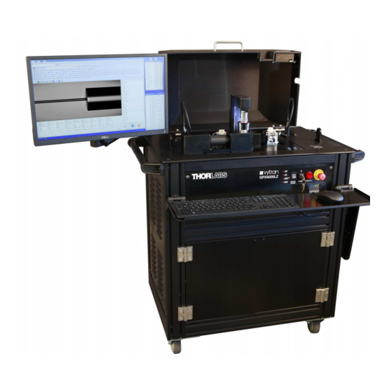
- Page 1 GPX4000LZ Glass Processor User Guide...
-
Page 3: Table Of Contents
GPX4000LZ Glass Processor Table of Contents Chapter 1 Warning Symbol Definitions ..................... 1 Chapter 2 Safety........................... 2 Chapter 3 Description ......................... 4 3.1. Introduction ........................4 3.2. Features ........................4 3.2.1 GPX4000LZ Standard Features ................... 4 3.2.2 GPX4000LZ Optional Features ..................... 4 3.3. - Page 4 Chapter 7 Appendix ........................... 61 7.1. Top Inserts ........................61 7.2. Bottom Inserts ......................62 7.3. Fiber Holder Insert Size Selection Guide ..............63 Chapter 8 Specifications ........................64 Chapter 9 Regulatory ........................67 Chapter 10 Thorlabs Worldwide Contacts ..................68...
-
Page 5: Chapter 1 Warning Symbol Definitions
GPX4000LZ Glass Processor Chapter 1: Warning Symbol Definitions Chapter 1 Warning Symbol Definitions Below is a list of warning symbols you may encounter in this manual or on your device. Symbol Description Direct Current Alternating Current Both Direct and Alternating Current Earth Ground Terminal Protective Conductor Terminal Frame or Chassis Terminal... -
Page 6: Chapter 2 Safety
GPX4000LZ Glass Processor Chapter 2: Safety Chapter 2 Safety WARNING The filament in the glass processor furnace generates intense light when it is in operation. It is strongly advised that the user does NOT look directly at it during splicing or tapering operations. CAUTION: HOT SURFACE The furnace gets extremely hot when the filament is turned on. - Page 7 GPX4000LZ Glass Processor Chapter 2: Safety WARNING Do not stand or climb upon the unit, or on shelves attached to the unit. WARNING After moving the unit into position, lock two of the wheels by pressing down on the black levers. Before attempting to move the unit, unlock the wheels by pulling up on the black levers.
-
Page 8: Chapter 3 Description
GPX4000LZ Glass Processor. This manual provides the basic instructions necessary for operating the glass processor. The Vytran GPX4000LZ Glass Processor is a versatile glass processing platform for the fabrication of splices, tapers, terminations, couplers, and combiners. This systems incorporates a CO... -
Page 9: Gpx4000Lz Accessories
Laser Dump for Laser Warmup 3.4. System Overview The Vytran GPX4000LZ has three basic sub-components, integrated into one system: 1. a splicing and glass processing workstation, 2. a computer (PC) for interface and control and 3. a CO laser with optics to guide and deliver the CO beam to the furnace. -
Page 10: External Workstation Connections
GPX4000LZ Glass Processor Chapter 3: Description 3.4.1 External Workstation Connections All the system interconnections are invisible to the user and contained within the cart and its electronics enclosure. The user will only have to connect the power cable coming out of the cart and the network cable (if desired) as shown in Figure 2. -
Page 11: Fiber Holding Blocks
Multiple sizes and style bottom V-grooves and top U inserts are available to accept all of the standard coating fiber diameters and materials currently being offered. For available insert sizes, please see the selection chart in Chapter 7. In addition to the standard insert sizes, custom inserts can be designed and fabricated. Contact Thorlabs for more information. -
Page 12: End Cap Holders
There are several different devices available for holding end caps in the GPX4000LZ. For end caps with outer diameters of 1.0 mm, 1.5 mm or 2.0 mm, Thorlabs offers steel tubes that can hold the end caps in place using vacuum suction. -
Page 13: Splice Head
GPX4000LZ Glass Processor Chapter 3: Description Figure 6 ECH8C Flexure Clamp Holding An 8 mm End Cap 3.4.4 Splice Head The Splice Head consists of two parts: the Furnace Tower and the Mirror Tower. The splice head moves along the Z-axis to allow for viewing and heating fibers. - Page 14 GPX4000LZ Glass Processor Chapter 3: Description Optical Splice Head The Optical Splice Head is the assembly used for splicing or tapering with the CO Laser system. It consists of a horseshoe-shaped mirror to direct the incoming CO donut-shaped beam to a cone-shaped mirror which focuses the beam on the fibers to be spliced.
- Page 15 Filament Heater Element Filament Assembly Thorlabs supplies standard filaments pre-assembled in a filament body as shown in Figure 12. This is called a filament assembly. Different filament bodies are used with different filaments, and are distinguished by a version number engraved on the front of the housing.
-
Page 16: Mirror Tower
GPX4000LZ Glass Processor Chapter 3: Description The following table lists the standard graphite filament types as a function of the fiber size and application. Item # Filament Material Application Cladding Diameter (Min/Max) FTAV2 80 µm / 250 µm FTAV4 125 µm / 600 µm Splice FTAV5 250 µm / 1000 µm... -
Page 17: Imaging System
GPX4000LZ Glass Processor Chapter 3: Description 3.4.6 Imaging System The GPZ4000LZ Glass Processor is equipped with an automated camera assembly used for imaging the fibers. This tower is capable of moving forwards and backwards as well as up and down. It is equipped with a ring illuminator that provides backlighting for the front and back views of the fiber when using the 5X and 10X objectives and is not used when using the 2X objective. -
Page 18: Chapter 4 Initial Installation, Setup, Introduction And Training
Chapter 4 Initial Installation, Setup, Introduction and Training The initial GPX4000LZ system installation and setup will be performed at the customer site by a Thorlabs Service Engineer. Upon successful uncrating and installation, the Service Engineer will commission the system based on the customer’s specific applications request, as specified on the purchase order. -
Page 19: Chapter 5 Operation
GPX4000LZ Glass Processor Chapter 5: Operation Chapter 5 Operation 5.1. System Power The GPX4000LZ is turned on using the rocker switch on the left side of the unit. This switch powers up the electronics enclosure, two exhaust fans, and the vacuum pump. Power is delivered to other system components as well, but they will not turn on until other switches on the control panel are moved to the “ON”... -
Page 20: Back Panel
GPX4000LZ Glass Processor Chapter 5: Operation 5.3. Back Panel The back panel has the following ports: • An opening with a power cable for accessories such as the LDC401, which the user may wish to place on a shelf attached to the cart. •... - Page 21 GPX4000LZ Glass Processor Chapter 5: Operation Figure 17 FFS3 GUI Main Screen The following sections will explain each of these components in detail. Rev I, September 15, 2021 Page 17...
-
Page 22: Main Menu
GPX4000LZ Glass Processor Chapter 5: Operation 5.5.1 Main Menu a. File The File menu is structured as shown. Open: Open a new splice data file. Open Recent: Shows the files opened recently. Save: Save the current settings to the current splice data file. - Page 23 GPX4000LZ Glass Processor Chapter 5: Operation b. View The View menu allows the user to display or hide user interface elements such as toolbars, data windows Tension Monitor and guides associated with the camera image (such as crosshairs, alignment guides and centering guides). The "Processes Toolbar", "Macro Toolbar"...
- Page 24 GPX4000LZ Glass Processor Chapter 5: Operation c. Configuration The Configuration Menu provides access to user interface properties and GPX machine configuration setup. The Toolbars submenu allows the user to modify the contents of FFS3’s toolbars. By selecting Edit Processes Bar, the user can choose which processes will be displayed on the Process Bar.
- Page 25 GPX4000LZ Glass Processor Chapter 5: Operation Selecting the Edit Quick-Open File Bar item allows the user to add or remove splice files from the Quick-Open File Bar. The Image submenu provides access to all properties related to the camera and imaging. In the CCD Camera property window, the view settings allow the user to control the color and visibility of all the cursors and guides in the...
- Page 26 GPX4000LZ Glass Processor Chapter 5: Operation Auto-Exposure Properties provide access to the target exposure level (image brightness) in both side and end views. The Objective Lens Setup submenu opens up for two further items, Lens Selection and Lens properties. Each objective lens has its own group of settings.
- Page 27 GPX4000LZ Glass Processor Chapter 5: Operation The Mechanical submenu provides access to machine configuration settings Home to View Distance sets the distance between the splice heads home position and its viewing position. The Fiber Holding Block Home Positions determine the final positions the X and Y axis motors move to after being homed.
- Page 28 GPX4000LZ Glass Processor Chapter 5: Operation Load Fibers Properties and Load Taper Properties allow the user to set the fiber holding block’s Z position used for loading the fiber prior to performing a splice or taper. Returning to the main Configuration menu: Argon flow has three rates.
- Page 29 GPX4000LZ Glass Processor Chapter 5: Operation Selecting GPX configuration allows the user to specify the GPX4000LZs mode of operation (either CO GPX Laser Fusion, CO GPX End Cap or CO GPX Filament Fusion). GPX 3000 series configuration should only be selected when using GPX 3000 series machines with no CO laser.
-
Page 30: Command Bar
GPX4000LZ Glass Processor Chapter 5: Operation e. Reset The Reset Menu allows the user to reset, initialize, or stop the GPX. f. Execute The Execute menu can be used to perform key splicing functions. For descriptions of these functions, see "Illustrated Toolbar" below. g. -
Page 31: Camera Bar
GPX4000LZ Glass Processor Chapter 5: Operation 5.5.3 Camera Bar • The "Exposure" button automatically adjusts the image illumination so that the background is set to the specified brightness. To change the brightness setting, right click the button and click "View Properties" and change the exposure value. -
Page 32: Process Bar
GPX4000LZ Glass Processor Chapter 5: Operation 5.5.4 Process Bar The Process Bar allows the user to execute built-in processes such as "Align," "Gap," and "Laser Warm-up." Additional processes can be added. Right click on this bar and this menu will appear: Select "Toolbar Properties"... -
Page 33: Quick Open File Bar
GPX4000LZ Glass Processor Chapter 5: Operation 5.5.6 Quick Open File Bar This toolbar allows the user to quickly access the most commonly used files. Right click on the open space on the toolbar, the "File List" window will show to allow user to add or delete the files on the toolbar. - Page 34 GPX4000LZ Glass Processor Chapter 5: Operation Active alignment : Executes an Active Alignment using an (external) light source and power meter. The power meter must be connected to one of the GPXs "Analog" ports. The analog input reading can be configured under Configuration - Analog Input Configuration with the Channel set to the appropriate port.
-
Page 35: Splice Process List
GPX4000LZ Glass Processor Chapter 5: Operation 5.5.8 Splice Process List The Splice Process List contains the process / command sequence executed by the "One Button Process". See section 5.10 for more information. 5.5.9 Camera Image The Camera Image displays a live video feed from the GPX camera. The image below shows the GPX in side view (front or back). -
Page 36: Movement Control Bar
GPX4000LZ Glass Processor Chapter 5: Operation 5.5.10 Movement Control Bar The nine boxes in the Movement Control Bar allow the user to manually move the fiber handlers and splice head by clicking on the forward and back arrows. The radio buttons labeled "Fine", "Medium" and "Coarse" allow the user to decide how much motion should occur with every click of an arrow. - Page 37 GPX4000LZ Glass Processor Chapter 5: Operation The "Splice Head" box enables movement of the splice head left or right. Positive motion is to the right. The number shown is the position of the Splice Head in microns. Where "0" indicates the View position. The "Right Rotation"...
-
Page 38: Status Bar
GPX4000LZ Glass Processor Chapter 5: Operation 5.5.11 Status Bar The status bar (at the bottom of FFS3s main window) indicates the status of the machine. Ready/Busy Indicator: When the bottom bar is green and the window reads "Ready," the unit is ready to execute new commands. When the top bar is red, the unit is not responding, and is either busy or needs to be initialized. -
Page 39: Initialization And Shutdown
GPX4000LZ Glass Processor Chapter 5: Operation 5.6. Initialization and Shutdown To turn on the glass processor workstation, first turn on the main power switch on the cart. This will turn on the computer automatically. Then press the device power switch on the front panel and turn the laser key to start the Laser. -
Page 40: Storage And Transportation
GPX4000LZ Glass Processor Chapter 5: Operation 5.7. Storage and Transportation When preparing the glass processor workstation for storage, the following precautions are necessary: Shut down the unit according to the procedure described in the previous section If it is open, close the cover. Remove the network cable from the wall socket, coil it, and attach it to the cart using the Velcro strip near it. - Page 41 GPX4000LZ Glass Processor Chapter 5: Operation If the drop shelf is raised, fold it down by pulling down on both braces at the same time. Be careful not to pinch the web of skin between your thumb and index finger! To avoid doing this, pull down on both braces at the same time, and keep your skin out of the joint area.
-
Page 42: System Configuration
5.8. System Configuration The Vytran GPX4000LZ system is capable of operating with multiple furnace types (fusion sources) – these include the CO laser optical heads for either splicing or for end-cap fusion and the various filament fusion heads. The FFS3 software maintains separate settings for each configuration and allows the user to easily switch between saved configurations. -
Page 43: Co End-Cap Head Configuration
GPX4000LZ Glass Processor Chapter 5: Operation 5.9.2 CO End-Cap Head Configuration When the user decides to set the system to be in the End-cap Head Configuration with the desired lens objective setting and installed the proper objective on the camera tower and the correct optical head on the furnace tower, the system is ready to be calibrated to be used for splicing end caps. -
Page 44: Steps Of A Basic Splice With One Button Process
GPX4000LZ Glass Processor Chapter 5: Operation Figure 21 Filament Normalization Execute a Splice or Taper The user can now open the splice file or taper file he desires to execute, prepare fibers according to desired process and press the blue "One Button Process" to execute the routine automatically based on the list of processes defined in the file “splice process list”. -
Page 45: Modifying The Splice Routine
GPX4000LZ Glass Processor Chapter 5: Operation Figure 22 Splice Process List The next step is to load a set of fibers into the glass processor. Place the fibers into the fiber holding blocks utilizing the transfer inserts described in Section: 3.4.2. Then press the Load Fibers button to bring the fibers into the correct viewing position. -
Page 46: Measurement Tools
GPX4000LZ Glass Processor Chapter 5: Operation Figure 23 Splice Process List The Available Processes are controlled by the software library and input to the routine using the Process Add button. The Available Command Scripts listed are any of the buttons in the Macro toolbar (See Section 5.5). The Command Script Copy (+) button will copy the command script in its current form and save it in the file, even if the macro button is removed. -
Page 47: End View Quality Tool
GPX4000LZ Glass Processor Chapter 5: Operation 5.11.2 End View Quality Tool The End View Quality Tool provides a software magnified view of a fiber end face together with a small collection of measurement tools to assist in assessing fiber quality and measuring fiber artifacts. Figure 24 End View Quality Tool Window The main window consists of a toolbar containing the measurement tools and a scrollable viewing window with... - Page 48 GPX4000LZ Glass Processor Chapter 5: Operation Figure 26 Click-Measure Tool Window A tool bar provides access to the Click-Measure Tools built in features. Figure 27 Click-Measure Toolbar From left to right: • Rectangle: Draws a rectangle overlay with annotated left, top and diagonal lengths. •...
-
Page 49: Hot View Imaging
GPX4000LZ Glass Processor Chapter 5: Operation 5.12. Hot View Imaging Hot View Imaging provides the ability to watch the splice or taper being formed in real time. When in Filament Configuration, a pair of neutral density filters (attached to the ring illuminator) are moved in front of the lens to prevent light from the filament saturating the camera. -
Page 50: Laser Controls
GPX4000LZ Glass Processor Chapter 5: Operation 5.13. Laser Controls 5.13.1 Laser On and Laser Warm-up Two similar processes, "Laser On" and "Laser Warm Up" which differ only by the length of time applied, allow the user to independently turn On the Laser at a specified power level for a specified duration. The typical values for the "Laser Warm Up"... -
Page 51: Active Rotation Alignment
GPX4000LZ Glass Processor Chapter 5: Operation Figure 30 PM alignment settings To begin the process, select the Alignment menu then select "Enable PM Alignment". Select "PM," and the PM alignment window will be displayed. This window consists of 4 parameters for both the left and the right fiber. Enter the fiber cladding diameter, fiber type and the two PM geometry parameters as indicated in the below table. -
Page 52: Multiple-Stage And Multiple File Splicing
GPX4000LZ Glass Processor Chapter 5: Operation The active rotation alignment method begins with a normal edge alignment, but does not execute the "Auto Gap" process. Before beginning an active rotation alignment, make sure the light source and polarization analyzer are attached correctly to the 'Analog 2' output. -
Page 53: Drawing Tapers
GPX4000LZ Glass Processor Chapter 5: Operation 5.14.8 Drawing Tapers A fiber may be tapered by heating it to its softening point and applying a tensile force. As the fiber elongates, its cross sectional area will be reduced accordingly. A taper is created by passing the fiber through the fusion source while pulling on it by driving the fiber holding blocks at different velocities. - Page 54 GPX4000LZ Glass Processor Chapter 5: Operation reduces the pulling force on the fiber until finally it is no longer stretching it at all. This creates what is called the "up taper". This tapering process is in fact similar to a fiber drawing process, where the preform enters the furnace at a slow velocity and is pulled at a higher rate, creating the smaller diameter fiber.
- Page 55 GPX4000LZ Glass Processor Chapter 5: Operation The last tab within the Taper Properties window, shown in Figure 36 contains the Taper Load Positions tab. This tab allows the user to specify the starting positions of the fiber holding blocks and the furnace before the tapering process begins.
-
Page 56: Tension Monitor
GPX4000LZ Glass Processor Chapter 5: Operation 5.14.10 Tension Monitor The Tension Monitoring System is used in all Vytran glass processors to provide feedback on the taper process. At system turn on, the tension monitor (shown in Figure 37) needs to be zeroed to ensure proper reading of tension being applied to the fiber. -
Page 57: Thermal Core Expansion
Users are advised to contact Thorlabs for assistance with these applications. 5.14.13... -
Page 58: Taper Tension Process
GPX4000LZ Glass Processor Chapter 5: Operation 5.14.14 Taper Tension Process A user can automatically apply a predefined tension on a fiber (or pair of spliced fibers) loaded on a glass processor. This process (shown in Figure 39) requires the user to input the target tension in grams as well as the tension tolerance (typically a value from 1 g to 2 g). -
Page 59: Chapter 6 Maintenance
GPX4000LZ Glass Processor Chapter 6: Maintenance Chapter 6 Maintenance 6.1. General Care The simple procedures and safeguards outlined in this section will help maintain the glass processor workstation in working condition. 6.2. Keep the System Clean The system should be kept clean at all times; dirt particles trapped in the furnace and fiber holder blocks can cause problems during operation. -
Page 60: Cleaning The Fiber Holding Block Insert
GPX4000LZ Glass Processor Chapter 6: Maintenance The top insert, however, is held in place with setscrews. These two set screws are located in the back of the lid and must be loosened before the top insert can be replaced. 6.3.2 Cleaning the Fiber Holding Block Insert Debris in the fiber holding block v-grooves may interfere with fiber positioning. - Page 61 GPX4000LZ Glass Processor Chapter 6: Maintenance 6. Remove the 2 screws that secure the filament to the furnace body using a 5/64" hex key or ball driver (See Figure 44). Figure 44 Remove filament body screws using a 5/64" hex key or ball driver. 7.
-
Page 62: Changing A Laser Furnace
GPX4000LZ Glass Processor Chapter 6: Maintenance 6.4.2 Changing a Laser Furnace Note: If replacing a filament furnace, see Section 6.4.1 for instructions on removing the filament furnace before installing the laser furnace. 1. Switch the glass processor on and initialize. 2. -
Page 63: Changing The Lens Objective
GPX4000LZ Glass Processor Chapter 6: Maintenance 6.5. Changing the Lens Objective To change the lens objective, ensure to first run the “Lens Home” routine to have the camera tower in the back of the system. Unplug the ring illuminator from the under-arm of the camera tower and remove it by loosening the four set screws holding it to the objective. -
Page 64: Cleaning The Mirrors
Use a clean cotton swab and lens cleaner to remove debris from the mirror surface RMA Process Contact Thorlabs for information on requesting an RMA for a purchased GPX4000LZ glass processor. Please refer to the document GPX4000LZ Crating for instructions on packing up the system for transport or storage. -
Page 65: Chapter 7 Appendix
GPX4000LZ Glass Processor Chapter 7: Appendix Chapter 7 Appendix 7.1. Top Inserts The GPX4000LZ CO Laser Glass Processor requires fiber holder inserts to be placed in the fiber holding blocks in order to clamp the fibers during the splicing process. Fiber holder top inserts sit in the lid of the fiber holding blocks and come in a variety of groove sizes. -
Page 66: Bottom Inserts
GPX4000LZ Glass Processor Chapter 7: Appendix 7.2. Bottom Inserts Fiber holder bottom inserts sit in the bottom section of the fiber holding blocks and come in a variety of groove sizes. They can be used to clamp the cladding, coating, or buffer of the fiber. The top inserts (sold above) and bottom inserts can be paired in a variety of combinations to accommodate all fiber sizes compatible with the glass processor, as shown in Figure 56. -
Page 67: Fiber Holder Insert Size Selection Guide
GPX4000LZ Glass Processor Chapter 7: Appendix 7.3. Fiber Holder Insert Size Selection Guide Figure 56 indicates the minimum and maximum diameters that can be accommodated by different combinations of top and bottom inserts. It also indicates how far offset the fiber will be for recommended combinations of top and bottom inserts. -
Page 68: Chapter 8 Specifications
GPX4000LZ Glass Processor Chapter 8: Specifications Chapter 8 Specifications Operating Mode Laser Mode Filament Mode Heat Source Specifications Laser Wavelength 10.55 µm (Minimum) 10.63 µm (Maximum) Laser Output Power 40 W Laser Safety Features Metal Cover with Interlock Class 1 Enclosure Automatic Laser Power Cutoff Triple Redundancy Safety Measures Laser Beam Control... - Page 69 GPX4000LZ Glass Processor Chapter 8: Specifications Operating Mode Laser Mode Filament Mode Tapering Tapering Length Up to 140 mm (Max) Up to 150 mm (Max) Tapering Ratio (Max) Adiabatic Tapers up to 1:10 (Ratios Up to 1:150 Possible) Tapering Speed 1 mm/s (Typical) Adiabatic Tapering Loss <0.2 dB (Typical)
- Page 70 Thorlabs supplies a high purity PTFE gas line and a large gas regulator with the GPX4000LZ for use in filament mode. These are for use with a large gas tank (not available from Thorlabs) which has a CGA-580 output port; a DIN 477 Number 6 output port connector is also included.
-
Page 71: Chapter 9 Regulatory
Waste Treatment is Your Own Responsibility If you do not return an "end of life" unit to Thorlabs, you must hand it to a company specialized in waste recovery. Do not dispose of the unit in a litter bin or at a public waste disposal site. -
Page 72: Chapter 10 Thorlabs Worldwide Contacts
GPX4000LZ Glass Processor Chapter 10: Thorlabs Worldwide Contacts Chapter 10 Thorlabs Worldwide Contacts For technical support or sales inquiries, please visit us at www.thorlabs.com/contact for our most up-to-date contact information. USA, Canada, and South America UK and Ireland Thorlabs, Inc. - Page 73 www.thorlabs.com...
Need help?
Do you have a question about the Vytran GPX4000LZ and is the answer not in the manual?
Questions and answers