Garmin GNS 480 Pilot's Manual
Color gps/waas/nav/com
Hide thumbs
Also See for GNS 480:
- Installation manaul (200 pages) ,
- Installation manual (186 pages) ,
- Maintenance manual (78 pages)
Table of Contents
Advertisement
Quick Links
Advertisement
Table of Contents

Related Manuals for Garmin GNS 480


Summary of Contents for Garmin GNS 480
- Page 1 GNS 480 color GPS/WAAS/NAV/COM pilot’s guide DRAFT...
- Page 2 Information in this document is subject to change without notice. Garmin reserves the right to change or improve its products and to make changes in the content with- out obligation to notify any person or organization of such changes or improvements. Visit the Garmin Web site (www.garmin.com) for current updates and supplemental information concerning the use and operation of this and other Garmin products.
-
Page 3: Introduction
480 is a precision electronic NAVigation AID (NAVAID), any NAVAID can be misused or misin- terpreted and therefore become unsafe. CAUTION: Use the GNS 480 at your own risk. To reduce the risk of unsafe operation, carefully review and understand all aspects of this Owner’s Manual and the Flight Manual Supplement, and thoroughly practice basic operation prior to actual use. -
Page 4: Accessories And Packing List
Your Garmin dealer will perform the installation and configuration of your new GNS 480. After installation, the NavData card will already be installed into the unit. The GNS 480 will be secured in the mounting tube with the proper wiring connections. Have your dealer answer any questions you may have about the installa-... -
Page 5: Welcome
The Getting Started chapter provides information such as an overview of unit features and how to turn the unit on and adjust the backlight. The GNS 480 also contains a simulator mode to help you get acquainted with its functions and features. -
Page 6: Table Of Contents
Perform a RAIM Prediction ... 19 Moving Map Mode (MAP) ... 20 True North ... 20 Moving Map Mode Menu Items ... 21 GNS 480 Map Mode Nav Data Options ... 22 Basic Operation ... 24 Nav/HSI Display (NAV) ... 31 Panning (PAN) ... 33 Range ... - Page 7 Recall (RCL) ... 50 Flip/Flop ... 50 ID/To/Fr ... 50 Back Course ... 50 Audio ... 50 User ... 50 Save Channel... 50 Test Log ... 51 Transponder Control (XPDR) ... 52 Ident ... 52 Standby ... 52 ON ... 52 ALT ...
- Page 8 Care Information ... 133 Cleaning the Unit ... 133 Battery Replacement ... 133 Display Backlight... 133 Appendix ... 133 Garmin Data Cards ... 134 Installing and Removing Data Cards ... 134 Glossary ... 136 WAAS ... 143 Safety Information ... 143 What is WAAS? ...
-
Page 9: Getting Started
VFR and IFR operations. This Pilot’ s Guide covers the details, so you can get the most out of your GNS 480 (CNX80), quickly. For more details and examples, refer to the GNS 480 (CNX80) Computer-Based Training (CBT) compact disc and in- flight demo DVD which are provided for your convenience. These documents and the Quick Reference Guide,... -
Page 10: Controls
Power/Volume The knob at the top left corner of the GNS 480 controls power on/off and the radio volume. Push the PWR/VOL knob in to turn power on. Pull the knob out to turn power off. When the power knob is pulled out, a time-out message and counter will appear for five seconds. - Page 11 Selects the moving Map mode. Press MAP twice to view Map page 1. Turn the Large knob to view all four MAP pages. The function and menu item smart keys access more features. Direct-To Selects the Direct-To page. Menu options allow setting up Direct-To (D->), setting a customized holding pattern around a waypoint (Hold), Course To (CrsTo) a waypoint, Course From (CrsFr) a waypoint, OBS mode uses input from your CDI Course Selector, and activating a given leg of your active flight plan (FlyLeg).
-
Page 12: Datacard
When fully inserted, the data card and eject button will be flush and slightly recessed into the bezel. When contacting your dealer or the Garmin customer service staff, eject the data card and write down the information shown on the label. -
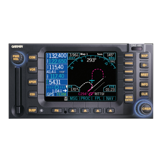
Page 13: Display
Getting Started Display The GNS 480 uses a high-resolution color display to provide information about the different functions. Infor- mation and “smart keys” unique for each mode of operation are displayed. Sample displays with a description of common elements are shown below. -
Page 14: Using The Moving Map
Getting Started Using the Moving Map The Map mode provides a moving map for a graphic display of your flight including the surrounding area, as well as navigation information to aid your situational awareness. You can customize each of the four Map pages for the Map range and the information displayed, such as Airports, VORs, NDBs, Intersections, User Waypoints, Airspace, Traffic from TIS or Skywatch, Hi and Lo Airways, Flight Plan course line, or Nav infor- mation items. - Page 15 The following symbols are used on the map display to depict active legs of flight, waypoint types, and your aircraft. Turn Left for next flight plan leg Turn Right for next flight plan leg No course change Left Procedure Turn Outbound Arc to the Left Arc to the Right...
- Page 16 Getting Started...
- Page 17 Getting Started...
- Page 18 Getting Started...
-
Page 19: Annunciations
The Dead Reckoning annunciator appears on the left side of the map display when GPS position is unavailable and the GNS 480 is in Dead Reckoning mode. Dead Reckoning mode will continue until GPS position is restored or the first Pilot Nav leg is reached. - Page 20 HDG xx° ing is shown. If heading information is not available, the field is dashed. CDI Window: Guidance is not provided on this leg by the GNS 480. Use other flight instruments to fly PILOT NAV this leg. TFC, TFC Fail, TFC STBY, Status of the external traffic source.
-
Page 21: Starting Up
GNS 480 to establish your position. 3. The GNS 480 performs a number of tests at startup to ensure proper operation. You may press SKIP to bypass the startup tests, however, completing these tests is required for IFR flight. Any failures will be noted by a message. -
Page 22: View Checklists
Getting Started The database information can be checked after start-up in the SW Version page of the System function. Press the Menu/Enter key to continue after you have verified the dates. Valid databases are in green. The database being used has an asterisk (*) next to it, if there are two databases. Expired databases are amber. View Checklists Use a checklist to review preparation for flight. -
Page 23: Using The Remote Transponder
The Transponder Control Mode will allow you to control a compatible remotely mounted transponder from Press XPDR to activate Transponder mode. the GNS 480 front panel. Change the Transponder (Squawk Code) - Two Methods 1. Turn the Large knob to highlight the Squawk Code. -
Page 24: Nav Terms Diagram
Getting Started Nav Terms Diagram Flight Plan Terms Diagram... -
Page 25: Create A New Flight Plan (Quick Method)
The Flight Planning function lets you set up and store flight plans where you can name the flight plan, insert a series of waypoints, and then add comments. The Active flight plan is the flight plan that the GNS 480 is currently using for navigation guidance. -
Page 26: Find A Nearest Waypoint
Getting Started Nearest waypoint search - Airport (TWR/CTAF - Frequencies) Nearest airport frequencies Find a Nearest Waypoint The Nearest (NRST) Waypoint Search function allows you to search for the 20 waypoints nearest to your pres- ent position in each of eight waypoints types: Airport, VOR, NDB, INT, User, FSS (Flight Service Station), Air- space, and Air Route Traffic Control Center (ARTCC). -
Page 27: Inserting Terminal Procedures And Approaches . 19 Perform A Raim Prediction
Inserting Terminal Procedures and Approaches After creating your flight plan, you can select an approach, departure, or arrival procedure so the GNS 480 can guide you through the flight plan. You may also make adjustments in Flight Edit mode. 1. Press the PROC function smart key for Procedure Mode. The Origin and Destination waypoint of your active flight plan are shown. -
Page 28: Moving Map Mode (Map)
Basic Operation Moving Map Map Mode - Page 1 True North indication in Map Mode Moving Map Mode (MAP) The Map mode provides a moving map for a graphic display of your flight including the surrounding area as well as navigation information. Maps are generally drawn with Ground Track magnetic North at the top of the display (Up). -
Page 29: Moving Map Mode Menu Items
Moving Map Mode Menu Items Menu Item Airports, VORs, NDBs, Intersections, User Waypoints, Lo and Hi Airways Airspace Traffic Flight Plan Declutter Nav Data/Sel Data Description Solid reversed label means identifier and location symbol are displayed. A bold outline means only the location symbol will be displayed. -
Page 30: Gns 480 Map Mode Nav Data Options
The following table shows the choices of the options you can make for setting up the Map Mode display in your GNS 480. You can customize the Nav information displayed on the left side of the display for Map Mode pages 2, 3, and 4. - Page 31 Selectable Nav Data Fields for Map Pages 2-4 Option Name Abbrev. Description Altitude Baro-corrected pressure altitude. Value is dashed out when there is no valid source. Bearing Bearing to station for the active waypoint. If the active leg is a pilot nav leg or heading leg, or position is invalid, this will be dashed.
-
Page 32: Basic Operation
Basic Operation Moving Map Selectable Nav Data Fields for Map Pages 2-4 Option Name Abbrev. Description Estimated Dest ETA The estimated time of arrival to the Time of final destination waypoint is based Arrival at Final upon ground speed. If the active leg is Destination not part of the flight plan (ie direct-to outside flight plan), ground speed... - Page 33 Selectable Nav Data Fields for Map Pages 2-4 Option Name Abbrev. Description Estimated Fuel Dest FUEL The estimated fuel remaining at the Remaining at final destination waypoint using the Final flight plan information estimated Destination fuel flow, and ground speed. If the active leg is not part of the flight plan (ie direct-to outside the flight plan), ground speed is less than or equal to...
- Page 34 Basic Operation Moving Map Selectable Nav Data Fields for Map Pages 2-4 Option Name Abbrev. Description Desired Track This is the current DTK to the active waypoint. If the current leg is a pilot nav leg or heading leg, or position is invalid, then the DTK will be dashed.
- Page 35 Fuel FUEL REM For FADC that provide fuel remaining, Remaining the GNS 480 shall use the report value from the FADC. For FADC that do not provide fuel remaining, the GNS 480 will calculate the fuel remaining from the initial fuel entered at start-up subtracting fuel used.
- Page 36 Basic Operation Moving Map Selectable Nav Data Fields for Map Pages 2-4 Option Name Abbrev. Description Fuel to FUEL TO Fuel to the next waypoint will be cal- Waypoint culated given the current fuel flow rate and the ETE to the waypoint. If the active leg is not part of the flight plan (ie direct-to outside the flight plan), active is a pilot nav leg, active leg is...
- Page 37 Selectable Nav Data Fields for Map Pages 2-4 Option Name Abbrev. Description Horizontal Fig- HFOM The current 95% confidence horizon- ure of Merit tal accuracy value, as reported by the GPS engine. Minimum Safe The minimum safe altitude in the Altitude aircraft’...
- Page 38 Basic Operation Moving Map Selectable Nav Data Fields for Map Pages 2-4 Option Name Abbrev. Description Zulu Time The current system time determined from GPS if available. Time is dis- played in UTC (Universal Coordinated Time) using the 24-hour clock. Value is dashed out if position is invalid.
-
Page 39: Nav/Hsi Display (Nav)
Nav/HSI Display (NAV) The GNS 480 displays a track-based Horizontal Situation Indicator (HSI) view. The Nav function is reached by pressing the NAV smart function key. The layout, annunciations, and nav data are similar to Map mode. Distance to the destination is shown in the top left corner. Bearing to the destination is shown in the top right corner. - Page 40 Basic Operation NAV / VDI Selecting Displayed Nav Data Information 1. Press the Menu/Enter key. 2. Press the Nav Data menu item key and while it is highlighted press the Sel Data menu item key. 3. While both Nav Data and Sel Data keys are highlighted, you may now select Nav Data items displayed on the left side of the display.
-
Page 41: Panning (Pan)
Panning (PAN) The Panning feature of the Map mode allows you to check out the area near your present position. You can activate the Panning feature by pressing the PAN key or by pressing the CRSR button on the Small knob when in Map mode. -
Page 42: Direct-To
3. Press the Direct key to navigate directly to the selected waypoint. NOTE: Going Direct-To a waypoint does not make a destination. The GNS 480 must know what the active destination is in order to retrieve the appropriate terminal procedures and approaches. -
Page 43: Inserting A Hold At A Waypoint In The Active Flight Plan
3. Use the Large and Small knobs to select Right or Left turns, hold course, and hold length (nm or km) or hold time (minutes). 4. Press Menu/Enter. The Hold pattern will be drawn on the display and the GNS 480 will provide CDI guidance for the holding pattern based on the selected inbound course. When you near the holding pattern, flight plan sequencing is suspended. -
Page 44: Course-To (Crsto)
Basic Operation Direct-To Setting a Direct-To Course To Setting a Direct-To Course From 4. Press Menu/Enter to accept the new destination waypoint. Press Menu/Enter again to activate it. By changing the destination, the PROC or FPL Edit modes can be used to load and execute Arrival and/or Approach procedures to the new destination. -
Page 45: Obs
If the OBS waypoint is on the map display, a magenta line will be drawn for the Course-To. After you intercept that line, the GNS 480 will track the course inbound to the selected OBS fix. The white line on the Map is the Course-From the OBS fix. -
Page 46: Obs To A Waypoint Not In Your Flight Plan
2. Select a new waypoint outside of your flight plan with the Large and Small knobs. 3. Press OBS. Now use the external CDI/HSI resolver to control the selected course. The GNS 480 will read the OBS information and will change the course displayed on the Map displays. -
Page 47: Nearest (Nrst) Search
Nearest Frequency While viewing the Nearest waypoints that have frequency information, you can transfer the displayed frequen- cy to the Active or Standby frequency. The GNS 480 automatically knows if it is a Com or a VOR frequency. 1. Press NRST. -
Page 48: Fss And Artcc Frequencies
Basic Operation Nearest Waypoint FSS and ARTCC Frequencies Many FSS and ARTCC locations have multiple frequencies. All frequencies for each FSS or ARTCC may be viewed by turning the Small knob. You can quickly insert the frequencies into the Com radio. Press <-SBY to insert the highlighted frequency into the Standby position or <-A->... -
Page 49: Using The Nrst Function To Change Your Destination To A Nearest Airport
You can also select the type of approach with the selection keys on the right side of the display. Press Menu/Enter. 8. Press EXEC. The GNS 480 will ask if you want to replace the Active flight plan with the Modified flight plan. Press Menu/Enter to accept the change. -
Page 50: Information On Waypoints (Info)
Basic Operation Info Information on Waypoints (INFO) Info mode allows you to view information about the selected waypoint. Examples of selecting a waypoint can be: highlighted waypoint in the flight plan, waypoint selected from Nearest Waypoint list, waypoint selected in Pan mode, or a waypoint selected from the database. The WGS-84 map datum is noted as W84. Other map datums are noted as unknown (unk). -
Page 51: Airport Frequency Information
Info Mode - Airport Information Airport Frequency Information Additional information is available for Airport Frequencies that have an asterisk (*) by the frequency type. 1. Turn the Large knob to highlight the desired frequency. Frequencies with an asterisk will have more information available. 2. Press the Freq key again to display more information, such as time of operation, bearings, runways, and other comments. -
Page 52: Vor Information
Basic Operation Info Info Mode - VOR Information Info Mode NDB Info Mode Airway Intersection VOR Information • Identifier, city, state, country, bearing and distance (GPS-determined distance) from present position, frequency, lat/lon coordinates, and station declination at the VOR. • Map of area NDB Information • Identifier, city, state, country, bearing and distance from present position, frequency, lat/lon coordinates, and magnetic variation. • Map of area Airway Intersection Information • Identifier, country, bearing and distance from present position, lat/lon coordinates, and magnetic variation. -
Page 53: Raim Prediction
RAIM Prediction Receiver Autonomous Integrity Monitoring (RAIM) is a method of predicting possible system accuracy errors that may be caused by bad satellite data. The RAIM algorithm requires that more satellites are available and usable than is required for a normal GPS position fix. RAIM prediction is used when you are operating outside of areas served by WAAS coverage or if WAAS is unavailable. -
Page 54: Com Radio (Com)
MON annunciator will appear on the left side of the standby frequency and the MON function label will be highlighted. Frequency monitoring allows you to listen to the Standby frequency while the GNS 480 moni- tors the Active frequency for activity. When the Active frequency receives a signal, you will hear the Active frequency until its activity stops. -
Page 55: User
2. Press the Signal key again to turn the value display off. Weather The GNS 480 holds a list of Weather frequencies that can be placed in the Active or Standby position for lis- tening. You may not transmit on a Weather frequency. Weather frequencies are not available in some locations. -
Page 56: Audio
HIWAS, or other services with audio. The GNS 480 provides the following three aural alerts: 500 foot callout, Localizer Alive, and Missed Approach Point. If audio is inhibited, the audio alert messages are not played. Audio messages do not require any pilot input. -
Page 57: Nav Radio (Vor)
Distances, such as to a Localizer/DME waypoint (equivalent to Localizer DME), are based on calculated distances from GPS information. The GNS 480 will choose the DME that is the closest to your geographical location within 200 nm. If a station identifier has been decoded by the NAV radio, the closest DME from the list with matching frequency and station identifier is used to determine distance. -
Page 58: Recall (Rcl)
When on, the Back CRS menu label will be highlighted and the BC annunciator will appear. When you are us- ing the backcourse mode in the GNS 480, do not use the back course mode on your autopilot if it has a back course mode. -
Page 59: Test Log
Test Log The Test Log function allows you to store information about the last time you tested your Nav receiver. The information you can enter includes: Date (month, day, year), Type of test (Differential, Ground, Air), Location (text), Bearing Error (-5 to +5), and name of person logging the test information (text). 1. -
Page 60: Transponder Control (Xpdr)
If a remote compatible transponder is connected and setup to operate with the GNS 480, the Transponder Control Mode will allow you to control your transponder from the GNS 480 front panel. Some features are common to the available transponders and are explained below. Press XPDR to activate Transponder mode. -
Page 61: Vfr
Press the VFR key to select the VOR 1200 squawk code. This value can be set in the System Configuration mode. This menu item is available when used with the SL70, SL70R, GTX 32, GTX 327, GTX 33, and GTX 330. -
Page 62: Ground
Mode S interrogations are allowed. GND will be annunciated to the left of the squawk code on the GNS 480. GND mode also allows the GTX 33 and 330 to transition to ALT based on the GTX criteria for ground to airborne determination. -
Page 63: Flight Planning (Fpl)
Execute, Save, or Edit. Remote Flight Plan A Remote flight plan is the active flight plan received from another connected GNS 480 when not in Cross Work flow for modifying a flight plan Link (X-Link) mode. The Library flight plans are list of flight plans stored for future use. With the Remote plan... -
Page 64: Library Flight Plan
EXEC. Press Menu/Enter to confirm the action to replace the Active flight plan with a Library flight plan. A copy of the flight plan is then set as the Active plan that your GNS 480 will use to navigate. The flight plan in the Library remains separate from the Active flight plan. -
Page 65: Cross Link (X-Link)
Cross Link (X-Link) Two GNS 480’ s can be connected and set up during installation to work together. Flight plans and User waypoints are shared. Pressing the SUSP key on either unit will suspend waypoint sequencing on both units. When the X-Link function is activated, the units will share control of the active flight plan. Pressing the X- Link menu key activates the Cross Link function. -
Page 66: Edit
Basic Operation Flight Planning Select an Origin Waypoint for Flight Plan Removing a discontinuity from a Flight Plan Edit Pressing the Edit menu item key, while highlighting the Active flight plan, creates a copy of the active flight plan, which is called the “Modified” flight plan. Making a copy protects you from accidently changing your ac- tive flight plan. -
Page 67: Discontinuity
Pilot Nav Legs When the “Pilot Nav” message appears on a leg in your flight plan it means the GNS 480 will not provide guid- ance on that leg. You will have to use other flight instruments or autopilot modes to fly the given procedure leg. -
Page 68: Searching For Waypoints To Insert Into A Flight Plan
Basic Operation Flight Planning Searching for Waypoints to Insert into a Flight Plan The following steps describe in general how you can select a waypoint for one of the points in a flight plan. 1. Press the FN key (if necessary) and then the FPL key. 2. -
Page 69: Activate A Flight Plan
Activate a Flight Plan 1. Press the FPL function smart key to display the Flight Plan library. If the active flight plan is displayed, press the BACK function smart key. 2. Turn the Large knob to the desired active flight plan. 3. -
Page 70: Deleting A Waypoint Or Airway In Your Flight Plan
Basic Operation Flight Planning Deleting a Waypoint or Airway in Your Flight Plan 1. While editing your flight plan, turn the Large knob to highlight the waypoint or airway, in the compressed view (XPND is not highlighted), you want to delete. 2. -
Page 71: Set Origin, Destination, And Alternate Waypoints
Take off A. Set Origin, Destination, and Alternate Waypoints. B. Add Standard Instrument Departure Procedure (SID), if required. C. Insert en route flight plan of Airways and/or Waypoints. En Route D. Modifying a Flight Plan While in Flight Approach and Landing E. -
Page 72: Insert En Route Flight Plan Airways And/Or Waypoints
Basic Operation Flight Planning 4. The runway is highlighted. Use the Small knob or menu item keys on the right side of the display to select a runway. 5. Turn the Large knob to select the departure procedure and transition. 6. -
Page 73: Add Arrival Procedures (Stars)
Selecting an Alternate Airport 1. Press FN and then PROC to go to the Procedure Mode. 2. Press the Select key next to the Alternate airport. 3. Next, press the Load key to load the alternate to the destination airport into your flight plan. \ 4. -
Page 74: Leg Types
Roll steering or course guidance is not available on heading legs. NOTE: If the GNS 480 does not have an altitude input, the system will not sequence automatically on the missed approach. It is advisable to install the GNS 480 system with an altitude input. - Page 75 Basic Operation Flight Planning Leg Types Flight Plan Page Active From/To/Next Waypoints Description (PILOT NAV) The heading to a radial leg defines a heading to fly and a VOR radial at which the leg terminates. The VOR radial is defined by both the VOR identifier and the radial number.
- Page 76 Basic Operation Flight Planning Leg Types Flight Plan Page Active From/To/Next Waypoints Description The heading to a manual termination leg defines a heading to fly until the pilot initiates sequencing. Like the fix to a manual termination leg, this type of leg is most often used where the pilot is to expect vectors from air traffic control.
- Page 77 Basic Operation Flight Planning Leg Types Flight Plan Page Active From/To/Next Waypoints Description The course to an altitude leg defines a specific course to be flown from the position at which the leg is initiated and an altitude at which the leg terminates. Sequencing occurs auto- matically upon reaching the specified altitude.
- Page 78 Basic Operation Flight Planning Leg Types Flight Plan Page Active From/To/Next Waypoints Description (PILOT NAV) The course to a radial leg defines a specific course to be flown from the position at which the leg is initi- ated and a VOR radial at which the leg terminates. The VOR radial is defined by both the VOR identifier and the radial number.
- Page 79 The direct to a fix leg allows navigation directly to a database fix from your present position. When direct to navigation is initiated by the user, the GNS 480 will create a curved path that aligns the aircraft on a direct course to the fix. Direct to fix legs are also used in some procedures.
- Page 80 Basic Operation Flight Planning Leg Types Flight Plan Page Hold to a Fix Hold to an Altitude Hold to an Altitude Hold to an Altitude Hold from a Fix to a Manual Termination Active From/To/Next Waypoints The hold to a fix leg defines a holding pattern that is to be flown only once.
- Page 81 Basic Operation Flight Planning Leg Types Flight Plan Page Active From/To/Next Waypoints Description (PILOT NAV) The fix to an altitude leg defines a specific course to be flown away from a database fix and an altitude at which the leg terminates. The pilot will have to maintain the desired course manually and initiate sequencing manually upon reach- ing the specified altitude.
- Page 82 The arc to a fix leg is used to define a DME arc leg. A DME distance and the terminating fix are used to define this leg. This leg is typically used in VOR-DME approaches. The GNS 480 provides guidance on curved path DME arcs. The pilot can maintain the arc by keeping the CDI centered manually or by using the autopilot.
-
Page 83: Procedures
Procedures The Procedure mode allows you to add or modify procedures to standard locations within the active flight plan. No options will be available if there is not an active flight plan. When you start adding or modifying procedures, a modified (copy of the active) flight plan is created. You can only change the Origin approach and departure procedures, Destination arrival and approach procedures, and select an alternate airport. -
Page 84: Steps For Approach Operations
ILS approaches (and non-precision localizer-based approaches), but the localizer and glideslope receivers MUST be used for primary approach course guidance. The GNS 480 also provides GPS precision approach capability, known as LPV ap- proaches. -
Page 85: Approaches With Procedure Turns
The procedure turn portion of an approach is stored as one of the legs of the approach. For this reason, the GNS 480 requires no special operations from the pilot — other than flying the procedure turn itself — beyond what is required for any other type of ap- proach. -
Page 86: Flying The Procedure Turn
The CDI needle starts moving to the right. 6. After approximately one minute, the GNS 480 will provide a message “RIGHT TO TRK 340°,” the CDI needle swings to the opposite side to provide proper sensing along the final course segment and “RIGHT TO TRK 025°”... - Page 87 Within 2.0 nautical miles of the FAF (LYH), the GNS 480 switches from terminal mode to “approach” mode. CDI scaling is tightened from either 2° or 1.0 to 0.3 nautical miles, full scale deflection, whichever is smaller. As you approach the FAF, a waypoint message on the bottom of the display “RIGHT TO TRK 025°”...
-
Page 88: Flying The Missed Approach
1. Follow the missed approach procedures, as published on your approach plate and for proper climb. The GNS 480 guides you to the holding pattern, along the 053° radial from LYH VOR. The leg for the 010° heading will sequence automatically after reaching the appropriate altitude. The heading leg for the 080°... -
Page 89: Flying An Approach With A Hold
“Execute (EXEC)” to activate the approach. When cleared, select Direct-To BODRY. 6. As in the last example, within 30 nautical miles of the airport, the GNS 480 switches from en route mode to terminal mode, and the CDI scale transitions from 2.0 to 1.0 nautical miles, full scale deflection. - Page 90 SUSP to manually suspend waypoint sequencing BEFORE crossing the holding waypoint the second time. At 2.0 nautical miles from the FAF (DEPOY intersection), the GNS 480 switches from terminal mode to approach mode. CDI scaling is tightened from either 2° or 1.0 to 0.3 nautical mile, full scale deflection, whichever is smaller.
- Page 91 209° to 2600 feet. It will then automatically sequence direct to BODRY for holding once the altitude requirement is met. Fly the guidance shown on the GNS 480 to the hold. DO NOT USE FOR...
-
Page 92: Flying A Dme Arc Approach
Basic Operation Procedures DME Arc Leg shown on moving map and in the course direction description line at the bottom of the screen. Flying a DME Arc Approach The VOR DME arc approach uses additional Jeppesen-provided waypoints to define the arc. These waypoints are indicated by “D”... - Page 93 3. Within 30 nautical miles of KTOP, the GNS 480 switches from en route mode to terminal mode and the CDI scale transitions from 2.0 to 1.0 nautical miles, full scale deflection. LEBVY 4. As you approach the IAF ( ), a waypoint message (“LEFT TO TRK...
- Page 94 GNS 480 will automatically sequence direct to the TOP VOR for the hold. NOTE: For roll steering-capable autopilots: after crossing the MAP, you may reengage the autopilot roll steering to allow the GNS 480 to fly the Missed Approach automatically. 8. As you approach the FAF, a waypoint message (“RIGHT TO TRK 214°”) on the...
-
Page 95: Vectors To Final
Let’ s take a second look at the “VOR 22” approach into Billard Municipal (KTOP). Instead of following the DME arc, ATC tells you to expect vectors onto the final approach course. There are several ways to select “vectors to final” (VTF) with the GNS 480. The two options below normally require the least workload to accomplish: • When the approach is first selected, choose “VECTORS” from the transitions field. -
Page 96: Flying A Vectored Approach
ATC vectors result in a rectangular course to intercept final, as follows: 1. Within 30 nautical miles of KTOP, the GNS 480 switches from en route mode to terminal mode and the CDI scale transitions from 2.0 to 1.0 nautical miles, full scale deflection. - Page 97 6. As the CDI needle centers, make any remaining course corrections to establish yourself on the final approach course. 7. As you approach the FAF, a waypoint alert on the bottom of the screen (“RIGHT TO TRK 214°”) appears. Make any course adjustments necessary for the final course segment (FAF to MAP).
-
Page 98: Ils Approaches
VLOC window (left side of screen) and the CDI output set to “VLOC”. The GNS 480 can be set to automatically switch the external CDI output from GPS to VLOC as you inter- cept the final approach course. When the ILS approach is activated (and the correct ILS frequency is active in the VLOC window), the GNS 480 automatically switches within 1.2 nautical miles left or right of the final... -
Page 99: Selecting An Ils Approach
Selecting an ILS Approach Flagstaff (AZ) Pulliam For this example, we’ll use a flight ILS DME Rwy 21 from Laughlin Bullhead (Arizona) International to Flagstaff Pulliam (KFLG) and select the ILS runway 21 approach. “SHUTR” intersec- tion is selected as the IAF, which includes an outbound leg and a ... -
Page 100: Flying The Ils Approach
“LOC”. If you have forgotten to tune the ILS frequency, automatic selection of “LOC” does not occur. 1. Within 30 nautical miles of KFLG, the GNS 480 switches from en route mode to terminal mode and the CDI scale transitions from 2.0 to 1.0 nautical miles, full scale deflection. - Page 101 The external CDI needle starts moving to the left. For roll steering-capable autopilots, you may select the in bound course (210°) and let the GNS 480 fly the procedure turn automatically. 8. After approximately one minute, the GNS 480 will provide a message for you to “LEFT TO TRK...
- Page 102 (“NEXT CRS 210°”) appears on the bottom of the screen. 14. At the DH/DA, initiate the missed approach, if necessary. Once the GNS 480 crosses the MAP (Defined as the runway end waypoint), the GNS 480 will autoswitch back to GPS data.
- Page 103 Basic Operation Procedures 16. The GNS 480 will automatically sequence upon reaching the required altitude Direct-To FLG for the missed approach hold. Continue to fly the CDI needle guidance and the missed approach hold, as described earlier.
-
Page 104: Selecting An Lpv Approach
GLORR when cleared “Direct GLORR” for the approach. Flying the LPV Approach 1. Within 30 nautical miles of KSLE, the GNS 480 switches from en route mode to terminal mode and the CDI scale transitions from 2.0 to 1.0 nautical miles, full scale deflection. -
Page 105: Flying The Lp Approach
Most LP approaches have step down altitudes associated with them. 1. Within 30 nautical miles of the destination, the GNS 480 switches from en route mode to terminal mode and the CDI scale transitions from 2.0 to 1.0 nautical miles, full scale deflection. - Page 106 Basic Operation Procedures 4. As you approach the FAF, the GNS 480 will begin to automatically rescale in an angular fashion. This will allow the LP approach to be flown in the same fashion as a standard localizer approach. At 2.0 nautical miles from the FAF, CDI scaling is tightened from either 2°...
-
Page 107: Lpv, Lnav/Vnav, Lnav+V, And Lnav Approaches With Advisory Vertical Guidance
LPV, LNAV/VNAV, LNAV+V, and LNAV Approaches with Advisory Vertical Guidance The GNS 480 supports three types of GPS approaches with vertical guidance: LPV, Lnav/Vnav, and Lnav with advisory vertical guidance (annunciated as Lnav+V). For Lnav approaches with advisory vertical guidance, the GNS 480 will annunciate Lnav+V indicating vertical guidance is available. - Page 108 Basic Operation Points to Remember for Localizer or VOR-based Approaches • The default factory setting allows the CDI output to automatically switch from the GPS receiver to the LOC receiver. If the “ILS Autoswitch” setting is changed to “Manual”, you must determine when to select “GPS” or “VLOC” guidance during the approach. Remember, “LOC” is required for the final course segment from Final Approach Fix (FAF) to MAP.
- Page 109 You will receive a message stating “AUTOSWITCH FROM GPS TO NAV.” 3. The localizer frequency must be active to use “LOC” guidance at the MAP. The GNS 480 will automatically switch back to GPS data for the missed approach.
-
Page 110: Timers (Tmr)
Basic Operation Timers Timer Selections Timers (TMR) The Timer Mode allows you to set or view several timing functions. You can set one or two timers as count up or count down timers. You can view the Trip Time, Trip Distance, Flight Time, and Flight Distance. The Trip Time and Trip Distance show the time and distance traveled since being reset. -
Page 111: Flight Time And Distance
Flight Time and Distance The Flight Time and Distance counters start and stop according to two rules: 1) The counters reset and start once the aircraft goes above the Trigger Speed for ten seconds. 2) The counters stop after the aircraft has been below the Trigger Speed for 30 seconds or more. Trigger Speed Set the Trigger Speed for the speed where you want the Flight Time and Distance counters to start and stop. -
Page 112: Checklist (Chk)
Basic Operation Checklist Customizing a Checklist Checklist (CHK) The Checklist function allows you to create up to eight checklists with up to 100 items in each list. You can use this feature as a method to create customized checklists for in-cockpit review. Creating a New or Editing an Existing Checklist 1. -
Page 113: Move A Checklist
Basic Operation Checklist Move a Checklist 1. Press FN and then the CHK key to start the Checklist function. 2. Press the MOV key. 3. Turn the Large knob to the position in the order of lists where you want to put the highlighted list and press the Menu/Enter key. - Page 114 Basic Operation Checklist Checklist Items Altimeter &, Altimeters Instruments Approach Briefing Auto Ignition Battery Switch Bleed Air Valves Cabin Temp Mode Cabin Control Lock Cowl Flaps Electric Trim Engine Instruments Flaps Flight Controls Fuel Control Heat Fuel Inverter Inverters Lights &, Strobes Lights O2 Control/Pressure Oil Pressure...
- Page 115 Checklist Results AS REQD AUTO CHECK ON CHECKED CHECKED OFF CHECKED OUT COMPLETE CUT-OFF EXCERCISED FEATHER FULL RICH HI RPM LO IDLE LOW RPM NS/FSB ON CHECKED REVIEWED TESTED CLEAR CHECK BOTH CHECKED AS REQD CHECKED SET DOWN FREE CORRECT IDLE NORMAL OFF AS REQD...
-
Page 116: User Waypoints (User)
User Waypoints (USER) The GNS 480 can hold up to 500 user-defined waypoints. These waypoints can be based on either lat/lon posi- tion or range and bearing from a reference point. In the User Waypoint function, you can create new waypoint, edit existing ones, or search for a User waypoint. -
Page 117: System Mode (Sys)
Software Versions The Software Version page shows you the serial number for the GNS 480 and the versions of the software in your unit. Current database versions are shown in green. Out of date database versions are shown in yellow. -
Page 118: Configuration
27.00 and 34.99. If pressure is in millibars, the value range can be set between 914 and 1117. This is not required for installations with barometric altimeter inputs. The GNS 480 will prompt you for the values if an input is not available. -
Page 119: Magnetic Variation Selection
Magnetic Variation Selection You may choose either automatic or manual magnetic variation selection. When navigation information needs to be referenced to True North, manually set magnetic variation to zero. 1. Turn the Large knob to highlight the Mag Var selection. 2. -
Page 120: Ils Cdi
Switching the CDI from GPS to ILS for ILS approaches can be set to either Auto or manual. The Auto setting allows the CDI output to automatically switch from the GPS receiver to the LOC receiver during ILS or LOC approaches. -
Page 121: Fuel Type
Fuel Type This selection allows you to choose the type of fuel for your reference. Choices are: Avgas, Jet A, or JP4. 1. Turn the Large knob to highlight the Fuel Type selection. 2. Press the CRSR knob in to start editing. 3. -
Page 122: Fuel Low Message
Basic Operation System Setting Low Fuel Message Level Display Brightness Auto/Manual Selection Fuel Low Message Set the time for an alert that will appear a specified time prior to fuel being exhausted based on fuel remaining and the current fuel consumption rate. Time is selectable between 0 and 59 minutes. 1. -
Page 123: Minimum Brightness Value
Minimum Brightness Value When the Display Brightness selection is set to Automatic, the Minimum Brightness value can be set between 0.20 and 130.00 foot-lamberts of light. 1. Turn the Large knob to highlight the Minimum Brightness selection. 2. Press the CRSR knob in to start editing. 3. -
Page 124: Owner Information
Basic Operation System Entering Owner Information Selecting an Aircraft Icon Setting the VFR Squawk ID Code Owner Information The Owner Information selection allows you to enter up to two rows of information about the owner or aircraft. 1. Turn the Large knob to highlight the Owner Name selection. 2. -
Page 125: Enable Sbas Providers
Enable SBAS Providers Normally the best selection of satellites for WAAS coverage is automatically selected. You may manually enable or disable WAAS. Normally WAAS should be enabled, but there are some situations where it is useful to dis- able it when required by local regulatory agencies. 1. -
Page 126: Parallel Track (Ptk)
Basic Operation Parallel Track Setting Parallel Track Distance Setting Parallel Track Direction Press Activate to use Parallel Track Parallel Track (PTK) The Parallel Track (PTK) function allows you to create a parallel course offset of 1 to 99 NM to the left or right of your current flight plan. - Page 127 Basic Operation Parallel Track When Parallel Track is Activated, “p” is added to the waypoint names in the “From-To-Next” line at the bottom of the map and on the waypoints shown on the map. The PTK annunciator is shown in the left corner of the screen. Parallel Track Description...
-
Page 128: Simulator Mode
The Com and Nav radios, and transponder will appear to operate normally, but will not send any signals. If the GNS 480 is configured to connect to a second GNS 480 and is run in simulator mode, an error message will appear: Ignore the message, press CLR, and continue using the Simulator. -
Page 129: Present Position (Ppos)
Present Position (PPOS) Press the PPOS key to bring up a display for selecting a Lat/Lon position for your ownship starting point. 1. Turn the Large knob to select the item to change. 2. Turn the Small knob to change the values. 3. -
Page 130: Messages (Msg)
A flashing annunciator “M” will appear at the bottom of the display when a message is available for viewing. The GNS 480 provides both visual text and audio messages. Audio messages do not require pilot input and can be turned on or off in the System mode. - Page 131 Com radio Mic key has been pressed for a continuous period and should be checked. GNS 480 has not received any valid messages for 2 second. Active/Standby frequency digits changed to yellow. No Nav radio changes are allowed. Pilot awareness. Check unit prior to next flight.
- Page 132 Reload flight plan and activate as required. Simulator mode only. Simulator mode only. Pilot awareness. Pilot awareness. Pilot awareness. Modify flight plan or perform Direct-To function. Modify flight plan or perform Direct-To function to reestablish navigation. Pilot awareness. GNS 480 may fail or behave erratically.
- Page 133 Message WARNING Loss of Integrity Cross-Check NAV Integrity Restored Normal Ops WARNING Loss of Navigation - Insufficient Sats WARNING Loss of Navigation - Position Error WARNING Loss of Navigation - Loss of GPS Com Config Failure: Unit needs servicing Config Corrupt: Use Ground Maint Mode to correct Config Error: Verify User Settings CDI Selection Should be set To (Localizer, ILS, or VOR) Standby VOR Frequency Set To xxx.xx For Approach...
-
Page 134: Audio Messages
Audio Messages The GNS 480 provides audio messages, as well as text. A tone accompanies every new text message. The tone is a short “ding” that lasts less than one second. Message tones will not be generated for messages already in the message list. -
Page 135: Setting Message Audio Level
The GNS 480 provides the following three aural alerts: 500 foot callout, Localizer Alive, and Missed Approach Point. 500 foot callout: using baro-corrected altitude, after descending from at least 2000 feet above the surface elevation at the destination, an audio message will occur once when the aircraft descends below 500 feet from the surface elevation at the destination. -
Page 136: Traffic (Tfc)
The GNS 480 displays traffic when the GTX 33/330 Transponder or Skywatch system are configured with the GNS 480. When available, the Traffic function is reached by pressing the FN key and then the TFC function smart key. Traffic is displayed relative to the latest reported position. The relative altitude of the traffic from your aircraft is shown as above (+) or below (-) in hundreds of feet. -
Page 137: Traffic Pop-Up
Traffic Pop-Up A small Traffic window will “Pop-Up” when a Traffic Advisory (TA) occurs. The Traffic Pop-Up will appear over any existing display except for the Traffic mode display. The default pop-up has a range of 6 NM/2 NM. When the Traffic Pop-Up appears you can: • Press Menu/Enter to go to Traffic Mode. -
Page 138: Vertical Display Modes
Basic Operation Traffic Normal - Vertical Display Mode Below - Vertical Display Mode (Skywatch Only) Vertical Display Modes The Vertical Display Mode selection is available only when Skywatch is installed. When selected, the display of Vertical information can be selected as Normal (NRM), Look Down (Below - BLW), Unrestricted (UNR), or Loop Up (Above - ABV) as described in the Skywatch documentation. -
Page 139: Traffic In Map Mode
Traffic may be viewed on any of the Map mode displays by pressing the Traffic display Menu Item selection in Map mode. Traffic Annunciations Interruption of information from the traffic sensor will be reported on the GNS 480 display by an annunciation on the Map and Traffic mode pages. The table below describes the annunciations. Map Mode... -
Page 140: Specifications
Appendix Specifications Physical Specifications Size: 6.25” W x 3.3” H x 11.7” D (15.9 x 8.4 x 29.7 cm) Weight: 5.8 lbs (2.6 kg) unit only 0.7 lbs (0.3 kg) mounting tube Display: 3.8” diagonal (9.65 cm) 256-color display with backlighting (320 x 240 pixels) Power Source:... -
Page 141: Care Information
There is no loss of function or accuracy of the GNS 480 with a dead battery. The battery is not user replaceable. To replace the battery, contact the Garmin repair station or factory authorized repair station. -
Page 142: Garmin Data Cards
Installing and Removing Data Cards The GNS 480 uses an optional Garmin data card to display digital charts and maps on-screen or save user data. Install the data card in the card slots located on the left side of the unit. Install or remove the data card only when the unit is off. - Page 143 If the GNS 480 unit fails to operate despite troubleshooting efforts, contact Garmin Technical Support for assistance. GARMIN International, Inc. 1200 East 151st Street Olathe, KS 66062-3426 Phone: (913) 397-8200 FAX: (913) 397-8282 http://www.garmin.com Be prepared to offer the following information about the installation: •...
-
Page 144: Glossary
Appendix Glossary Accuracy— Estimated position accuracy in feet or meters. Altitude—Height above mean sea level (MSL). Backcourse— Localizer backcourse approach where the signal on the “back” side of the localizer is used for alignment to the runway opposite of normal localizer alignment. Without compensation the CDI would reverse sense. - Page 145 Appendix the next waypoint in a route. Elevation— The altitude (height) above or below sea level. Flight Timer—The length of time for the current flight. Fuel Timer—The fuel required to travel from current location to the indicated route waypoint. Glide Ratio—The ratio of horizontal distance travelled to vertical distance travelled. For example, a 6:1 glide ratio indicates a 1000’...
- Page 146 Appendix Squitter— Mode S transmissions without the need for being interrogated. Sunrise—The time at which the sun rises on this day. Sunset—The time at which the sun sets on this day. Time—The time for the selected time zone. Track— The direction of movement relative to a ground position. Also referred to as ‘ground track’. Trip Avg Speed (Moving)—...
- Page 147 Abbreviations The following is a list of abbreviations and acronyms used on the GNS 480 and their mean- ings: ABV — Above ACTFP — Active Flight Plan ACTV — Active ALT — Altitude APPR, APPCH — Approach APT — Airport ARTCC —...
- Page 148 Appendix ETE — Estimated Time En Route °F — Degrees Fahrenheit FADC — Fuel/Air Data Computer FAF — Final Approach Fix FDE — Fault Detection and Exclusion FM LEG — Fix to Manual Termination FN — Function FP, FPL — Flight Plan fpm —...
- Page 149 mb — Millibars of Pressure MDA — Minimum Decision Altitude Med — Medium MHz — Megahertz mi — Statute Miles MOA — Military Operations Area MON — Monitor MOV — Move mph — Statute Miles Per Hour mpm — Meters Per Minute mps —...
- Page 150 Appendix °T — Degrees True TACAN — Tactical Air Navigation TAS — True Airspeed TEMP — Temperature TERM — Terminal TFC — Traffic TKE — Track Angle Error TMA — ICAO Terminal Control Area TMR — Timer TRK — Track (also Ground Track) TRSA —...
-
Page 151: Waas
Current tests have shown the actual accuracy to be on the order of 2–3 meters. For more information, go to http://gps.faa.gov/Programs/WAAS/waas.htm. NOTE: If you are using the GNS 480 outside of the U.S.A., it is recommended that you turn off WAAS for the most accurate location fix. Safety Information WARNING: The GNS 480 contains a lithium ion rechargeable battery. -
Page 152: Compliance, License, And Warranty Information
Warranty Information FCC Compliance The GNS 480 complies with Part 15 of the FCC interference limits for Class B digital devices FOR HOME OR OFFICE USE. These limits are designed to provide more reasonable protection against harmful interference in a residential installation, and are more stringent than “outdoor” requirements. -
Page 153: Software License Agreement
Software License Agreement BY USING THE GNS 480, YOU AGREE TO BE BOUND BY THE TERMS AND CONDITIONS OF THE FOL- LOWING SOFTWARE LICENSE AGREEMENT. PLEASE READ THIS AGREEMENT CAREFULLY. Garmin grants you a limited license to use the software embedded in this device (the “Software”) in binary ex- ecutable form in the normal operation of the product. -
Page 154: Limited Warranty
Garmin retains the exclusive right to repair or replace the unit or software or offer a full refund of the purchase price at its sole discretion. SUCH REMEDY SHALL BE YOUR SOLE AND EXCLUSIVE REMEDY FOR ANY BREACH OF WARRANTY. - Page 155 Index ARTCC 40 Audio Level 48, 50, 127 Audio Messages 126 Auto-Switch 90, 93, 94, 100, 112 Automatic Track Abbreviations 139, 140, 141 Simulator 120 Accessories ii Activating the Simulator 120 Aircraft Icon 116 Backlight 133 Airport 42 Back Course 50 Airspace Alert 115 Barometric Correction 110 Airspeed...
-
Page 156: Index
Index HSI 31 Menu/Enter 4 Messages 14, 122, 126 Message Tone 48, 115 Missed Approach 80 Flight Plan 62 Monitor 46, 49 ILS 112 Moving Map 3, 6, 20 ILS Approach 90 Menu Items 21, 22 ILS CDI 112 Nav Data 32 Info Mode 42 Symbols 7 Intersection 44... - Page 157 Vectors 87 Vector to Final 75, 80, 87 Velocity Made Good 138 Vertical Speed 138 VFR Squawk 116 VOR 44 VPL 12, 32, 109, 142 WAAS 117, 143 Wide Area Augmentation System Warranty 146 Waypoint User 108 Waypoint Information 3, 42 Weather 47 X-Link 57 XPDR 52...
- Page 158 Index...
- Page 160 Street, Olathe, Kansas 66062, U.S.A. Garmin (Europe) Ltd. Liberty House, Bulls Copse Road, Hounsdown Business Park, Southhampton, SO40 9RB, U.K. Garmin Corporation No. 68, Jangshu 2 Road, Shijr, Taipei County, Taiwan www.garmin.com Garmin AT Part Number 560-0984-01 Rev. D (Garmin P/N 190-00502-00 Rev B)
Need help?
Do you have a question about the GNS 480 and is the answer not in the manual?
Questions and answers