Garmin CNX 80 Pilot's Manual
Color gps/waas/nav/com
Hide thumbs
Also See for CNX 80:
- Installation manual (168 pages) ,
- Installation manaul (200 pages) ,
- Maintenance manual (78 pages)
Table of Contents
Advertisement
Quick Links
Advertisement
Table of Contents

Related Manuals for Garmin CNX 80


Summary of Contents for Garmin CNX 80
- Page 1 DRAFT GNS 480 color GPS/WAAS/NAV/COM pilot’s guide...
- Page 2 Information in this document is subject to change without notice. Garmin reserves the right to change or improve its products and to make changes in the content with- out obligation to notify any person or organization of such changes or improvements. Visit the Garmin Web site (www.garmin.com) for current updates and supplemental information concerning the use and operation of this and other Garmin products.
-
Page 3: Introduction
The system is subject to changes which Cautions could affect the accuracy and performance of all GPS equipment. Although the Garmin GNS 480 is a precision electronic NAVigation AID (NAVAID), any NAVAID can be misused or misin- terpreted and therefore become unsafe. -
Page 4: Accessories And Packing List
• • * GPS Antenna kit is available as a separate option selected at the time of order Your Garmin dealer will perform the installation and configuration of your new GNS 480. After installation, the NavData card will already be installed into the unit. The GNS 480 will be secured in the mounting tube with the proper wiring connections. -
Page 5: Welcome
Introduction Preface Thank you for choosing the Garmin GNS 480. The GNS 480 utilizes the proven performance of Garmin GPS Welcome and full-featured mapping to create an unsurpassed aviation navigation system. Please take a moment now to compare the contents of this package with the packing list on the outside of the box. If any pieces are missing, please contact your Garmin dealer immediately. -
Page 6: Table Of Contents
Introduction Table of Contents Select a Direct To Waypoint Not in Your Flightplan Nearest Frequency ..........39 ..............17 FSS and ARTCC Frequencies ......40 Find a Nearest Waypoint ........18 Info on Nearest Waypoint ........40 Introduction ........... i Find a Nearest Waypoint Frequency .... - Page 7 Introduction Monitor (MON)..........49 Expand (XPND) ......... 56 D. Modifying a Flight Plan While In Flight .. 64 Recall (RCL) ............50 Cross Link (X-Link) ........57 E. Add Arrival Procedures (STARS) ..... 65 Flip/Flop ............50 Remote Flight Plans ........57 F.
- Page 8 Automatic Track (ATK) ........121 User Waypoints (USER) ........109 Display Backlight..........134 Manual Track ..........121 Garmin Data Cards ..........135 Creating or Editing a User Waypoint ....109 Present Position (PPOS) ........122 Searching for a User Waypoint ......109 Airspeed ............
-
Page 9: Getting Started
Getting Started This guide describes the operation of the GNS 480 (CNX80) Color GPS/WAAS NavCom. The GNS 480 (CNX80) provides a new, higher level of accuracy, integrity, integration, flight planning capability, and conve- nience for the pilot. The GNS 480 (CNX80) combines a large number of easily accessible controls to use the high-resolution color multi-function display, Nav and Com transceivers, GPS/WAAS navigator, and transpon- der controller all in a single unit. -
Page 10: Controls
Getting Started Controls Power/Volume The knob at the top left corner of the GNS 480 controls power on/off and the radio volume. Push the PWR/VOL knob in to turn power on. Pull the knob out to turn power off. When the power knob is pulled out, a time-out message and counter will appear for five seconds. - Page 11 Getting Started Selects the moving Map mode. Press MAP twice to view Map page 1. Turn the Large knob to view all four MAP pages. The function and menu item smart keys access more features. Direct-To Selects the Direct-To page. Menu options allow setting up Direct-To (D->), setting a customized holding pattern around a waypoint (Hold), Course To (CrsTo) a waypoint, Course From (CrsFr) a waypoint, OBS mode uses input from your CDI Course Selector, and activating a given leg of your active flight plan (FlyLeg).
-
Page 12: Datacard
When fully inserted, the data card and eject button will be flush and slightly recessed into the bezel. When contacting your dealer or the Garmin customer service staff, eject the data card and write down the information shown on the label. -
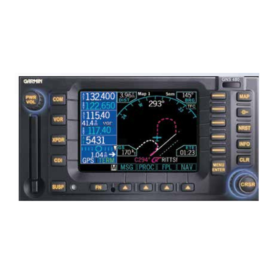
Page 13: Display
Getting Started Display The GNS 480 uses a high-resolution color display to provide information about the different functions. Infor- mation and “smart keys” unique for each mode of operation are displayed. Sample displays with a description of common elements are shown below. When you press the COM, VOR, or XPDR keys on the left side of the display, the window for that function will be outlined and the information active for editing will be highlighted. -
Page 14: Using The Moving Map
Getting Started Using the Moving Map The Map mode provides a moving map for a graphic display of your flight including the surrounding area, as well as navigation information to aid your situational awareness. You can customize each of the four Map pages for the Map range and the information displayed, such as Airports, VORs, NDBs, Intersections, User Waypoints, Airspace, Traffic from TIS or Skywatch, Hi and Lo Airways, Flight Plan course line, or Nav infor- mation items. - Page 15 Getting Started The following symbols are used on the map display to depict active legs of flight, waypoint types, and your aircraft. Turn Left for next flight Airport Ownship - Single plan leg Turn Right for next Ownship - Twin flight plan leg No course change VORTAC...
- Page 16 Getting Started...
- Page 17 Getting Started...
- Page 18 Getting Started...
-
Page 19: Annunciations
Getting Started Annunciations The following annunciations appear on the appropriate displays to provide status or information. All annunciations are available on the moving map display. Annunciations may be output to external annunciators. Annunciation Description Indicates GPS is being used as the navigation source. Appears in lower left corner of the display. VOR/ILS/LOC Indicates VOR/ILS/LOC is being used as the navigation source. - Page 20 Getting Started Message annunciation appears in the lower left corner of the display when a message is available for viewing. A blinking “M” indicates a new message. Vector To Final annunciation appears in the lower left corner of the display when “Vector To Final”...
-
Page 21: Starting Up
Getting Started Starting Up The GNS 480 performs internal checks and shows the status of the tests during start up. The startup screen, owner name (if entered), testing, position, and database information shows on the screen for several seconds and then shows the first Map page. It is not generally necessary to enter a GPS seed position unless the unit has either been moved several hundred miles or been unused for six months or so with the power off. -
Page 22: View Checklists
Getting Started The database information can be checked after start-up in the SW Version page of the System function. Press the Menu/Enter key to continue after you have verified the dates. Valid databases are in green. The database being used has an asterisk (*) next to it, if there are two databases. Expired databases are amber. View Checklists Use a checklist to review preparation for flight. -
Page 23: Using The Remote Transponder
Getting Started Using the Remote Transponder The Transponder Control Mode will allow you to control a compatible remotely mounted transponder from Press XPDR to activate Transponder mode. the GNS 480 front panel. Change the Transponder (Squawk Code) - Two Methods 1. -
Page 24: Nav Terms Diagram
Getting Started Nav Terms Diagram Flight Plan Terms Diagram... -
Page 25: Create A New Flight Plan (Quick Method)
Getting Started Create a New Flight Plan (Quick Method) The Flight Planning function lets you set up and store flight plans where you can name the flight plan, insert a series of waypoints, and then add comments. The Active flight plan is the flight plan that the GNS 480 is currently using for navigation guidance. -
Page 26: Find A Nearest Waypoint
Getting Started Find a Nearest Waypoint The Nearest (NRST) Waypoint Search function allows you to search for the 20 waypoints nearest to your pres- ent position in each of eight waypoints types: Airport, VOR, NDB, INT, User, FSS (Flight Service Station), Air- space, and Air Route Traffic Control Center (ARTCC). -
Page 27: Inserting Terminal Procedures And Approaches . 19 Perform A Raim Prediction
Getting Started Inserting Terminal Procedures and Approaches After creating your flight plan, you can select an approach, departure, or arrival procedure so the GNS 480 can guide you through the flight plan. You may also make adjustments in Flight Edit mode. 1. -
Page 28: Moving Map Mode (Map)
Basic Operation Moving Map Moving Map Mode (MAP) The Map mode provides a moving map for a graphic display of your flight including the surrounding area as well as navigation information. Maps are generally drawn with Ground Track magnetic North at the top of the display (Up). -
Page 29: Moving Map Mode Menu Items
Basic Operation Moving Map Moving Map Mode Menu Items Menu Item Description Airports, VORs, NDBs, Intersections, User Waypoints, Solid reversed label means identifier and location Lo and Hi Airways symbol are displayed. A bold outline means only the location symbol will be displayed. A thin outline means this item will not be displayed on the map. -
Page 30: Gns 480 Map Mode Nav Data Options
Basic Operation Moving Map GNS 480 Map Mode Nav Data Options The following table shows the choices of the options you can make for setting up the Map Mode display in your GNS 480. You can customize the Nav information displayed on the left side of the display for Map Mode pages 2, 3, and 4. - Page 31 Basic Operation Moving Map Selectable Nav Data Fields for Map Pages 2-4 Option Name Abbrev. Description Units Altitude Baro-corrected pressure altitude. Feet (ft) or meters (m) at whole unit Value is dashed out when there is no resolution. valid source. Bearing Bearing to station for the active 0 to 359 degrees at 1-degree resolu-...
-
Page 32: Basic Operation
Basic Operation Moving Map Selectable Nav Data Fields for Map Pages 2-4 Option Name Abbrev. Description Units Estimated Dest ETA The estimated time of arrival to the fi- Hours and minutes, 00:00 to 23:59, Time of nal destination waypoint is based upon based on a 24 hour clock Arrival at Final ground speed. - Page 33 Basic Operation Moving Map Selectable Nav Data Fields for Map Pages 2-4 Option Name Abbrev. Description Units Estimated Fuel Dest FUEL The estimated fuel remaining at the 0.0 to 99999.9 US gallons (usg), Im- Remaining at final destination waypoint using the perial gallons (img), liters (L), pounds Final flight plan information estimated...
- Page 34 Basic Operation Moving Map Selectable Nav Data Fields for Map Pages 2-4 Option Name Abbrev. Description Units Desired Track This is the current DTK to the active 0 to 359 degrees at 1-degree resolu- waypoint. If the current leg is a pilot tion.
- Page 35 Basic Operation Moving Map Selectable Nav Data Fields for Map Pages 2-4 Option Name Abbrev. Description Units Fuel Flow FUEL FLOW Fuel flow is displayed on a per engine 0.0 to 9999.9 US gallons (gph), Impe- rate for twin engines (L and R) or single rial gallons (gph), liters (lph), pounds L or R engine rate (no L or R).
- Page 36 Basic Operation Moving Map Selectable Nav Data Fields for Map Pages 2-4 Option Name Abbrev. Description Units Fuel to FUEL TO Fuel to the next waypoint will be cal- .0 to 99999.9 US gallons (usg), Impe- Waypoint culated given the current fuel flow rate rial gallons (img), liters (L), pounds and the ETE to the waypoint.
- Page 37 Basic Operation Moving Map Selectable Nav Data Fields for Map Pages 2-4 Option Name Abbrev. Description Units Horizontal Fig- HFOM The current 95% confidence horizon- Feet (ft) or meters (m) in whole unit ure of Merit tal accuracy value, as reported by the resolution.
- Page 38 Basic Operation Moving Map Selectable Nav Data Fields for Map Pages 2-4 Option Name Abbrev. Description Units Zulu Time The current system time determined Hours, minutes, and seconds, from GPS if available. Time is dis- 00:00:00 to 23:59:59. played in UTC (Universal Coordinated Time) using the 24-hour clock.
-
Page 39: Nav/Hsi Display (Nav)
Basic Operation NAV / VDI Nav/HSI Display (NAV) The GNS 480 displays a track-based Horizontal Situation Indicator (HSI) view. The Nav function is reached by pressing the NAV smart function key. The layout, annunciations, and nav data are similar to Map mode. Distance to the destination is shown in the top left corner. - Page 40 Basic Operation NAV / VDI The compass rose rotates to align with the track angle of your aircraft at the top. Tick marks are placed every 10 degrees with a larger one every thirty degrees. Small triangles are positioned at 45 degrees to the left and Selecting Displayed Nav Data right of your current track at the top of the compass rose circle as an aid in intercepting courses.
-
Page 41: Panning (Pan)
Basic Operation Panning Panning (PAN) The Panning feature of the Map mode allows you to check out the area near your present position. You can activate the Panning feature by pressing the PAN key or by pressing the CRSR button on the Small knob when in Map mode. -
Page 42: Direct-To
Basic Operation Direct-To Direct-To Press the Direct-To key to get to the Direct-To function which allows you to quickly navigate from your pres- ent position directly to a selected waypoint. You can also use this function to make changes to a flight plan, set up a user-defined holding pattern, sequence directly to a selected leg in your flight plan, and fly a Course To or Course From a selected waypoint. -
Page 43: Inserting A Hold At A Waypoint In The Active Flight Plan
Basic Operation Direct-To Inserting a Hold at a Waypoint in the Active Flight Plan The Hold function of the Direct-To mode prepares you for entering a holding pattern at a waypoint either in your flight plan or from the database. You are limited to one en route holding point at a time. 1. -
Page 44: Course-To (Crsto)
Basic Operation Direct-To 4. Press Menu/Enter to accept the new destination waypoint. Press Menu/Enter again to activate it. By changing the destination, the PROC or FPL Edit modes can be used to load and execute Arrival and/ or Approach procedures to the new destination. This feature replaces the active flight plan with a new one-leg flight plan direct from your present position to the selected destination. -
Page 45: Obs
Basic Operation Direct-To 1. Press Direct-To. Use the Large knob to highlight a waypoint in the active flight plan or press DB and select a new waypoint, if desired, with the Large and Small knobs. 2. Press CrsFr. A map is displayed showing the selected course. 3. -
Page 46: Obs To A Waypoint Not In Your Flight Plan
Basic Operation Direct-To OBS to a Waypoint Not in Your Flight Plan 1. Press Direct-To. Press the DB smart key. 2. Select a new waypoint outside of your flight plan with the Large and Small knobs. 3. Press OBS. Now use the external CDI/HSI resolver to control the selected course. The GNS 480 will read the OBS information and will change the course displayed on the Map displays. -
Page 47: Nearest (Nrst) Search
Basic Operation Nearest Waypoint Nearest (NRST) Search The Nearest Search function allows you to search for the 20 items nearest to your present position in each type. There are eight search types: Airport, VOR, NDB, INT, User, FSS (Flight Service Station), Airspace, and Air Route Traffic Control Center (ARTCC). -
Page 48: Fss And Artcc Frequencies
Basic Operation Nearest Waypoint FSS and ARTCC Frequencies Many FSS and ARTCC locations have multiple frequencies. All frequencies for each FSS or ARTCC may be viewed by turning the Small knob. You can quickly insert the frequencies into the Com radio. Press <-SBY to insert the highlighted frequency into the Standby position or <-A->... -
Page 49: Using The Nrst Function To Change Your Destination To A Nearest Airport
Basic Operation Nearest Waypoint Using the NRST Function to Change Your Destination to a Nearest Airport 1. Press NRST. 2. Turn the Large knob to select the desired nearest airport. 3. Press the INFO key. Note, if “IFR” is listed with the identifier, instrument approaches are available. Press INFO again to toggle back to the Nearest Waypoint list. -
Page 50: Information On Waypoints (Info)
Basic Operation Info Information on Waypoints (INFO) Info mode allows you to view information about the selected waypoint. Examples of selecting a waypoint can be: highlighted waypoint in the flight plan, waypoint selected from Nearest Waypoint list, waypoint selected in Pan mode, or a waypoint selected from the database. The WGS-84 map datum is noted as W84. Other map datums are noted as unknown (unk). -
Page 51: Airport Frequency Information
Basic Operation Info Info Mode - Frequency Information Info Mode - Airport Information Press the Freq key for frequency details Airport Frequency Information Additional information is available for Airport Frequencies that have an asterisk (*) by the frequency type. 1. Turn the Large knob to highlight the desired frequency. Frequencies with an asterisk will have more information available. -
Page 52: Vor Information
Basic Operation Info VOR Information • Identifier, city, state, country, bearing and distance (GPS-determined distance) from present position, frequency, lat/lon coordinates, and station declination at the VOR. • Map of area Info Mode - VOR Information NDB Information • Identifier, city, state, country, bearing and distance from present position, frequency, lat/lon coordinates, and magnetic variation. -
Page 53: Raim Prediction
Basic Operation Info RAIM Prediction Receiver Autonomous Integrity Monitoring (RAIM) is a method of predicting possible system accuracy errors that may be caused by bad satellite data. The RAIM algorithm requires that more satellites are available and usable than is required for a normal GPS position fix. RAIM prediction is used when you are operating outside of areas served by WAAS coverage or if WAAS is unavailable. -
Page 54: Com Radio (Com)
Basic Operation Com Radio Com Radio (COM) Press COM to activate control of the internal Com Radio. Pressing COM again returns you to the previous mode. All other functions will continue to function normally, such as navigation of active flight plans. Turn the PWR/VOL knob to control the Com volume. -
Page 55: User
Basic Operation Com Radio User The Com radio will store up to 25 User-saved frequencies. The Com and Nav User lists are separate sets of 25. 1. Press the User key to bring up a list of User frequencies. 2. Turn the Large knob to highlight a frequency. 3. -
Page 56: Audio
Basic Operation Com Radio Audio The Audio function allows you to control audio levels of the Com radio. The AMA setting adjusts the volume level of the message tones. The Com setting adjusts the Com radio audio level. The Sidetone setting adjusts the feedback level from the microphone into the headset headphone. -
Page 57: Nav Radio (Vor)
Basic Operation Nav Radio Nav Radio (VOR) Press VOR to activate control of the internal Nav Radio. All other functions will continue to function normally, such as navigation on active flight plans. DME Distance Distances, such as to a Localizer/DME waypoint (equivalent to Localizer DME), are based on calculated distances from GPS information. -
Page 58: Recall (Rcl)
Basic Operation Nav Radio Recall (RCL) 1. Press the RCL key to bring up a list of the last eight VOR/ILS frequencies used as the Active frequency. 2. Turn the Large knob to highlight a frequency. 3. Press the <SBY or <A> keys to insert the frequency. 4. -
Page 59: Test Log
Basic Operation Nav Radio Test Log The Test Log function allows you to store information about the last time you tested your Nav receiver. The information you can enter includes: Date (month, day, year), Type of test (Differential, Ground, Air), Location (text), Bearing Error (-5 to +5), and name of person logging the test information (text). -
Page 60: Transponder Control (Xpdr)
Basic Operation XPDR Transponder Control (XPDR) If a remote compatible transponder is connected and setup to operate with the GNS 480, the Transponder Control Mode will allow you to control your transponder from the GNS 480 front panel. Some features are common to the available transponders and are explained below. -
Page 61: Vfr
Basic Operation XPDR Press the VFR key to select the VOR 1200 squawk code. This value can be set in the System Configuration mode. This menu item is available when used with the SL70, SL70R, GTX 32, GTX 327, GTX 33, and GTX 330. -
Page 62: Ground
Basic Operation XPDR 2. Turn the Small knob to change characters. Turn the Large knob to move to the next character. Press the CLR key to delete a character. 3. Press the Menu/Enter key to end editing and save the values. Ground When the Ground selection is pressed the GTX 33 or 330 will be placed in Ground mode where the transpon- der operation will operate normally except no Mode A or C replies are allowed. -
Page 63: Flight Planning (Fpl)
Basic Operation Flight Planning Flight Planning (FPL) The Flight Planning function lets you set up and store flight plans where you can name the flight plan, insert a series of waypoints, airway segments, departure, arrival, and approach procedures, add comments, save the plan, and execute it. -
Page 64: Library Flight Plan
Basic Operation Flight Planning Library Flight Plan The flight plan Library contains up to 50 flight plans you have created and saved. With a Library flight plan highlighted, the menu items are: Execute, Comment (Cmnt), Copy, or Edit. When you Execute (EXEC) a flight plan from the Library, you select a flight plan by scrolling through the Library list with the Large knob and press EXEC. -
Page 65: Cross Link (X-Link)
Basic Operation Flight Planning Cross Link (X-Link) Two GNS 480’ s can be connected and set up during installation to work together. Flight plans and User waypoints are shared. Pressing the SUSP key on either unit will suspend waypoint sequencing on both units. When the X-Link function is activated, the units will share control of the active flight plan. -
Page 66: Edit
Basic Operation Flight Planning Edit Pressing the Edit menu item key, while highlighting the Active flight plan, creates a copy of the active flight plan, which is called the “Modified” flight plan. Making a copy protects you from accidently changing your ac- tive flight plan. -
Page 67: Discontinuity
Basic Operation Flight Planning Discontinuity A Discontinuity is a message placed in the affected position in a flight plan indicating the GNS 480 needs to know how you want to go between the two waypoints. Discontinuities are also inserted into the flight plan when a standard instrument departure (SID) does not match the first waypoint in the en route section of the flight plan or when STAR or approach end points do not match or when a STAR terminating waypoint does not match the IAF of the approach. -
Page 68: Searching For Waypoints To Insert Into A Flight Plan
Basic Operation Flight Planning Searching for Waypoints to Insert into a Flight Plan The following steps describe in general how you can select a waypoint for one of the points in a flight plan. 1. Press the FN key (if necessary) and then the FPL key. 2. -
Page 69: Activate A Flight Plan
Basic Operation Flight Planning Activate a Flight Plan 1. Press the FPL function smart key to display the Flight Plan library. If the active flight plan is displayed, press the BACK function smart key. 2. Turn the Large knob to the desired active flight plan. 3. -
Page 70: Deleting A Waypoint Or Airway In Your Flight Plan
Basic Operation Flight Planning Deleting a Waypoint or Airway in Your Flight Plan 1. While editing your flight plan, turn the Large knob to highlight the waypoint or airway, in the compressed view (XPND is not highlighted), you want to delete. 2. -
Page 71: Set Origin, Destination, And Alternate Waypoints
Basic Operation Flight Planning Take off A. Set Origin, Destination, and Alternate Waypoints. B. Add Standard Instrument Departure Procedure (SID), if required. C. Insert en route flight plan of Airways and/or Waypoints. En Route D. Modifying a Flight Plan While in Flight Approach and Landing E. -
Page 72: Insert En Route Flight Plan Airways And/Or Waypoints
Basic Operation Flight Planning 4. The runway is highlighted. Use the Small knob or menu item keys on the right side of the display to select a runway. 5. Turn the Large knob to select the departure procedure and transition. 6. -
Page 73: Add Arrival Procedures (Stars)
Basic Operation Flight Planning Selecting an Alternate Airport 1. Press FN and then PROC to go to the Procedure Mode. Flying Direct to a Waypoint in a 2. Press the Select key next to the Alternate airport. Flight Plan 3. Next, press the Load key to load the alternate to the destination airport into your flight plan. \ 1. -
Page 74: Leg Types
Basic Operation Flight Planning LEG TYPES The GNS 480 is the only panel mount navigator to implement all the available leg types that currently exist in airways, instrument proce- dures, and approaches. These legs are described in the following diagrams, with associated descriptions of each leg. Because the GNS 480 supports these leg types, it automatically sequences through the majority of the flight plan legs, or allows for a simple one keystroke interface to sequence when automatic sequencing is not available. - Page 75 Basic Operation Flight Planning Leg Types Flight Plan Page Active From/To/Next Waypoints Description (PILOT NAV) The heading to a radial leg defines a heading to fly and a VOR radial at which the leg terminates. The VOR radial is defined by both the VOR identifier and the radial number.
- Page 76 Basic Operation Flight Planning Leg Types Flight Plan Page Active From/To/Next Waypoints Description The heading to a manual termination leg defines a heading to fly until the pilot initiates sequencing. Like the fix to a manual termination leg, this type of leg is most often used where the pilot is to expect vectors from air traffic control.
- Page 77 Basic Operation Flight Planning Leg Types Flight Plan Page Active From/To/Next Waypoints Description The course to an altitude leg defines a specific course to be flown from the position at which the leg is initiated and an altitude at which the leg terminates. Sequencing occurs auto- matically upon reaching the specified altitude.
- Page 78 Basic Operation Flight Planning Leg Types Flight Plan Page Active From/To/Next Waypoints Description (PILOT NAV) The course to a radial leg defines a specific course to be flown from the position at which the leg is initi- ated and a VOR radial at which the leg terminates. The VOR radial is defined by both the VOR identifier and the radial number.
- Page 79 Basic Operation Flight Planning Leg Types Flight Plan Page Active From/To/Next Waypoints Description The initial fix defines a database fix to be used in the flight plan, not an actual leg. The fix will serve to define the begin- ning of a leg that follows such as a track to fix or course from fix leg.
- Page 80 Basic Operation Flight Planning Leg Types Flight Plan Page Active From/To/Next Waypoints Description The hold to a fix leg defines a holding pattern that is to be flown only once. This leg is most often used in newer RNAV procedures in place of a procedure turn to accomplish a course reversal.
- Page 81 Basic Operation Flight Planning Leg Types Flight Plan Page Active From/To/Next Waypoints Description (PILOT NAV) The fix to an altitude leg defines a specific course to be flown away from a database fix and an altitude at which the leg terminates. The pilot will have to maintain the desired course manually and initiate sequencing manually upon reach- ing the specified altitude.
- Page 82 Basic Operation Flight Planning Leg Types Flight Plan Page Active From/To/Next Waypoints Description The fix to a manual termination leg defines a specific course to be flown away from a database fix to an unspecified location. This type of leg is most often used where the pilot is to expect vectors from air traffic control, for example, at the end of an ar- rival.
-
Page 83: Procedures
Basic Operation Procedures Procedures The Procedure mode allows you to add or modify procedures to standard locations within the active flight plan. No options will be available if there is not an active flight plan. When you start adding or modifying procedures, a modified (copy of the active) flight plan is created. -
Page 84: Steps For Approach Operations
Basic Operation Procedures Basic Approach Operations Examples The GNS 480 provides precision and non-precision approach guidance using its built-in GPS receiver. The Steps for approach operations moving map pages can also be used as a supplemental aid to situational awareness for ILS approaches (and •... -
Page 85: Approaches With Procedure Turns
Basic Operation Procedures Approaches with Procedure Turns Lynchburg (VA) Regional The procedure turn portion of an approach is stored VOR or GPS Rwy 04 as one of the legs of the approach. For this reason, the GNS 480 requires no special operations from the pilot —... -
Page 86: Flying The Procedure Turn
Basic Operation Procedures Flying the Procedure Turn 1. Within 30 nautical miles of the destination airport, the GNS 480 switches from “en route” mode to “terminal” mode (as indicated in the lower left corner of the screen). The switch to terminal mode ... - Page 87 Basic Operation Procedures Within 2.0 nautical miles of the FAF (LYH), the GNS 480 switches DO NOT from terminal mode to “approach” mode. CDI scaling is tightened USE FOR from either 2° or 1.0 to 0.3 nautical miles, full scale deflection, NAVIGATION RW04 whichever is smaller.
-
Page 88: Flying The Missed Approach
Basic Operation Procedures Flying the Missed Approach After you pass the MAP, if you cannot continue the approach and land, usually you must execute a missed approach. The GNS 480 will automatically sequence to the first leg of the missed approach. Fly the heading ... -
Page 89: Flying An Approach With A Hold
Basic Operation Procedures Flying an Approach with a Hold Starting where the previous example left off, we’ll assume weather conditions resulted in a missed approach at Lynchburg Regional. Now, you’ve decided to divert to Farmville Regional (KFVX) instead. If KFVX is nearby, ... - Page 90 Basic Operation Procedures 7. Just prior to crossing the BODRY intersection, a message — ”HOLD TEARDROP” — appears on the bottom of the screen to suggest the proper holding pattern entry. “HOLD DIRECT AHEAD” or “HOLD TEARDROP AHEAD” may be offered on other similar approaches.
- Page 91 Basic Operation Procedures NOTE: When viewing the Map Page, you’ll note that the final course segment is displayed in magenta — the active leg of the flight plan always appears in magenta. 12. As you approach the MAP, a waypoint message (“NEXT TRACK 212°”) appears in the lower right ...
-
Page 92: Flying A Dme Arc Approach
Basic Operation Procedures Flying a DME Arc Approach The VOR DME arc approach uses additional Jeppesen-provided waypoints to define the arc. These waypoints are indicated by “D” as the first letter in the waypoint name. This is followed by three numbers indicating the radial the waypoint lies on. - Page 93 Basic Operation Procedures 3. Within 30 nautical miles of KTOP, the DO NOT USE FOR DMARY GNS 480 switches from en route mode NAVIGATION to terminal mode and the CDI scale transitions from 2.0 to 1.0 nautical miles, full scale deflection.
- Page 94 Basic Operation Procedures 8. As you approach the FAF, a waypoint DO NOT USE FOR message (“RIGHT TO TRK 214°”) on the NAVIGATION bottom of the screen appears. As this is not a GPS overlay, press the CDI key to switch from the GPS to the VOR source for the CDI.
-
Page 95: Vectors To Final
Basic Operation Procedures Vectors To Final Let’ s take a second look at the “VOR 22” approach into Billard Municipal (KTOP). Instead of following the When you are in the Terminal area, you DME arc, ATC tells you to expect vectors onto the final approach course. There are several ways to select may be directed to fly a vector to final “vectors to final”... -
Page 96: Flying A Vectored Approach
Basic Operation Procedures Flying a Vectored Approach DO NOT USE FOR With “Vectors-To-Final” selected, the CDI needle NAVIGATION remains off center until you’re established on the final approach course. The Map Page displays an extension of the final approach course in magenta (remember, ma- genta is used to depict the active leg of the flight plan) and “VTF”... - Page 97 Basic Operation Procedures 6. As the CDI needle centers, make any remaining course corrections to establish yourself on the final approach course. 7. As you approach the FAF, a waypoint alert on the bottom of the screen (“RIGHT TO TRK 214°”) appears. Make ...
-
Page 98: Ils Approaches
Basic Operation Procedures ILS Approaches Precision approaches can be performed with the GNS 480’ s built-in VLOC (VOR/localizer/glideslope) receivers. The GPS receiver can be used for guidance prior to reaching the final approach fix, but once there, the proper frequency must be selected on the VLOC window (left side of screen) and the CDI output set to “VLOC”. The GNS 480 can be set to automatically switch the external CDI output from GPS to VLOC as you inter- cept the final approach course. -
Page 99: Selecting An Ils Approach
Basic Operation Procedures Selecting an ILS Approach Flagstaff (AZ) Pulliam For this example, we’ll use a flight ILS DME Rwy 21 from Laughlin Bullhead (Arizona) International to Flagstaff Pulliam (KFLG) and select the ILS runway 21 approach. “SHUTR” intersec- tion is selected as the IAF, which includes an outbound leg and a ... -
Page 100: Flying The Ils Approach
Basic Operation Procedures Flying the ILS Approach When you “Execute” an ILS approach, automatic switching of the external CDI is enabled (unless turned off from the CDI/Alarms line on the System- Configuration Page). When you are established on the ... - Page 101 Basic Operation Procedures 7. Turn right to a heading of 075° to initiate the procedure turn. The external CDI needle starts moving to the left. For roll steering-capable autopilots, you may select the in bound course (210°) and let the GNS 480 fly the procedure turn automatically.
- Page 102 Basic Operation Procedures 11. Also as you approach SHUTR, a waypoint DO NOT USE FOR message (“NEXT TO TRK 210°”) appears on NAVIGATION the bottom of the screen. 12. As you cross SHUTR, the destination sequences to the MAP (“RW21”, the runway threshold).
- Page 103 Basic Operation Procedures 16. The GNS 480 will automatically sequence upon reaching the required altitude Direct-To FLG for the missed approach hold. Continue to fly the CDI needle guidance and the missed approach hold, as described earlier.
-
Page 104: Selecting An Lpv Approach
Basic Operation Procedures Selecting an LPV Approach For this example, we’ll use a flight from Eugene Oregon (KEUG) to Salem Oregon (KSLE) and select the RNAV runway 31 approach. “GLORR” intersection is selected as the IAF. Of course, vectors-to-final could also be selected, as previously described for the non-precision approach examples. -
Page 105: Flying The Lp Approach
Basic Operation Procedures 6. When LOTKE (the FAF) becomes the active waypoint, the glideslope flag will be removed and the glideslope will become active. Capture the glideslope as you would an ILS glideslope. 7. As you cross LOTKE, the destination sequences to the MAP (“RW31”, the runway threshold). With the needle on the external CDI (or HSI) centered, fly toward the MAP, observing the altitude minimums dictated by the approach plate. - Page 106 Basic Operation Procedures 4. As you approach the FAF, the GNS 480 will begin to automatically rescale in an angular fashion. This will allow the LP approach to be flown in the same fashion as a standard localizer approach. At 2.0 nautical miles from the FAF, CDI scaling is tightened from either 2°...
-
Page 107: Rnav Approach Procedures
Basic Operation Procedures RNAV APPROACH PROCEDURES The GNS 480 allows for flying LNAV, LNAV/VNAV, LNAV with advisory vertical guidance (annunci- ated as LNAV +V), LP, LP with advisory vertical guidance (annunciated as LP +V), and LPV approaches according to the published charts. Description Minimums Annunciation... - Page 108 Basic Operation Procedures Localizer Performance with Vertical guid- Published LPV minimums. ance (LPV) approach. RNAV precision approach. LP indicates Localizer Performance with Published LP minimums. no vertical guidance. LP +V LP +V indicates Localizer Performance Published LP minimums. with advisory vertical guidance. This advi- sory guidance follows the same nature as set by the LNAV +V as shown above.
- Page 109 Basic Operation Procedures on the bottom left of the screen). “SUSP” indicates that automatic sequencing of approach waypoints is suspended on the current leg and normally appears at holding patterns or upon reaching a Pilot Nav Leg. • For roll steering autopilots: roll steering is terminated when approach mode is selected on the autopilot and is available after passing the MAP.
- Page 110 Basic Operation Procedures • When an ILS or VOR approach is first selected or executed, the frequency is automatically checked, if correct. If the frequency is correct, you will not receive a message regarding the frequency. If the frequency is incorrect, you will receive a message and you must place the ILS frequency in the active frequency field by pressing the Menu/Enter key when the frequency mes- sage is received.
-
Page 111: Timers (Tmr)
Basic Operation Timers Timers (TMR) The Timer Mode allows you to set or view several timing functions. You can set one or two timers as count up or count down timers. You can view the Trip Time, Trip Distance, Flight Time, and Flight Distance. The Trip Time and Trip Distance show the time and distance traveled since being reset. -
Page 112: Flight Time And Distance
Basic Operation Timers Flight Time and Distance The Flight Time and Distance counters start and stop according to two rules: 1) The counters reset and start once the aircraft goes above the Trigger Speed for ten seconds. 2) The counters stop after the aircraft has been below the Trigger Speed for 30 seconds or more. Trigger Speed Set the Trigger Speed for the speed where you want the Flight Time and Distance counters to start and stop. -
Page 113: Checklist (Chk)
Basic Operation Checklist Checklist (CHK) The Checklist function allows you to create up to eight checklists with up to 100 items in each list. You can use this feature as a method to create customized checklists for in-cockpit review. Creating a New or Editing an Existing Checklist 1. -
Page 114: Move A Checklist
Basic Operation Checklist Move a Checklist 1. Press FN and then the CHK key to start the Checklist function. 2. Press the MOV key. 3. Turn the Large knob to the position in the order of lists where you want to put the highlighted list and press the Menu/Enter key. - Page 115 Basic Operation Checklist Checklist Items Altimeter &, Altimeters Annunciator Lights Instruments Approach Briefing Auto Ignition Autopilot Battery Switch Bleed Air Valves Cabin Door Light Cabin Temp Mode Cabin Circuit Breakers Control Lock Cowl Flaps Crossfeed Valve Electric Trim Engine Instruments Environmental System Flaps Flight Controls...
- Page 116 Basic Operation Checklist Checklist Results AS REQD AUTO CHECK BOTH CHECK ON CHECKED CHECKED AS REQD CHECKED OFF CHECKED OUT CHECKED SET COMPLETE CUT-OFF DOWN EXCERCISED FEATHER FREE CORRECT FULL RICH HI RPM IDLE LO IDLE LOW RPM NORMAL NS/FSB OFF AS REQD ON CHECKED OPEN...
-
Page 117: User Waypoints (User)
Basic Operation User Waypoints User Waypoints (USER) The GNS 480 can hold up to 500 user-defined waypoints. These waypoints can be based on either lat/lon posi- tion or range and bearing from a reference point. In the User Waypoint function, you can create new waypoint, edit existing ones, or search for a User waypoint. -
Page 118: System Mode (Sys)
Current database versions are shown in green. Out of date database versions are shown in yellow. This information is useful should you need to talk with Technical Support at Garmin. Please copy the values for the information on this display before calling Garmin Product Support (913) 397-3200. -
Page 119: Configuration
Basic Operation Configuration The Configuration page lets you customize many of the settings and unit measurements for your installation or local needs. 1. Press FN and then the CNFG key to reach the Configuration functions. 2. Turn the Large knob to highlight the value you want to change. The green arrow on the right side of the display indicates the direction to turn the Large knob to view more choices. -
Page 120: Magnetic Variation Selection
Basic Operation System Magnetic Variation Selection You may choose either automatic or manual magnetic variation selection. When navigation information needs to be referenced to True North, manually set magnetic variation to zero. 1. Turn the Large knob to highlight the Mag Var selection. 2. -
Page 121: Ils Cdi
Basic Operation System ILS CDI Switching the CDI from GPS to ILS for ILS approaches can be set to either Auto or manual. The Auto setting allows the CDI output to automatically switch from the GPS receiver to the LOC receiver during ILS or LOC approaches. -
Page 122: Fuel Type
Basic Operation System Fuel Type This selection allows you to choose the type of fuel for your reference. Choices are: Avgas, Jet A, or JP4. 1. Turn the Large knob to highlight the Fuel Type selection. 2. Press the CRSR knob in to start editing. 3. -
Page 123: Fuel Low Message
Basic Operation System Fuel Low Message Set the time for an alert that will appear a specified time prior to fuel being exhausted based on fuel remaining and the current fuel consumption rate. Time is selectable between 0 and 59 minutes. 1. -
Page 124: Minimum Brightness Value
Basic Operation System Minimum Brightness Value When the Display Brightness selection is set to Automatic, the Minimum Brightness value can be set between 0.20 and 130.00 foot-lamberts of light. 1. Turn the Large knob to highlight the Minimum Brightness selection. 2. -
Page 125: Owner Information
Basic Operation System Owner Information The Owner Information selection allows you to enter up to two rows of information about the owner or aircraft. 1. Turn the Large knob to highlight the Owner Name selection. 2. Press Menu/Enter key to start editing the Owner information. 3. -
Page 126: Enable Sbas Providers
Basic Operation System Enable SBAS Providers Normally the best selection of satellites for SBAS coverage is automatically selected. You may manually enable or disable specific SBAS providers. Normally all SBAS providers should be enabled, but there may be some situations where it may be useful to disable an SBAS provider or when required by local regulatory agencies. 1. -
Page 127: Parallel Track (Ptk)
Basic Operation Parallel Track Parallel Track (PTK) The Parallel Track (PTK) function allows you to create a parallel course offset of 1 to 99 NM to the left or right of your current flight plan. You must have FROM and TO waypoints defined. Parallel Track cannot be activated if you set a course using Direct-To or if the active leg is the first leg of the departure procedure, or the Initial Ap- proach Fix (IAF) has been passed. - Page 128 Basic Operation Parallel Track When Parallel Track is Activated, “p” is added to the waypoint names in the “From-To-Next” line at the bottom of the map and on the waypoints shown on the map. The PTK annunciator is shown in the left corner of the screen. Parallel Track Description...
-
Page 129: Simulator Mode
Basic Operation Simulator Simulator Mode The GNS 480 has a built-in simulator so you can practice with your unit without being in flight. You can set your present position, ground speed, and track. The track can also be set to Auto to simulate use with an auto- pilot. -
Page 130: Present Position (Ppos)
Basic Operation Simulator Present Position (PPOS) Press the PPOS key to bring up a display for selecting a Lat/Lon position for your ownship starting point. 1. Turn the Large knob to select the item to change. 2. Turn the Small knob to change the values. 3. -
Page 131: Messages (Msg)
Basic Operation Messages Messages (MSG) Message mode lets the pilot know about conditions that require immediate attention. Depending on the level of importance, a message box may appear on the display over the active mode. A flashing annunciator “M” will appear at the bottom of the display when a message is available for viewing. - Page 132 Basic Operation Messages Message Description Parallel Track Ending within x minutes/x seconds Pilot awareness of upcoming pilot action required. CAUTION Communications lost with cross-linked unit Communications have failed between the reporting and an external GNS 480. CAUTION Communications lost with Com Radio Communications have failed between the GNS 480 and its Com radio CAUTION Stuck Microphone...
- Page 133 Basic Operation Messages Message Description Database Invalid: Integrity check failed Check to see if card is seated properly. Replace datacard if necessary. Using Manual Mag Var: <deg>×<E or W> User may have set Mag Var to manual. If received with Database Invalid message, see above.
- Page 134 Basic Operation Messages Message Description WARNING Loss of Integrity Cross-Check NAV GPS position integrity lost. Verify by cross-checking with VHF Nav. Integrity Restored Normal Ops Pilot awareness. WARNING Loss of Navigation - Insufficient Sats GPS position lost. Use other Nav equipment. WARNING Loss of Navigation - Position Error GPS position lost.
- Page 135 Basic Operation Messages Message Description Baro Correction xx.yy CRSR to Change, ENTER to Input correct baro setting. Accept WARNING Loss of Navigation Abort Approach Execute missed approach using other nav equipment. WARNING CO Level Alarm CO Guardian has issued this alarm. No valid OBS input detected.
-
Page 136: Audio Messages
Basic Operation Messages Audio Messages The GNS 480 provides audio messages, as well as text. A tone accompanies every new text message. The tone is a short “ding” that lasts less than one second. Message tones will not be generated for messages already in the message list. -
Page 137: Traffic (Tfc)
Basic Operation Traffic Traffic (TFC) The GNS 480 displays traffic when the GTX 33/330 Transponder or Skywatch system are configured with the GNS 480. When available, the Traffic function is reached by pressing the FN key and then the TFC function smart key. -
Page 138: Traffic Pop-Up
Basic Operation Traffic Traffic Pop-Up A small Traffic window will “Pop-Up” when a Traffic Advisory (TA) occurs. The Traffic Pop-Up will appear over any existing display except for the Traffic mode display. The default pop-up has a range of 6 NM/2 NM. When the Traffic Pop-Up appears you can: •... -
Page 139: Vertical Display Modes
Basic Operation Vertical Display Modes The Vertical Display Mode selection is available only when Skywatch is installed. When selected, the display of Vertical information can be selected as Normal (NRM), Look Down (Below - BLW), Unrestricted (UNR), or Loop Up (Above - ABV) as described in the Skywatch documentation. The display mode refers to the altitude range relative to your altitude for reporting traffic. -
Page 140: Traffic In Map Mode
Basic Operation Traffic Traffic in Map Mode Traffic may be viewed on any of the Map mode displays by pressing the Traffic display Menu Item selection in Map mode. Traffic Annunciations Interruption of information from the traffic sensor will be reported on the GNS 480 display by an annunciation on the Map and Traffic mode pages. -
Page 141: Specifications
Appendix GPS Performance Receiver: 15 parallel channel receiver (12 GPS and 3 GPS/WAAS/SBAS) Specifications Acquisition Times: Approx. 10 seconds (reacquisition) Approx. 1:45 minutes TTFF (Time To First Fix)) Update Rate: 0.2 per second (5 Hz), continuous Physical Specifications Size: 6.25” W x 3.3” H x 11.7” D GPS Accuracy: <... -
Page 142: Care Information
DO NOT use any chemical cleaning agents. Care should be taken to avoid scratching the surface of the display. To resolve problems that cannot be remedied using this guide, contact Garmin Product Support in the U.S.A. at 866/739.5687 or Garmin Europe at 44/ 0 87 0850 1243. -
Page 143: Garmin Data Cards
Installing and Removing Data Cards The GNS 480 uses an optional Garmin data card to display digital charts and maps on-screen or save user data. Install the data card in the card slots located on the left side of the unit. Install or remove the data card only when the unit is off. -
Page 144: Contacting The Factory
Appendix If the GNS 480 unit fails to operate despite troubleshooting efforts, contact Garmin Technical Support for Contacting the Factory assistance. GARMIN International, Inc. 1200 East 151st Street Olathe, KS 66062-3426 Phone: (913) 397-8200 FAX: (913) 397-8282 http://www.garmin.com Be prepared to offer the following information about the installation: •... -
Page 145: Glossary
Appendix Accuracy— Estimated position accuracy in feet or meters. Altitude—Height above mean sea level (MSL). Glossary Backcourse— Localizer backcourse approach where the signal on the “back” side of the localizer is used for alignment to the runway opposite of normal localizer alignment. Without compensation the CDI would reverse sense. - Page 146 Appendix the next waypoint in a route. Elevation— The altitude (height) above or below sea level. Flight Timer—The length of time for the current flight. Fuel Timer—The fuel required to travel from current location to the indicated route waypoint. Glide Ratio—The ratio of horizontal distance travelled to vertical distance travelled. For example, a 6:1 glide ratio indicates a 1000’...
- Page 147 Appendix Squitter— Mode S transmissions without the need for being interrogated. Sunrise—The time at which the sun rises on this day. Sunset—The time at which the sun sets on this day. Time—The time for the selected time zone. Track— The direction of movement relative to a ground position. Also referred to as ‘ground track’. Trip Avg Speed (Moving)—...
- Page 148 Appendix Abbreviations DA — Decision Altitude The following is a list of abbreviations and °C — Degrees Celsius DB — Database acronyms used on the GNS 480 and their mean- CAS — Calibrated Airspeed DEST — Destination ings: CCW — Counter-Clockwise DH —...
- Page 149 Appendix ETE — Estimated Time En Route kph — Kilometers Per Hour HDG — Heading kt — Knots °F — Degrees Fahrenheit HFOM — Horizontal Figure Of Merit FADC — Fuel/Air Data Computer hg — Inches of Mercury LAT/LON — Latitude/Longitude FAF —...
- Page 150 Appendix °M — Degrees Magnetic RMVD — Removed NDB — Non-Directional Radio Beacon m — Meters RNAV — Area Navigation nm — Nautical Miles mb — Millibars of Pressure RNG — Range NoPT — No Procedure Turn Required MDA — Minimum Decision Altitude NRM —...
- Page 151 Appendix Suspended usg — US gallons WPT — Waypoint SYS — System UTC — Coordinated Universal Time WX — Weather (also GMT or “zulu”) XPDR — Transponder VDI — Vertical Deviation Indicator °T — Degrees True XPND — Transponder VERS — Version TACAN —...
-
Page 152: Waas
Keep used battery away from children. Do not disassemble and do not dispose of in fire. WARNING: Only replace with Garmin Lithium-Ion Battery Pack (Garmin Part Number 010-10517-00). Use of another battery may present a risk of fire or explosion. -
Page 153: Compliance, License, And Warranty Information
The GNS 480 does not contain any user-serviceable parts. Repairs should only be made by an authorized Garmin service center. Unauthorized repairs or modifications could result in permanent damage to the equip- ment, and void your warranty and your authority to operate this device under Part 15 regulations. -
Page 154: Canadian Rf Exposure And Compliance
Appendix Canadian RF Exposure and Compliance To ensure compliance with the RF exposure limits of Industry Canada specification RSS-102 while using the Compliance, License, and Com transmitter, the operating limitations below must be observed, unless an installation-specific evaluation Warranty Information has been performed according to the requirements of RSS-102. -
Page 155: Software License Agreement
LOWING SOFTWARE LICENSE AGREEMENT. PLEASE READ THIS AGREEMENT CAREFULLY. Warranty Information Garmin grants you a limited license to use the software embedded in this device (the “Software”) in binary ex- ecutable form in the normal operation of the product. Title, ownership rights, and intellectual property rights Serial Number in and to the Software remain in Garmin. -
Page 156: Limited Warranty
(iv) damage caused by service performed by anyone who is not an authorized service provider of Garmin; or (v) damage to a product that has been modified or altered without the written permission of Garmin. -
Page 157: Index
Index Index Audio Level 48, 50, 128 Controls 2 Audio Messages 128 Copy 58 FCC Compliance 145 Auto-Switch 90, 93, 94, 101, 113 Course 137 Flight Distance 104 Automatic Track Course-From 36 Flight ID 53 Simulator 121 Course-To 36 Flight Legs 66 Abbreviations 140, 141, 142 Cross Link 57 Flight Plan 55... - Page 158 Index Serial Number 147 Signal 47 Helipad 41 Magnetic Variation 112 OBS 37 Simulator 121 Hold 35 Manual Track Owner Information 117 Skywatch 130 HPL 12, 32, 110, 141 Simulator 121 Slave 121 HSI 31 Master 121 Pan Mode 33 Software Version 110 Menu/Enter 4 Range 33...
- Page 159 Index Turn 139 Turn Short Path 66 X-Link 57 XPDR 52 User Frequencies 47 User Waypoints 33, 109 Vectors 87 Vector to Final 75, 80, 87 Velocity Made Good 139 Vertical Speed 139 VFR Squawk 117 VOR 44 VPL 12, 32, 110, 143 WAAS 118, 144 Wide Area Augmentation System Warranty 148...
- Page 160 This page intentionally left blank...
- Page 162 Street, Olathe, Kansas 66062, U.S.A. Garmin (Europe) Ltd. Liberty House, Bulls Copse Road, Hounsdown Business Park, Southhampton, SO40 9LR, U.K. Garmin Corporation (Singapore) 46 East Coast Road, #05-06 Eastgate, Singapore 428766 www.garmin.com Garmin AT Part Number 560-0984-01 Rev. G (Garmin P/N 190-00502-00 Rev D)
Need help?
Do you have a question about the CNX 80 and is the answer not in the manual?
Questions and answers