Table of Contents
Advertisement
Quick Links
Advertisement
Table of Contents

Related Manuals for SIGLENT TECHNOLOGIES SDG7000A Series


Summary of Contents for SIGLENT TECHNOLOGIES SDG7000A Series
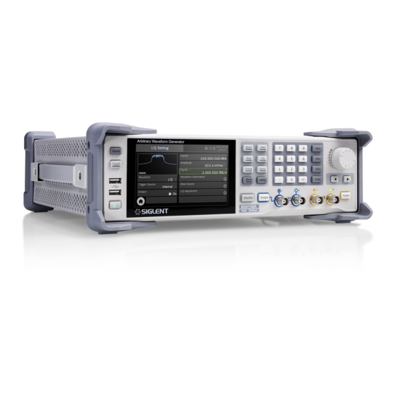
- Page 1 SDG7000A Series Arbitrary Waveform Generator User Manual EN01A...
- Page 2 Copyright SIGLENT TECHNOLOGIES CO., LTD. All Rights Reserved. Trademark Information SIGLENT is the registered trademark of SIGLENT TECHNOLOGIES CO., LTD. Declaration SIGLENT products are protected by patent law in and outside of P.R.C. SIGLENT reserves the right to modify or change parts of or all the specifications or pricing policies at company’s sole decision.
-
Page 3: Table Of Contents
SDG7000A User Manual CONTENT INTRODUCTION ........................1 IMPORTANT SAFETY INFORMATION ..................2 ........................... 2 ENERAL AFETY UMMARY ........................4 AFETY ERMS AND YMBOLS ..........................4 ORKING NVIRONMENT ..........................6 OOLING EQUIREMENTS ....................6 OWER AND ROUNDING EQUIREMENTS ................................. 7 LEANING .............................. - Page 4 SDG7000A User Manual 6.3.7 Trigger in/Trigger out/Synchronous out ................22 6.3.8 External modulation signal/counter input ................22 6.3.9 Marker output ........................22 6.3.10 Digital signal output ......................22 TOUCH SCREEN DISPLAY ....................23 ..............................23 ........................... 24 ARAMETER ETTING ....................25 ESCRIPTION OF CONS IN THE TATUS...
- Page 5 SDG7000A User Manual 11.3 W ........................... 89 AVEFORM OMBINE 11.4 C ....................... 90 HANNEL RACKING OUPLING 12 OUTPUT SETTINGS ....................... 92 12.1 O ..............................92 VERVIEW 12.2 P ................................ 93 OLARITY 12.3 N ..............................93 OISE 12.4 A ............................94 MPLITUDE IMIT 12.5 D...
- Page 6 SDG7000A User Manual 16.8 H ................................120 17 REMOTE CONTROL ......................121 17.1 W ............................121 ROWSER 17.2 O ..........................122 THER CONNECTIONS 18 TROUBLE SHOOTING ......................123...
-
Page 8: Introduction
SDG7000A User Manual 1 Introduction This user manual includes important safety and installation information related to the SDG7000A series of arbitrary waveform generator and includes simple tutorials for basic operation of the instrument. The series includes the following models: Analogy Model Maximum Sample Rate Analog Channel... -
Page 9: Important Safety Information
SDG7000A User Manual 2 Important Safety Information This manual contains information and warnings that must be followed by the user for safe operation and to keep the product in a safe condition. 2.1 General Safety Summary Carefully read the following safety precautions to avoid personal injury and prevent damage to the instrument and any products connected to it. - Page 10 SDG7000A User Manual Identification of Normal State of Equipment. After the device is started, there will be no alarm information and error information at the interface under normal conditions. The curve of the interface will scan from left to right freely; if there is a button, alarm or error prompt, the device may be in an abnormal state.
-
Page 11: Safety Terms And Symbols
SDG7000A User Manual 2.2 Safety Terms and Symbols When the following symbols or terms appear on the front or rear panel of the instrument or in this manual, they indicate special care in terms of safety. This symbol is used where caution is required. Refer to the accompanying information or documents to protect against personal injury or damage to the instrument. - Page 12 SDG7000A User Manual Ambient Temperature Operating: 0 ℃ to +50 ℃ Non-operation: -20 ℃ to +60 ℃ Note: Direct sunlight, radiators, and other heat sources should be taken into account when assessing the ambient temperature. Humidity Operating: 5% ~ 90 %RH, 30 ℃, derate to 50 %RH at 50 ℃ Non-operating: 5% ~ 95% RH Altitude Operating: ≤...
-
Page 13: Cooling Requirements
SDG7000A User Manual 2.4 Cooling Requirements This instrument relies on forced air cooling with internal fans and ventilation openings. Care must be taken to avoid restricting the airflow around the apertures (fan holes) at each side of the instrument. To ensure adequate ventilation it is required to leave a 15 cm (6 inch) minimum gap around the sides of the instrument. -
Page 14: Cleaning
SDG7000A User Manual The position of the instrument should allow easy access to the socket. To make the instrument completely power off, unplug the instrument power cord from the AC socket. The power cord should be unplugged from the AC outlet if the instrument is not to be used for an extended period. -
Page 15: Safety Compliance
SDG7000A User Manual 2.9 Safety Compliance This section lists the safety standards with which the product complies. U.S. nationally recognized testing laboratory listing UL 61010-1:2012/R: 2018-11. Safety Requirements for Electrical Equipment for Measurement, Control, and Laboratory Use – Part 1: General Requirements. Canadian certification CAN/CSA-C22.2 No. -
Page 16: Informations Essentielles Sur La Sécurité
SDG7000A User Manual Informations essentielles sur la sécurité Ce manuel contient des informations et des avertissements que les utilisateurs doivent suivre pour assurer la sécurité des opérations et maintenir les produits en sécurité. Exigence de Sécurité Lisez attentivement les précautions de sé curité ci - après afin d 'éviter les dommages corporels et de prévenir les dommages aux instruments et aux produits associés. -
Page 17: Termes Et Symboles De Sécurité
SDG7000A User Manual l'entretien n'est pas confirmé. Identification de l'état normal de l'é quipement. Après le dé marrage de l'é quipement, dans des conditions normales, il n'y aura pas d'information d'alarme et d'erreur au bas de l'interface, et la courbe de l'interface sera balayée librement de gauche à... -
Page 18: Environnement De Travail
SDG7000A User Manual Ce symbole est utilisé lorsque la prudence est requise. Reportez-vous aux informations ou documents joints afin de vous protéger contre les blessures ou les dommages à l'instrument. Ce symbole avertit d'un risque potentiel de choc é lectrique. Ce symbole est utilisé... - Page 19 SDG7000A User Manual Température ambiante En fonctionnement: 0 ℃ à +50 ℃ Hors fonctionnement: -20 ℃ à +60 ℃ Note: pour évaluer la température de l'environnement, il convient de tenir compte des rayonnements solaires directs, des radiateurs thermiques et d'autres sources de chaleur. Humidité...
-
Page 20: Exigences De Refroidissement
SDG7000A User Manual Exigences de refroidissement Cet instrument repose sur un refroidissement à air forcé avec des ventilateurs internes et des ouvertures de ventilation. Des précautions doivent être prises pour éviter de restreindre le flux d'air autour des ouvertures (trous de ventilateur) de chaque côté de la lunette. Pour assurer une ventilation adéquate, il est nécessaire de laisser un espace minimum de 15 cm (6 pouces) sur les côté... -
Page 21: Nettoyage
SDG7000A User Manual Avertissement: Risque de choc é lectrique! Toute interruption du conducteur de terre de protection à l'intérieur ou à l'extérieur de la portée ou la dé connexion de la borne de terre de sécurité crée une situation dangereuse. L'interruption intentionnelle est interdite. -
Page 22: Conformité En Matière De Sécurité
SDG7000A User Manual Avertissement: Toute utilisation de l'instrument d'une manière non spécifié e par le fabricant peut compromettre la protection de sécurité de l'instrument. Cet instrument ne doit pas être directement connecté à des sujets humains ni utilisé pour la surveillance des patients. Conformité... -
Page 23: First Steps
SDG7000A User Manual 3 First steps 3.1 Delivery Checklist First, verify that all items listed on the packing list have been delivered. If you note any omissions or damage, please contact your nearest SIGLENT customer service center or distributor as soon as possible. -
Page 24: Document Conventions
SDG7000A User Manual 4 Document Conventions For convenience, text surrounded by a box border is used to represent the button of the front panel. For example, Enter represents the "Enter" button on the front panel. Italicized text with shading is used to represent the touchable or clickable menu/option/ Virtual key /button/ on the touch screen. -
Page 25: Getting Started
SDG7000A User Manual 5 Getting Started 5.1 Power on First, turn on the power switch under the AC socket on the rear panel, and then press the power button on the front panel to start the device. If it is set to “Auto Power-on ", the device will automatically boot when the power is connected, as described in the 'Setting Power On' section. -
Page 26: Quick Start
SDG7000A User Manual 6 Quick start Front Panel Touch Screen Display The CH2 Output Same as CH1 control and display center of the except that when outputting instrument. See "Touch Screen baseband I / Q signal, CH2 is as “Q” signal. Display"... -
Page 27: Rear Panel
SDG7000A User Manual Rear panel 10 MHz Reference Clock 16-bit Digital Bus Output Output and Input Trigger In/Trigger Out /Sync USB 2.0 Host USB 2.0 Device When an internal trigger or manual trigger is used for 10M/100M LAN frequency sweep, burst, and other functions, a trigger signal AC Power Input can be output from this port. -
Page 28: Connecting To External Devices/Systems
SDG7000A User Manual 6.3 Connecting to External Devices/Systems 6.3.1 Power supply The standard power supply for the instrument is 100~240 V, 50/60 Hz. Please use the power cord provided with the instrument to connect it to AC power. 6.3.2 Signal output The 4 BNC terminals on the front panel are analog signal output ports. -
Page 29: Trigger In/Trigger Out/Synchronous Out
SDG7000A User Manual The reference clock input/output terminals can be cascaded to synchronize multiple devices. For details, please refer to the section "Multi-Device Synchronization". 6.3.7 Trigger in/Trigger out/Synchronous out When internal or manual trigger is used for a frequency sweep, burst or other functions, the trigger signal can be output from this port. -
Page 30: Touch Screen Display
SDG7000A User Manual 7 Touch Screen Display The entire display area of the device is a touch screen. You can use your fingers for touch control or use a mouse for operation. It is recommended that to use the mouse supplied with the unit since the display area is compact. -
Page 31: Parameter Setting Page
SDG7000A User Manual 7.2 Parameter Setting Page Channel Tab Click the tab corresponding to the channel to switch to the parameter setting page of the channel. Waveform Preview Displays the preview of the waveform. Parameter Setting Box The parameter name is on the left. If the parameter name is followed by an icon , it indicates that the parameter has alternative parameters, such as "Frequency"... -
Page 32: Description Of Icons In The Status Bar
SDG7000A User Manual 7.3 Description of Icons in the Status Bar The network is connected. Click this icon to quickly set the LAN. No network connection. Click this icon to quickly set the LAN. USB storage device detected. The clock source is internal. Click this icon to quickly set the clock source. The clock source is external. -
Page 33: Front Panel
SDG7000A User Manual 8 Front Panel 8.1 Overview The SDG7000A Series Arbitrary Waveform Generator has integrated front panel buttons for frequently used functions, which can be used in conjunction with the touch screen for more efficient operation. 8.2 Shortcut Buttons... -
Page 34: Numeric Keypad And Knob
SDG7000A User Manual 8.3 Numeric Keypad and Knob Use the numeric keypad to directly enter the value and order of magnitude of the selected parameter. For example, to set the frequency to 1 GHz, press the keys 1 and G/n in turn. If the order of magnitude is 1 (10 ), you can press Enter directly. -
Page 35: Basic Waveform Setting
SDG7000A User Manual 9 Basic Waveform Setting 9.1 Standard Waveform Setting This section applies to sine, square, pulse, triangle, and DC waveform types. This section takes setting sine wave as an example to explain settings of basic parameters of a standard waveform. Waveform setting box, where the waveform is selected Load parameter setting box, which is used to inform the device of the correct external load value. - Page 36 SDG7000A User Manual Load To understand how to set the load, we first need to understand how the voltage of the output port is obtained (错误!未找到引用源。). The voltage Vo seen by the user is a variable related to the load R Figure 9-1 Where Vs is the output voltage of the signal source before the output impedance Rs.
- Page 37 SDG7000A User Manual The amplitude/offset of the signal is linked with the high level/low level. Amplitude value refers to the difference between the highest point (high level, unit V) and the lowest point (low level, unit V) of the signal. The supported units include Vpp, Vrms, and dBm (available when the load ≠...
- Page 38 SDG7000A User Manual Amplitude/ high level Same as the sine wave Offset/low level Phase / Delay Same as the sine wave The ratio of the time during which the triangular wave is rising to Symmetry the period, unit % DC Offset The same as the "DC Offset"...
- Page 39 SDG7000A User Manual Application example: Set CH1 output sine wave with the following parameters Load = 50 Ω Frequency = 1 GHz Amplitude = 0 dBm Offset = 0 V Phase = 180° Select the waveform On the carrier setting page, click the waveform preview region or "Waveform"...
- Page 40 SDG7000A User Manual Set amplitude: Click the unit area in the "Amplitude" parameter setting box, and select "dBm" in the pop-up selection dialog box: Click the parameter value area of amplitude and type 0 and Enter in sequence in the virtual keyboard: Set offset: Click the parameter value area of offset in the "Offset"...
- Page 41 SDG7000A User Manual Enable the output Switch the area in the "Output" parameter setting box, or directly press the output button corresponding to CH1 on the front panel. Follow the above steps to output the expected sine wave. The carrier page after setting is as follows: 34 / 133 WWW.SIGLENT.COM...
-
Page 42: Harmonic Setting
SDG7000A User Manual 9.2 Harmonic Setting Harmonic is a sub-function of sine wave generation function. It can output harmonics with specified order, amplitude, and phase settings, which is used to simulate sine waves with non- linearity. On the parameter setting page where the carrier is a sine wave, click the setting icon in the "Harmonic"... - Page 43 SDG7000A User Manual Set harmonic number Click the parameter value area in the "Order" parameter setting box, and type the harmonic number to be set in the virtual keyboard that pops up later. If type = Odd, only odd value can be entered;...
- Page 44 SDG7000A User Manual the default unit is "° ". Then set the amplitude and phase of the third harmonic in the same way. Return to the carrier parameter setting page of the sine wave and set the switch of "Harmonic" to "On". Following the above steps, the expected sine wave and harmonic can be sourced.
-
Page 45: Noise Setting
SDG7000A User Manual Noise Setting The noise generation function can provide Gaussian noise with a settable bandwidth. Standard deviation parameter setting box Mean parameter setting box Bandwidth switch setting box Bandwidth setting box Set the waveform parameters The waveform parameters of noise include "Stdev" and "Mean". Since the noise obeys a Gaussian distribution (normal distribution), mean (m) and standard deviation (... - Page 46 SDG7000A User Manual Mean = 0 V Bandwidth = 1 MHz The external load is high resistance 1. If the current parameter setting page is CH1, switch to CH2 2. Set the waveform to "Noise" 3. Set "Load" to "HiZ" 4.
-
Page 47: Prbs Setting
SDG7000A User Manual PRBS Setting The PRBS generation function can generate PRBS sequences with a maximum bit rate of 312.5 Mbps. Bit rate / Period parameter setting box Amplitude / High level parameter setting box Offset / Low level parameter setting box Logic level parameter setting box Length parameter setting box Rise/Fall edge parameter setting box... - Page 48 SDG7000A User Manual Used to quickly set the amplitude to some standard levels. See table Logic Level 9.4 for details 32-1 Length PRBS-3 ~ 32 can be set, corresponding length (2 ) ~ (2 Refers to the rise time of 10% ~ 90% and the fall time of 90% ~ 10%, Edge with the unit of s.
- Page 49 SDG7000A User Manual Following the above steps, the expected PRBS waveform can be output. The parameter page after setting is as follows: The actual output PRBS waveform is as follows. C1 of the oscilloscope captures the "+" end of the differential signal, and C2 captures the "-" end of the differential signal, F1 = C1-C2, that is, the equivalent differential signal.
- Page 50 SDG7000A User Manual Application example: Set a PRBS with the following parameters using CH1 as differential "+" and CH2 as differential "-" External differential load 100Ω Bit rate = 300 Mbps LVPECL level Length is PRBS-32 ...
-
Page 51: Arbitrary Waveform Setting
SDG7000A User Manual The actual output PRBS waveform is as follows. C1 of the oscilloscope captures the "+" end of the differential signal, C3 captures the "-" end, F1 = C1-C3, that is, the equivalent differential signal. Arbitrary Waveform Setting Arbitrary waveform provides two modes: AFG and AWG. - Page 52 SDG7000A User Manual Sampling Rate Conversion Figure 9.2 Principle block diagram of TrueArb Technology Waveform Preview Sample rate / Frequency parameter setting box Amplitude parameter setting box Mode parameter setting box Data source selection Interpolation mode parameter setting box Sequence setting Marker setting 45 / WWW.SIGLENT.COM...
-
Page 53: Data Source
SDG7000A User Manual Set the waveform parameters The waveform parameters of AWG are shown in the table below. The setting method refers to that of a sine wave. Table 9-5 Description of AWG waveform parameters Sample rate / Frequency of the signal. The unit of sample rate is Sa/s, which refers to the clock rate of the waveform. - Page 54 SDG7000A User Manual From File “From File” is to recall a waveform file saved in the local directory or external USB flash disk. When the data source is "From File", the File Manager will be called automatically. Select the waveform, and then click "Load". For operations of the File Management, please refer to the chapter "Save/Recall".
- Page 55 SDG7000A User Manual After the arbitrary waveform is edited in the EasyWaveX, the waveform update can be completed through the "Send Waveform to AWG" command under the "Communication" menu of the software. Click File -> exit in the software menu bar to exit. It is recommended to use a mouse to operate the software or operate it over WebServer.
- Page 56 SDG7000A User Manual 6. Create a sine wave through Waveform>Sine, and set the amplitude in the pop-up setting dialog box: select "Max/Min", and then set High Level = 2.5 V and Low Level = 0 V. 7. At this time, the waveform has been generated. Execute Communication>Send Waveform to AWG to AWG to load the waveform to the waveform memory.
- Page 57 SDG7000A User Manual expected. However, since the frequency is not set (1 kHz by default), the sample rate (160 kSa/s) is incorrect at this time. 10. Set the sample rate to 160 MSa/s and the interpolation method to Sinc. 11. Enable the output and observe the waveform using a oscilloscope 12.
- Page 58 SDG7000A User Manual 3. In the "Property" area of the toolbar, select "Waveform Property ", and input the level of each point one by one in the "Point Table" according to the "0" and "1" pattern of the clock, as shown in the following figure: 4.
- Page 59 SDG7000A User Manual 6. Use the same method to generate the data file and download it to CH2 of the device. 7. Set the “Interpolation” of the two channels to "0-order hold" on the device. Set the amplitude and rate of the clock and data output on the device as required. For example, to set the clock frequency to 1 MHz set the "Sample Rate"...
-
Page 60: Sequence Setting
SDG7000A User Manual 9.5.4 Sequence Setting Sequence refers to the combination of multiple arbitrary waveforms in the form of "Segments". The generation of sequences is realized through the embedded Sequence Editor. The Sequence Editor can combine up to 1024 segments into a sequence. The source of each segment can be individually specified as a Built-In waveform, saved waveform, or EasyWaveX waveform. - Page 61 SDG7000A User Manual Set The Waveform Parameters The waveform parameter area of the Sequence Editor displays the basic parameters of the currently active segment. The parameters are described in the table below. The setting method refers to the sine wave. Table 9-7 Description of waveform parameters of segment Sequence The length of the segment can be different from the length of the...
- Page 62 SDG7000A User Manual Table 9-9 Increasing method Increasing method Description Interpolation Linear interpolation between points Fill zero after the waveform’s end Zero Repeat the last point after the waveform’s end Hold last After the waveform’s end, repeat the waveform points from the first Duplication point until the length of the segment is reached Table 9-10 Decreasing method...
- Page 63 SDG7000A User Manual One segment is output at each trigger, and each segment is output in Step sequence. Jump from one segment to any other , and the trigger conditions of a Advanced jump can be set (refer to table 9.11 Trigger mode). Table 9-13 Marker Description Maker Setting...
- Page 64 SDG7000A User Manual In sequence mode, the actual output amplitude is also affected by the amplitude percentage of the carrier setting interface. For example, if the amplitude set on the sequence page is 2 Vpp and the amplitude percentage on the carrier setting page is 50%, the actual output amplitude is 1 Vpp. 57 / WWW.SIGLENT.COM...
-
Page 65: I/Q Setting
SDG7000A User Manual 9.6 I/Q Setting The SDG7000A can be used as an I/ Q signal generator to provide I / Q vector signals with ASK, PSK, QAM, FSK, MSK, multi-tone, and other modulations. I/Q source can be generated with the PC software EasyIQ, which is connected with the device through USB or LAN. - Page 66 SDG7000A User Manual Waveform Parameter Setting The waveform parameters of I/Q include "Carrier", "Amplitude Setting" and "Fsymb". The setting method refers to sine wave. Table 9-14 I/Q waveform parameter description The frequency of the carrier. When the carrier frequency = 0, the output is baseband I/Q signal;...
-
Page 67: Working Mode
SDG7000A User Manual Trigger Source Trigger sources include Internal, External and Manual trigger。 Table 9-15 Description of I/Q waveform trigger source Trigger source Description When the trigger source is internal, the IQ waveform is continuously Internal output. When the trigger source is external, the signal generator receives the External trigger input from the rear panel and outputs a cycle of IQ waveform every time it receives a trigger edge of CMOS pulse. - Page 68 SDG7000A User Manual Figure 9.4 Baseband I/Q mode I Data Resampling Digital Quadrature Sout 250Sa/s 1.25GSa/s 5GSa/s Modulator ~1.25GSa/s Q Data Resampling IF Data Flow Figure 9.5 IF mode The schematic block diagram of the internal quadrature modulator is shown in the figure below: I(nT) cos(ω...
-
Page 69: I/Q Adjustment
SDG7000A User Manual 9.6.2 I/Q Adjustment In baseband I/Q mode, the SDG7000A provides the option of I/Q adjustment to suppress the image caused by the imbalance of I/Q channels to the greatest extent. Table 9-17 Description of I / Q waveform data source I/Q Adjustment Description Gain Balance... - Page 70 SDG7000A User Manual Modulation = 16QAM Symbol = 1024 Fsymb = 10 MSymbol/s Oversampling = 4 Filter Type = RootCosine; Filter Alpha = 0.35 1. Connect the computer with the SDG7000A through the USB cable provided with the SDG7000A.
- Page 71 SDG7000A User Manual 6. Set the "Carrier” frequency to 100 MHz on the SDG7000A 7. Connect the "+" terminal of CH1 of the SDG7000A to the signal analyzer for demodulation, and the results are as follows: If the computer and SDG7000A are connected through a network, enter the network IP of the SDG7000A device directly in the "visa address"...
-
Page 72: Modulation/Sweep/Burst Settings
SDG7000A User Manual 10 Modulation/Sweep/Burst Settings 10.1 Overview Modulation, Sweep, and Burst can all be seen as modulation of the carrier. In addition to conventional modulation, a sweep is a special type of frequency modulation and a burst is a type of pulse modulation. -
Page 73: Modulation
SDG7000A User Manual 10.2 Modulation The SDG7000A supports usual standard analog modulations (AM/DSB-SC/FM/PM/PWM etc.) and digital keying (ASK/FSK/PSK etc.). The modulation source can be selected from internal, external, and channel. Waveform preview Mod/Sweep/Burst quick setting: Click any one of the three to quickly switch to the corresponding function and open its parameter setting page Modulation type selection: Click the modulation type parameter area on the right to select the modulation type... -
Page 74: Modulation Type
SDG7000A User Manual The modulation signal is external. When the modulation type is analog modulation (AMB/DSB-SC/FM/PM/PWM etc.), the external source is fed from the external modulation interface on the rear panel. The amplitude of the input analog signal determines the modulation factor (modulation depth/frequency deviation /phase deviation etc.). - Page 75 SDG7000A User Manual AM is amplitude modulation, a modulation method that uses the amplitude of the modulating waveform to control the amplitude of the carrier. The parameters that can be set for AM are listed in the table below. Table 10-4 Description of AM modulation parameters Also known as amplitude modulation factor (m), determined by the maximum and minimum amplitude of the envelope: −...
- Page 76 SDG7000A User Manual Unmodulated Spectrogram 100% Modulation Depth Spectrogram DSB-SC DSB-SC is double-side-band amplitude modulation with suppressed carrier. The configurable parameters of the DSB-SC are listed in the table below. Table 10-5 Description of DSB-SC modulation parameters DSB-SC Modulation Same as AM DSB frequency Same as AM Shape...
- Page 77 SDG7000A User Manual The parameters that can be set for FM are listed in the table below. Table 10-6 Description of FM modulation parameters FM frequency Same as AM Shape Same as AM The maximum value Δf of the instantaneous frequency deviation from the carrier frequency fc, which corresponds to the maximum or minimum value of the modulating waveform amplitude when the frequency deviation is reached.
- Page 78 SDG7000A User Manual Shape Same as AM The maximum value �� of the instantaneous phase deviation from the ( t ) when the carrier is not modulated. The instantaneous phase �� maximum phase deviation corresponds to the maximum or minimum value of the modulating waveform amplitude.
- Page 79 SDG7000A User Manual The parameters that can be set for ASK are listed in the table below. Table 10-9 ASK parameter descriptions Keying frequency The rate of the binary sequence. This value can be set directly when the source = internal and the internal source is a clock sequence with the specified frequency multiplied by 2.
- Page 80 SDG7000A User Manual Table 10-11 PSK parameter descriptions Keying rate Same as ASK Positive phase/inverted phase. In positive phase, the phase is 0° when Polarity varying from 0 to 1 and 180° when 1 to 0. Opposite when inverted Application example: Generate an FM waveform with an internal modulation source and the following parameters ...
- Page 81 SDG7000A User Manual The time and frequency domain plots of the FM waveform output are as follows: Frequency measurements were taken on the modulated signal and the frequency versus time (Tracking diagram) was plotted as follows, reflecting the frequency versus modulating shape characteristics of the modulated waveform.
- Page 82 SDG7000A User Manual Follow the above steps to generate the desired FM waveform. The modulation parameters page after the setup is shown below. Note that since the modulating waveform frequency, shape, and modulation depth are entirely determined by the external modulating input, the relevant parameters are not displayed on the setup page.
- Page 83 SDG7000A User Manual Set "Type" to "PWM" and the pulse width deviation to 400 ns Set "Source" to "CH2" Set "Waveform" of CH2 to Sine and "Frequency" to 100 kHz. Turn on the outputs of CH1 and CH2 Follow the above steps to generate the desired PWM waveform. The modulation parameters page of CH1 after setup is as follows: The waveform of the PWM output is as follows: (red trace.
-
Page 84: Sweep
SDG7000A User Manual 10.3 Sweep Sweep is a special type of frequency modulation (FM). When the sweep is on, the carrier output frequency can be varied according to a set rhythm (linear/logarithmic) and can be controlled by a trigger signal. Waveform Preview Mod/Sweep/Burst quick setting Sweep type setting... -
Page 85: Trigger Source
SDG7000A User Manual The output signal frequency varies in a stepped manner from the start Step frequency to the end frequency. The frequency points are controlled by the “Step Number”. 10.3.2 Trigger Source The three trigger sources used for sweep are internal, external, and manual and are described in detail in the following table. - Page 86 SDG7000A User Manual After end hold time, the device outputs the offset value and stays in this Back Time status for back time, and then restart sweep. Start Freq / The frequency parameter of the sweep. The relationships are as follows: Center Frequency Center frequency = (start frequency + stop frequency)/2...
- Page 87 SDG7000A User Manual Trigger source = internal, trigger output = on Set the carrier "waveform" to "Sine" in the CH1 carrier parameter setting page Enter the modulation/sweep/burst settings and set "Sweep" to "On" Set "Type" to "Linear" Set "Source" to "Internal" Set "Sweep Time"...
- Page 88 SDG7000A User Manual Linear sweep Log sweep Linear sweep frequency vs. time Log sweep frequency vs. time This example will help the users to better understand the difference between a linear sweep and a logarithmic sweep: scanning from 100 Hz to 100 kHz with a sweep time of 3 ms increases the frequency by a factor of 10 and by a factor of 10 for every 1 ms in a logarithmic sweep.
-
Page 89: Burst
SDG7000A User Manual 10.4 Burst Burst is a signal train with several cycles. The burst train can be triggered by internal, external, or manual triggers. Waveform Preview Mod/Sweep/Burst quick setting Burst type setting Trigger source selection Burst parameter setting area Quickly switch to the carrier parameter setting page Return to the Home Page 10.4.1 Burst type... -
Page 90: Burst Parameter Setting
SDG7000A User Manual Table 10-16 Trigger sources for Burst Trigger source Description Internal The burst train output is controlled by an internal timer. The generator receives the trigger/gating signal from the rear panel of the instrument. When used as a trigger signal, each time a trigger edge External of a CMOS pulse is received, a burst signal is output. - Page 91 SDG7000A User Manual Application example: 10 kHz sine waveform as thecarrier, with a burst output every 10 ms, each burst containing 5 periods Set "Waveform" of the carrier to "Sine" and "Frequency" to 10 kHz in the parameter setting page of the carrier. Enter the Modulation/Sweep/Burst settings and set "Burst"...
- Page 92 SDG7000A User Manual The results of the burst output are as follows: (red trace is the burst signal and blue trace is the trigger signal). Application example: Manual trigger, 3 burst trains per trigger, 10 ms interval between burst trains and each burst contains 10 pulses, carrier frequency 10 kHz, pulse width 20 us Set "Waveform"...
- Page 93 SDG7000A User Manual Follow these steps to generate the desired burst signal. The burst parameters page after the setup is shown below. The result of the burst output is shown below (the red trace is the burst signal and the blue trace is the trigger signal).
-
Page 94: Dual Channel Setup
SDG7000A User Manual 11 Dual Channel Setup 11.1 Overview The SDG7000A features enhanced dual channel functionality. With two phase modes, the unit can be used as two independent signal generators, or the two channels can be output synchronously. The ability to track, copy, and couple between the two channels ensures that parameters from one channel are quickly transferred to the other as required, greatly simplifying operation and meeting the need for fast, simultaneous waveform switching. -
Page 95: Phase Mode
SDG7000A User Manual 11.2 Phase Mode The SDG7000A supports two phase modes. Independent mode: Two channels can be used as two independent signal generators, setting one channel does not affect the output of the other channel Locked mode: Synchronous output of both channels, initially phase-aligned and ensuring that they are phase-locked when the frequencies are integer multiples of each other, with no drift In "Independent"... - Page 96 SDG7000A User Manual As we can see from the table above, the frequency errors introduced on both channels are small, but not proportional, which results in the two frequencies that were integer multiples no longer being integer multiples, with the result that they are not phase-locked. The following is the phase drift (approximately 6.9 ns) observed in this example after 17.3 hours for both channels in “Independent”...
-
Page 97: Waveform Combine
SDG7000A User Manual 11.3 Waveform Combine The waveform combining function superimposes basic waveforms, random noise, modulation signals, sweep signals, burst signals, EasyPulse waveforms, and TrueArb waveforms On the "Dual-Channel Settings" page, click on the icon in the "Waveform Combine" parameter setting box to enter the waveform combine setting. Output port 1 can be selected to output the waveform of CH1 or CH1+CH2;... -
Page 98: Channel Tracking/Coupling/Copy
SDG7000A User Manual 11.4 Channel Tracking/Coupling/Copy Channel track/coupling/copy can be set up under the 'Dual-Channel Setting' page. The ability to track, copy, and couple between two channels ensures that parameters from one channel are quickly transferred to the other as required, greatly simplifying operation and meeting the need for fast, simultaneous waveform switching. - Page 99 SDG7000A User Manual Change "Frequency" to 10.1 MHz under the settings of the CH1 carrier parameters page Set "Output1" to "CH1+CH2" in the setup of the “Waveform Combine”. Turn on the CH1 channel output and observe the results By following these steps, the desired signal is output. The results of the spectrum of the output two-tone signal are as follows: 92 / 133 WWW.SIGLENT.COM...
-
Page 100: Output Settings
SDG7000A User Manual 12 Output Settings Overview 12.1 Each channel contains several signal processing/settings before/after the waveform is output, including polarity control, superimposing noise, digital filtering, amplitude limiting, protection, and single-ended/differential control. Output1 Digital Single Ended/ NoiseSum Polarity OVP/OCP Filter Differential Output2 Output Setting... -
Page 101: Polarity
SDG7000A User Manual Polarity setting Overvoltage protection setting Noise superimposing setting Overcurrent protection settings Single-ended/differential output Amplitude limit setting mode setting Filter settings Polarity 12.2 Positive or negative polarity output can be set. With negative polarity output, the device inverts the data and then outputs it, resulting in a signal that is inverted relative to the offset of the positive polarity output. -
Page 102: Amplitude Limit
SDG7000A User Manual Set the "Signal to Noise Ratio" to 20 dB in NoiseSum setting and turn on the NoiseSum function Turn on CH1 channel output The above steps are followed to generate the desired signal. The output is as followed (the red trace is the signal without noise, while the green trace is the signal with noise) and is consistent with the results of the previous example. - Page 103 SDG7000A User Manual Observe the results without opening the Output1 filter; open the Output1 filter and observe the results again. The output results are compared below. The measured rising edge without the output filter is around 0.94 ns, which roughly complies with the setting, and the measured rising edge with the output filter on is around 3.6 ns, which roughly complies with the 100 MHz bandwidth.
-
Page 104: Output Protection
SDG7000A User Manual 12.6 Output Protection The output protection consists of over-voltage protection (OVP) and over-current protection (OCP). OVP and OCP switches are shared by both outputs. Separate control of OVP or OCP for both channels is not supported. 12.7 Single-ended/Differential Settings The unit offers two output modes, single-ended and differential. -
Page 105: Digital Channels
SDG7000A User Manual 13 Digital Channels Overview 13.1 The SDG7000A provides 16 digital signal outputs. The digital output function is available with the optional digital output kit. There are two digital levels to choose from: LVTTL and LVDS. The LVTTL kit output converts the LVDS signal output by the device into LVTTL signals and outputs it. -
Page 106: Digital Channel Settings
SDG7000A User Manual 13.2 Digital Channel Settings Click on Digital Channels in the toolbar on the home page to access the digital channel settings. Waveform preview image Output control: Click the switch on the right side of the setting box to switch on/ off the output of the specified channel in Bit rate parameter setting box Channel setting box... - Page 107 SDG7000A User Manual Click on the checkboxes to the right of D0~7 to turn on/off all 8 channels from D0~D7, or select some of the channels from D0~D7 individually at the bottom; the same applies to D8~15. Data Sources The data sources include both built-in and stored waveforms. The data sources are recalled in the same way as Arb.
-
Page 108: Counter
SDG7000A User Manual 14 Counter Overview 14.1 The counter is used to measure the frequency or period of the current signal, or to count the currently specified trigger event. Click on the Counter in the toolbar on the home page to access the relevant settings. - Page 109 SDG7000A User Manual Statistics The frequency meter keeps a tally of the historical measurement data and displays the results on the screen. Table 14-1 Description of frequency meter statistics Statistical values Description Mean Average - Arithmetic average of all historical measurements Maximum value - Maximum value of all measured values in history Minimum value - Minimum value of all measured values in history Standard deviation –...
-
Page 110: Totalizer Mode
SDG7000A User Manual 14.3 Totalizer Mode The parameter setting page for the Totalizer mode is as follows: Current operating mode Current count value Working mode parameter setting box. The working mode is marked by Parameter setting box for Totalizer trigger edge Totalizer settings Gate setting box Clear and reset counting... -
Page 111: Save/Recall
SDG7000A User Manual 15 Save/Recall 15.1 Overview The SDG7000A can save and recall setups, waveform, firmware update files, etc. Save and recall locations include internal memory (Local), external USB storage devices (e.g. USB stick), or network storage. For details of network storage, refer to the section “Network Storage”. 15.2 Save Type The SDG7000A supports save types: Setup(*.xml), Waveform Data (*.awg). - Page 112 SDG7000A User Manual CSV Data The arbitrary waveform data (*.csv) supported can be recalled from external memory and simultaneously converted to *.bin format for storage in internal memory. DAT Data The arbitrary waveform data (*.dat) supported can be recalled from external memory and simultaneously converted to *.bin format for storage in internal memory.
-
Page 113: File Manager
SDG7000A User Manual 15.4 File Manager The SDG7000A file manager has a similar style and operation with the Windows© operating systems. The address bar, which shows the path where the current list of files is located. This includes some shortcuts to the paths, see Table 15-2 for details. Navigation panel File list The toolbar, which provides a variety of specific operations on the documents, is... -
Page 114: Save And Recall Instance
SDG7000A User Manual Save Recall New directory Copy Paste Rename Delete 15.5 Save and Recall Instance Save the setup to the path “U-disk0\test”. Insert the U disk Click the Save/Recall icon on the HOME page to open file manager Select the “U-disk0\test” directory in the file manager Click the Save icon at the bottom right of the page, and a soft keyboard will pop up. - Page 115 SDG7000A User Manual Once saved, the new XML file is visible in the file manager: Recall the setup file "STATE.xml" stored in path “U-disk0\test\” Insert the U disk with the file "STATE.xml" stored folder “U-disk0\test\” Click the Save/Recall icon on the HOME page to open file manager Browse to “U-disk0\test”...
-
Page 116: System Setup
SDG7000A User Manual 16 System Setup System setup supports auxiliary functions of the device such as checking the system status, setting language and beeper, as well as more advanced settings such as self-calibration, upgrading firmware, and I/O. Click on Utility in the toolbar on the home page to access the relevant settings page: General Settings 16.1 16.1.1 Language... -
Page 117: Keyboard Lock
SDG7000A User Manual 16.1.4 Keyboard Lock > > Keyboard, to select “lock” or “unlock” the keyboard. Settings are made via Utility Setting When set to "lock", the device has no response to any key operation on the front panel. To enable keyboard operation, set to “unlock”... -
Page 118: System Information
SDG7000A User Manual 16.2 System Information Execute Utility > System Info to check the system status. The system information includes the contents shown below: 111 / WWW.SIGLENT.COM... -
Page 119: Interface Settings
SDG7000A User Manual 16.3 Interface Settings 16.3.1 LAN Settings Operate the following steps to set the LAN port: > > Execute Utility Interface LAN Settings to enter the LAN configuration page: Select to enable dynamic IP. The device must be connected to a local area network with a DHCP server. -
Page 120: Multi-Device Synchronization
SDG7000A User Manual synchronization source in the "Sync type" parameter setting box: Table 16-1 Sync Type Type of synchronization Description Carrier of CH1 Carrier for CH2 MOD-CH1 Modulated waveform of CH1 MOD-CH2 Modulated waves of CH2 The upper limit of synchronization signal output frequency is 10 MHz. When the frequency of the synchronization source exceeds this value, the synchronization output will be turned off automatically. -
Page 121: Test/Cal
SDG7000A User Manual The specific operation steps are as follows: After entering the multi-device synchronization setting interface, set the "Sync Status" of all devices to "On". Set one of the devices as "Master" and the other devices as "Slave". Connect the [TRIG/SYNC] of the master to the [TRIG/SYNC] of other slaves respectively. Connect the [10MHz Out] connector of the Master to the [10MHz In] connector of the first Slave, and then connect the [10MHz Out] connector of the first Slave to the [10MHz In] connector of the second slave, etc. - Page 122 SDG7000A User Manual Screen Test The screen test is used to find out whether the generator display has serious color distortion, bad pixels, or screen scratches. > > > Execute Utility Test/Cal Self Test Screen Test. The device enters the screen test interface as shown below, and the interface displays pure red.
- Page 123 SDG7000A User Manual Knob test: Turn the knob clockwise, counter-clockwise, and press down. Observe whether the value on the corresponding knob (default 0) on the screen increases or decreases in real-time and whether the knob lights up when it is pressed. Button test: Press each button and check whether the corresponding button icon on the screen lights up in real-time.
-
Page 124: Perform Self-Calibration
SDG7000A User Manual Board Test Board test mainly performs self inspection on some key chips of the device. When the device fails, this item can be executed to confirm whether it is caused by hardware failure. > > > Execute Utility Test/Cal Self Test Board Test, and the device enters the interface... -
Page 125: Time Base Calibration
SDG7000A User Manual 16.4.3 Time Base Calibration Time base calibration is used to adjust the time base inside the device to its most accurate state. This calibration requires the use of an external 10 MHz standard frequency source. The connection relationship is shown in the figure below. Connect the 10 MHz output of the frequency source to the frequency meter input of the device: Figure 16-2 time base calibration environmen After configuring the calibration environment according to the above figure, ensure that the... -
Page 126: Loading Factory Calibration Data
SDG7000A User Manual 16.4.4 Loading Factory Calibration Data > Execute Utility Test/Cal, and click the "Load" button in the "Default Caldata" parameter setting box to restore the factory calibration data. Pre-Setting 16.5 The device provides a variety of preset modes. >... -
Page 127: Installation Options
SDG7000A User Manual Select the correct ads file in the file manager and select Recall to start the upgrade. The device first copies the upgrade file (*.ads) to the local memory and parses it. If the parse succeeds, it will upgrade. After the updating is finished, the generator will restart automatically. After restarting, please check the system status to confirm whether the version upgrade is successful. -
Page 128: Help
SDG7000A User Manual Option information display area Option type selection. Select the option to install here Option secret key entry text box. Enter the secret key required to unlock the option here, and then click Install on the right to execute If the USB flash disk contains the obtained secret key file, you can directly click Install from a USB flash disk after inserting the USB flash disk to unlock it Help... -
Page 129: Remote Control
SDG7000A User Manual 17 Remote control The SDG7000A provides a LAN port and a USB Device port which can be used for remote control in multiple ways. 17.1 Web Browser A built-in web server provides an approach to control the generator by using a web browser. It doesn’t require any additional software to be installed on the computer. -
Page 130: Other Connections
SDG7000A User Manual Display and control area. The content displayed in this area is a copy of the touch screen display area of the device. Operating in this area with the mouse has the same effect as directly operating the touch screen display area of the device. Click to take the current screenshot. -
Page 131: Trouble Shooting
SDG7000A User Manual 18 Trouble Shooting The following lists the possible faults and troubleshooting methods during the use of the device. When you encounter these faults, please follow the corresponding steps. If you can't handle them, please contact SIGLENT in time. If the power key is pressed, the device remains black and there is no display. - Page 132 SDG7000A User Manual Key does not respond to operation Check whether the "KeyBoard" is set to "Lock". See the section “KeyBoard" for details. Reboot device USB device not recognized Check whether the USB device works normally. If it is a USB storage device, confirm that the flash USB disk is used, and the device does not support hard disk USB storage.
- Page 133 We firmly believe that today SIGLENT is the best value in electronic test & measurement. Headquarters: SIGLENT Technologies Co., Ltd Add: Bldg No.4 & No.5, Antongda Industrial Zone, 3rd Liuxian Road, Bao'an District, Shenzhen, 518101, China...
Need help?
Do you have a question about the SDG7000A Series and is the answer not in the manual?
Questions and answers