
Related Manuals for SIGLENT TECHNOLOGIES SDG1000X Series


Summary of Contents for SIGLENT TECHNOLOGIES SDG1000X Series
- Page 1 SDG1000X Series Function/Arbitrary Waveform Generator Service Manual SM0201X-E01B SDG1000X Service Manual...
- Page 2 Copyright SIGLENT TECHNOLOGIES CO., LTD. All Rights Reserved. Trademark Information SIGLENT is the registered trademark of SIGLENT TECHNOLOGIES CO., Declaration ⚫ SIGLENT products are protected by patent law in and outside of P.R.C. ⚫ SIGLENT reserves the right to modify or change parts of or all the specifications or pricing policies at company’s sole decision.
- Page 3 General Safety Summary Carefully read the following safety precautions to avoid any personal injuries or damages to the instrument and any product connected to it. To avoid potential hazards, please use the instrument as specified. Only qualified technical personnel should service this instrument. Avoid fire or open flame.
-
Page 4: Table Of Contents
Guaranty and Declaration ....................II General Safety Summary ....................III Overview of this Document ....................VI The SDG1000X Series Generator at a Glance ............... VIII The Front Panel at a Glance....................IX The Rear Panel at a Glance ..................... XII Quick Start .................... - Page 5 Main Board Clock Verification ................53 ARM CPU System Verification ................54 Connector Verification ..................54 Quick Guide for General Failures ..................55 Chapter 5 Maintenance ....................56 Maintenance Summary ......................56 Repackaging for Shipment ....................56 Contact SIGLENT ......................... 57 SDG1000X_ServiceManual_SM0201X-E01B.docx...
-
Page 6: Overview Of This Document
Overview of this Document This document is for the SDG1000X Series Function/Arbitrary Waveform Generators, which will be mostly referred to “the generator” for short in the following text. The main contents described in this manual are: The SDG1000X Series Generator at a Glance This part introduces the main technology characteristics for the SDG1000X generator. - Page 7 The Different SDG1000X Models Addressed by this Manual All the description for function and performance in this document are according to the SDG1062X series generator, and apply to other models. The SDG1000X series contains the following models: Type Bandwidth Channels SDG1032X 30 MHz SDG1062X...
-
Page 8: The Sdg1000X Series Generator At A Glance
The SDG1000X Series Generator at a Glance SIGLENT’s SDG1000X is a series of dual-channel function/arbitrary waveform generators with specifications that include up to 60 MHz maximum bandwidth, 150 MSa/s sampling rate and 14-bit vertical resolution. The proprietary EasyPulse techniques help to solve the weaknesses inherent in traditional DDS... -
Page 9: The Front Panel At A Glance
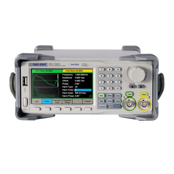
The Front Panel at a Glance 3. Screen Display 4. Numeric Keyboard 5. Knob 2.USB Host 6. Arrow Keys 8. Channel Select Key 1.Power Switch 11. Menu Keys 9. Function Keys 7. CH1/CH2 Control/Output Port 10. Waveform Option Area SDG1000X_ServiceManual_SM0201X-E01B.docx... - Page 10 The User Interface at a Glance SDG1000X can only display parameters and waveform for one channel at a time. The picture below shows the interface when CH1 is selected and AM modulation of a sine wave function is selected. The information displayed may vary depending on the function selected.
- Page 11 output key for two second to switch between High Impedance and 50 Ω. High Impedance: display HiZ. Load: display impedance value (the default is 50 Ω and the range is 50 Ω to 100 kΩ). Note: This setting does not actually change the instrument’s output impedance of 50 Ω...
-
Page 12: The Rear Panel At A Glance
The Rear Panel at a Glance 10 MHz Clock Input/Output Aux In/Out Aux In/Out Counter Earth Terminal AC Power Supply Input LAN Interface USB Device WARNING: For protection from electric shock, the grounding power cord must not be defeated. If only a two-contact electrical outlet is available, connect the instrument’s chassis ground screw (see above) to a good earth ground. -
Page 13: Chapter 1 Quick Start
Chapter 1 Quick Start One of the first things you will want to do with your generator is to become acquainted with the front panel. We have written the exercises in this chapter to prepare the instrument for use and help you get familiar with some of its front- panel operations. -
Page 14: To Prepare The Generator For Use
To Prepare the Generator for Use 1. Check the list of accessories Accessories supplied with the instrument are listed below. If anything is missing or damaged, please contact your nearest SIGLENT Sales Office. ⚫ Quick Start Guide ⚫ Certification of compliance ⚫... -
Page 15: To Adjust The Carrying Handle
To Adjust the Carrying Handle To adjust the position, grasp the handle by the sides and pull outward. Then, rotate the handle to the desired position. Pull the handle ahead for easy carrying Pull the handle down SDG1000X_ServiceManual_SM0201X-E01B.docx... -
Page 16: To Set The Output Frequency
To Set the Output Frequency The following steps explain change the frequency to 20 KHz. 1. Press the Parameter softkey Press the Parameter softkey to enter the parameter set interface. The waveform parameters including Frequency/Period, Amplitude/HighLevel, Offset/LowLevel and Phase are ready to modify using the numeric keypad. 2. - Page 17 Then press the corresponding softkey to select the desired unit. For example, press kHz. Note: The desired numerical value can be modified using the knob and direction keys. SDG1000X_ServiceManual_SM0201X-E01B.docx...
-
Page 18: To Set The Output Amplitude
To Set the Output Amplitude The following steps describe how to change the amplitude to 8 Vpp. 1. Press the Amplitude/HighLevel softkey The displayed amplitude is either the power-on value or the amplitude previously selected. When changing the function, the same amplitude is used if the current value is valid for the new waveform. -
Page 19: To Set The Dc Offset
To Set the DC offset The following steps describe how to change offset to 1 Vdc. 1. Press the Offset/LowLevel softkey The displayed offset is either the power-on value or the offset previously selected. When changing the function, the same offset is used if the current value is valid for the new waveform. - Page 20 Note: The desired numerical value can be modified using the knob and direction keys. SDG1000X_ServiceManual_SM0201X-E01B. docx...
-
Page 21: To Set The Duty Cycle Of A Square Waveform
To Set the Duty Cycle of a Square Waveform At power-on, the default duty cycle for square wave is 50%. The duty cycle setting range is limited by the “Frequency/Period” setting. The following steps show how to change the duty cycle to 80%. 1. - Page 22 SDG1000X_ServiceManual_SM0201X-E01B. docx...
-
Page 23: To Set The Symmetry Of A Ramp Waveform
To Set the Symmetry of a Ramp Waveform At power-on, the Symmetry for Ramp wave is 50%. The symmetry can be adjusted between 0% and 100%. The following steps describe the procedure to set the symmetry to 60%. 1. Select the Ramp wave function Press Waveforms →... - Page 24 SDG1000X_ServiceManual_SM0201X-E01B. docx...
-
Page 25: To Generate A Pulse Waveform
To Generate a Pulse Waveform The generator can be set to output a pulse waveform with variable width, edge time and delay time. The following steps show you how to generate a 500 µs period pulse waveform with a pulse width of 100 µs, rise time of 8 ns and delay time of 50 ns. - Page 26 4. Set the Edge Time Press the Rise/Fall softkey and then set the rising edge to 10 ns. 5. Set the Pulse Delay Press the Delay softkey and then set the delay time to 50 ns. SDG1000X_ServiceManual_SM0201X-E01B. docx...
- Page 27 SDG1000X_ServiceManual_SM0201X-E01B.docx...
-
Page 28: To Generate A Noise Waveform
To Generate a Noise Waveform The generator can be set to output a noise waveform with an adjustable Stdev and Mean. The following steps show you how to generate a noise waveform with 500 mV Stdev and 1 mV Mean. 1. - Page 29 3. Set the Mean Press the Mean softkey and then set the mean to 1 mV. SDG1000X_ServiceManual_SM0201X-E01B.docx...
-
Page 30: To Set The Dc Voltage
To Set the DC Voltage The following steps show how to set a dc voltage with +1 Vdc. 1. Select the DC function Press Waveforms → Page 1/2 → DC to select the DC function. 2. Set the DC Offset Use the digital keypad to input the value directly, enter the value “1”. - Page 31 SDG1000X_ServiceManual_SM0201X-E01B.docx...
-
Page 32: To Output A Built-In Arbitrary Waveform
To Output a Built-In Arbitrary Waveform There are approximately 200 built-in arbitrary waveforms stored in non-volatile memory. The following steps show how to output the built-in “exponential fall” waveform from the front panel. 1. Set the arbitrary waveform function Press Waveforms → Page 1/2 → Arb Type → Built-In to enter the arbitrary waveform setting interface. - Page 33 Rotate the knob to select the ExpFall waveform and press the knob. The waveform is output with the present settings unless they are changed. SDG1000X_ServiceManual_SM0201X-E01B.docx...
-
Page 34: To Use The Built-In Help System
To Use the Built-In Help System The built-in help system is designed to provide context-sensitive assistance of some functions. A list of help topics is also available to assist you with several operations. 1. Read the help information Press Utility → System → Page 1/2 → Help to enter the following interface. You will see a list of help topics as below. -
Page 35: Chapter 2 Performance Verification
Chapter 2 Performance Verification Performance Verification Test The performance verification tests are recommended as acceptance tests upon receipt of the instrument. The acceptance test results should be compared against the specifications given in the data sheet. After acceptance, repeat the performance verification tests at every calibration interval. -
Page 36: Dc Output Verification
DC Output Verification This test checks if the DC offset listed in the table below are within the specified range using a DMM. 1. Set the DMM to measure DC voltage. Connect the DMM to the CH1 output of the generator as shown below. 2. -
Page 37: Ac Amplitude Verification
AC Amplitude Verification This test checks the AC amplitude output accuracy at the frequency of 10 kHz using a DMM. 1. Turn on the generator and choose CH1 as the operating channel. Set the Load to HiZ. 2. Connect the DMM and generator as shown below. 3. -
Page 38: Frequency Response Verification
Frequency Response Verification This test checks if the amplitude flatness is within the spec range using a PC controlled Power Meter. If you do not have a PC controlled Power Meter, simply ignore the USB connections shown. 1. Turn on the generator and choose CH1 as the operating channel. Set the Load to 50 Ω. -
Page 39: Chapter 3 Assembly Procedures
Chapter 3 Assembly Procedures This chapter describes how to remove the major modules from the SDG1000X series generator. To install the removed modules or replace new modules, please follow corresponding operating steps in reverse order. The following subjects are addressed in this chapter: ⚫... -
Page 40: List Of Modules
materials from the immediate work area. ◆ Use only anti-static solder suckers. List of Modules The following removable modules are listed in the order of performing disassembly procedures. Number of Module Module Handle Metal Shell and Rear Cabinet Front Cabinet Display Module Main Body Required Tools... -
Page 41: Disassembly Procedures
Disassembly Procedures This section describes how to remove and install the generator’s modules listed above in detail. Complete disassembly will be best achieved through the following operating steps. 1. Pull out the handle hard from the two sides of the generator. 2. - Page 42 3. Open the cable clamp as ① ② show and pull out the cable as ③ ④ ⑤ ⑥ show, and then remove the 5 screws as shown in the following figure. 4. Separate the front panel from the main body of the generator. 5.
- Page 43 6. Remove the keypad circuit board assembly. SDG1000X_ServiceManual_SM0201X-E01B.docx...
- Page 44 7. Remove the 3 screws holding the screen bracket and remove the metal front panel. 8. Pull out the connecting cable according to the index number as shown in the following figure and remove the keyboard. 9. Remove all the 9 screws fixed the main board and power supply board using the T10 Torx screwdriver and separate the main board and power supply board carefully from the main body of the generator to avoid being scratched by the sharp metal edge.
- Page 45 10. Pull out the connecting cable as shown in the following figure and then remove the fan, rear interface board, channel board and main board. Note: To assemble the generator, please follow these same steps in reverse order. SDG1000X_ServiceManual_SM0201X-E01B.docx...
-
Page 46: Chapter 4 Troubleshooting
(mainly main board and channel board) by measuring the corresponding test points and checking the signals of connectors on them, thus to help in determining the reason for the failure that has been encountered while operating the SDG1000X series arbitrary waveform generator. ESD Precautions... -
Page 47: Channel Board Drawing
Channel Board Drawing The channel board is a kind of signal conditioning board for generating analog signal. It mainly deals with the adjusting of signal parameters such as frequency, amplitude, and so on. Please refer to the following drawing to quickly locate the test points on the channel board for easy resolution of any problems encountered. -
Page 48: Main Board Drawing
Main Board Drawing The main board is the control center of the generator that contains an ARM CPU system. It completes the GUI function, controlling and configuration function of the channel board as well as the user interface. Please refer to the following drawing to quickly locate the test points on the main board for easy resolution of any problems encountered. -
Page 49: Check The Power Supply
Check the Power Supply There are two power connectors through which the channel board and main board can be supplied power. Before performing the power supply testing procedure, please make sure that the generator is grounded correctly through the protective lead of the power cord. - Page 50 6.5 V VL+(yellow) ± 30% -6.5 V VL-(blue) ± 30% If each tested voltage value is within the specified range listed in the table above, then some abnormality of the load is most likely causing the power supply problem. Continuous checking or even replacing the channel/main board is required for further test.
-
Page 51: Check The Channel Board
Check the Channel Board If it is desired to remove the channel board from the metal shelf inside the generator, please place it on a clean, insulated mat. Here are the procedures for testing the main board: 1. Several types of connectors are used on the channel board. Check to make certain that all of these are connected properly. -
Page 52: 25 Mhz Clock Source Checking
25 MHz Clock Source Checking There is an oscillator chip generating a 25 MHz 3.3 V LVCOMS clock source to the entire channel board. Please check it, referring to the marked point on the channel board drawing. FPGA Checking To check if the FPGA is working properly, please observe the test point marked with FPGA_LED on the channel board drawing. -
Page 53: Check The Main Board
Check the Main Board If the power board does need to be removed from the metal shelf located inside the generator, place it on a clean, insulated mat. Testing procedures for the main board are as follows: 1. Several types of connectors are located on the main board. Check if all these are connected properly. -
Page 54: Arm Cpu System Verification
ARM CPU System Verification Observe the ARM_LED light on the main board, which indicates the working state of ARM CPU system. If the light turns on, then the corresponding codes have been loaded successfully and the chip is in an operating state. Otherwise, there may be a problem with it. -
Page 55: Quick Guide For General Failures
Quick Guide for General Failures The general hardware failures are described in the following. Reading the following information can help in determining the cause of some general hardware failures: 1. No start-up after pressing the power button: (1) Check if the power cord is correctly connected. (2) Check if the power button is operating correctly. -
Page 56: Chapter 5 Maintenance
Chapter 5 Maintenance Maintenance Summary SIGLENT warrants that the products it manufactures and sells are free from defects in materials and workmanship for a period of three years from the date of shipment from an authorized SIGLENT distributor. If a product proves defective within the respective period, SIGLENT will provide repair or replacement as described in the complete warranty statement. -
Page 57: Contact Siglent
Contact SIGLENT Headquarters SIGLENT TECHNOLOGIES CO., LTD. Blog No.4 & No.5, Antongda Industrial Zone, 3rd Liuxian Road, Bao’an District, Shenzhen, 518101, China. Tel:+ 86 755 3688 7876 Fax:+ 86 755 3359 1582 sales@siglent.com www.int.siglent.com/ North America SIGLENT Technologies America, Inc...
Need help?
Do you have a question about the SDG1000X Series and is the answer not in the manual?
Questions and answers