
Subscribe to Our Youtube Channel
Related Manuals for SIGLENT TECHNOLOGIES SDG1000 Series


Summary of Contents for SIGLENT TECHNOLOGIES SDG1000 Series
- Page 1 Service Manual SDG1000 Series Function/Arbitrary Waveform Generator SM02010-E01B 2014 SIGLENT TECHNOLOGIES CO., LTD...
-
Page 3: Guaranty And Declaration
Copyright SIGLENT TECHNOLOGIES CO., LTD. All Rights Reserved. Trademark Information SIGLENT is the registered trademark of SIGLENT TECHNOLOGIES CO., LTD Declaration SIGLENT products are protected by patent law in and outside of P.R.C. SIGLENT reserves the right to modify or change parts of or all the specifications or pricing policies at company’s sole decision. -
Page 4: General Safety Summary
General Safety Summary Carefully read the following safety precautions to avoid person injury and prevent damage to the instrument or any products connected to it. To avoid potential hazards, please use the instrument as specified. Only qualified technician should perform service procedures Use Proper Power Line Use only the special power line of the instrument that approved by local state. -
Page 5: Safety Terms And Symbols
Safety Terms and Symbols Terms used on the instrument. Terms may appear on the instrument: DANGER: Indicates an injury or hazard that may immediately happen. WARNING: Indicates an injury or hazard that may not immediately happen. CAUTION: Indicates a potential damage to the instrument or other property that might occur. -
Page 6: Overview For The Document
Overview for the Document The document is for SDG1000 series arbitrary waveform generator, which will be mostly written as generator for short in the following text. The main contents described in this manual are: SDG1000 Series Generator at a glance This part introduces the main technology characteristics for SDG1000 generator. - Page 7 Convention for the whole Contents All the description for function and performance in this document are according to SDG1050 series generator, and apply to generator of the other types. The SDS1000 series contains the following types: Type Analog Bandwith Channel SDG1005 5 MHz SDG1010...
-
Page 8: Sdg1000 Series At A Glance
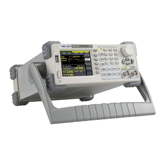
SDG1000 Series at a Glance The SDG1000 series is a direct digital synthesized waveform generator with built-in arbitrary waveform and pulse capabilities. Its combination of excellent system features, easiness in usage and versatile functions makes this generator a perfect solution for your testing now and in the future. -
Page 9: The Front Panel At A Glance
The Front Panel at a Glance Description Description ON/OFF Switch Direction Keys USB Host Output Control Keys LOGO BNC Connectors Model Function Keys Menu ON/OFF Switch Waveform Selection Keys Digital Keypad Menu Operation Keys Universal Knob LCD Display SDG1000 Service Manual... - Page 10 The Front Panel Display at a Glance Output Status Softkey Parameter Name Parameter Unit Value Channel Display Space Mod Information Trigger Information VIII SDG1000 Service Manual...
-
Page 11: The Rear Panel At A Glance
The Rear Panel at a Glance 1. External 10 MHz Reference Input Terminal 2. Sync Output Terminal 3. Chassis Ground 4. Power Socket 5. USB Device 6. Ext Trig/Gate/FSK/Burst Terminal 7. External Modulation Input Terminal WARNING: For protection from electric shock, the power cord ground must not be defeated. -
Page 12: Table Of Contents
Guaranty and Declaration .................I General Safety Summary.................II Safety Terms and Symbols ................III Overview for the Document................IV SDG1000 Series at a Glance................. VI The Front Panel at a Glance ................. VII The Rear Panel at a Glance................IX Specification.....................1 Specifications.....................1 General Specifications................7... - Page 13 Channel Self Adjustment ..............31 Square Adjustment ................32 Frequency Response Adjustments ............33 Assembly Procedures ..................34 Security Consideration ..............34 List of Modules ..................35 Required Tools...................35 Disassembly Procedures..............35 A view of the whole Instrument ..............36 Removing the Handle ................37 Removing the Metal Shell and Rear Cabinet...........38 Removing the Front Cabinet..............40 Removing the Display Module ..............41 Removing the Main Body.................43...
-
Page 15: Specification
Specification These specifications apply to SDG1000 series Arbitrary Waveform Generator. To verify that an oscilloscope meets specifications, it must first meet the following conditions: The generator must have been operating continuously for fifteen minutes within the specified operating temperature. - Page 16 Frequency Specification SDG1005 SDG1010 SDG1020 SDG1025 SDG1050 Waveform Sine, Square, Ramp, Pulse, Noise, Arb Sine 1μHz ~5MHz 1μHz ~10MHz 1μHz ~ 20MHz 1μHz ~25MHz 1μHz ~50MHz Square 1μHz ~ 5MHz 1μHz ~ 10MHz 1μHz ~ 20MHz 1μHz ~ 25MHz 1μHz ~ 25MHz Pulse 500μHz~5MHz 500μHz ~ 10MHz...
- Page 17 Pulse Wave Pulse width Max. 1998 s; Min. 16 ns; resolution 1 ns Rise/Fall time (10% ~ 90%, typical value, 7 ns 1 kHz,1Vpp) Duty Cycle (0.1% ~ 99.9%) 0.1% Resolution Overshoot < 5% Jitter 8 ns Ramp Wave < 0.1% of Peak value output Linearity (typical value, 1 kHz, 1Vpp, symmetric 100%)...
- Page 18 ± 5 V (50Ω) ±1.5 V (50Ω) Range(DC) ±10 V (high resistance) ± 3 V (high resistance) Offset accuracy ±(|setting offset value|1%+3 mV) ±(|setting offset value|1%+3 mV) Waveform Output Impedance 50Ω(typical value short - circuit protection Protection AM Modulation(CH1/CH2) Carrier Sine, Square,Ramp,Arbitrary(except DC)...
- Page 19 Sweep(CH1/CH2) Carrier Sine, Square, Ramp, Arbitrary (except DC) Type linear/logarithmic Direction Up / down Sweep time 1 ms ~ 500 s Trigger source Manual, external, internal Burst(CH1/CH2) Waveform Sine, Square, Ramp, Pulse, Arbitrary(except DC) Count(1 ~ 50,000 cycles) ,infinite,Gated Type Start/Stop phrase 0°...
- Page 20 Frequency Counter Measurement Frequency, Period, Positive/negative pulse width, duty cycle Frequency range Single Channel: 100 mHz ~ 200 MHz Frequency resolution 6 bit Voltage range and sensitivity(non-modulated signal) DC offset range ±1.5 VDC DC coupling 100 mHz ~ 100 MHz 50mVrms ~ ±2.5 V Manual 100 MHz ~ 200 MHz...
-
Page 21: General Specifications
General Specifications Display Display type 3.5’TFT-LCD Resolution 320×RGB×240 Color depth 24 bit Contrast(typical value) 350:1 Backlight intensity 300cd/m (typical ) Power 100 ~ 240 VAC , 45 ~ 66 Hz, CATII Voltage 100 ~ 127 VAC , 45 ~ 440 Hz, CATII <... -
Page 22: Quick Start
Quick Start One of the first things you will want to do with your generator is to become acquainted with the front panel. We have written the exercises in this chapter to prepare the instrument for use and help you get familiar with some of its front-panel operations. -
Page 23: Prepare The Generator For Use
Prepare the Generator for Use 1. Check the list of accessories Accessories supplied with the instrument are listed below. If anything is missing or damaged, please contact your nearest SIGLENT Sales Office. • A Quick Start • A Certification • A Guaranty Card •... -
Page 24: Adjust The Carrying Handle
Adjust the carrying Handle To adjust the position, grasp the handle by the sides and pull outward. Then, rotate the handle to the desired position. Pull the handle ahead for easy carrying Pull the handle down SDG1000 Service Manual... -
Page 25: Set The Output Frequency
Set the Output Frequency The following steps show you how to change the frequency to 1.5 MHz. 1. Press the Freq/Period softkey The displayed frequency is either the power-on value or the frequency previously selected. When you change the function, the same frequency is used if the current value is valid for the new waveform. -
Page 26: Set The Output Amplitude
Set the Output Amplitude The following steps show you how to change the amplitude to 100mVrms. 1. Press the Ampl/HLevel softkey The displayed amplitude is either the power-on value or the amplitude previously selected. When you change the function, the same amplitude is used if the current value is valid for the new waveform. -
Page 27: Set The Dc Offset
Set the DC offset The following steps show you how to change offset to -2mVdc. 1. Press the Offset/LLevel softkey The displayed offset is either the power-on value or the offset previously selected. When you change the function, the same offset is used if the current value is valid for the new waveform. -
Page 28: Set The Duty Cycle Of A Square Wave
Set the Duty Cycle of a Square Wave At power-on, the duty cycle for square wave is 50%. You can adjust the duty cycle from 20% to 80% for output frequencies up to 10 MHz. The following steps show you how to change the duty cycle to 30%. 1. -
Page 29: Set The Symmetry Of A Ramp Wave
Set the Symmetry of a Ramp Wave At power-on, the Symmetry for Ramp wave is 50%. You can adjust the symmetry from 0% to 100%. The following steps show you how to change the symmetry to 60%. 1. Select the Ramp wave function Press Ramp button and then select the desired output frequency to any value. -
Page 30: Generate A Pulse Waveform
Generate a Pulse Waveform You can set the generator to output a pulse waveform with variable width and delay time. The following steps show you how to generate a 500 µs pulse waveform with a pulse width of 100 µs and delay time of 50 ns. 1. -
Page 31: Configure A Noise Waveform
Configure a Noise Waveform You can set the generator to output a noise waveform with variance and mean. The following steps show you how to generate a noise waveform with 2V variance and 1mV mean. 1. Select the Noise function Press the Noise button to select the noise function and output a noise waveform with the default parameters. -
Page 32: Set The Dc Voltage
Set the DC Voltage You can set the DC Voltage feature from the Utility Menu, and then set a dc voltage as an “Offset” value. The following steps show you how to set a dc voltage with +1Vdc. 1. Select the Utility function Press the Utility button to select the Utility function. -
Page 33: Output A Built-In Arbitrary Waveform
Output a Built-In Arbitrary Waveform There are 48 built-in arbitrary waveforms stored in non-volatile memory. The following steps show you how to output the built-in “exponential fall” waveform from the front panel. 1. Select the arbitrary waveform function Press the button to select the arbitrary waveform function. -
Page 34: Use The Built-In Help System
Use the Built-In Help System The built-in help system is designed to provide context-sensitive assistance of some functions. A list of help topics is also available to assist you with several operations. 1. View the help information for SDG1000 Press Help button, you will see the list of help topics. Use the konb and directional keys to select the help title. -
Page 35: Calibration
Calibration This calibration procedure contains performance verification procedure and adjustment procedure. After receiving a generator, you should firstly verify if its performance applies to the limits, and then perform adjustment in case of abnormal testing results. Calibration Interval The instrument should be calibrated on a regular interval determined by the measurement accuracy requirements of your application. -
Page 36: Recommended Test Equipment
Recommended Test Equipment The test equipment recommended for the performance verification and adjustment procedures is listed below. If the exact instrument is not available, substitute calibration standards of equivalent accuracy. Instrument Requirements Recommended Model dc volts Digital Multimeter(DMM) accuracy: 100ppm Agilent 34401A resolution: 100μV Frequency:... -
Page 37: Performance Verification Test
Performance Verification Test Use the performance verification tests to verify the measurement performance of the instrument. The performance verification tests use the instrument’s specifications listed in the “Specifications” chapter. You can perform two different levels of performance verification tests: Self Adjust A series of internal verification tests that give high confidence that the instrument is operational. -
Page 38: Performance Verification Tests
Performance Verification Tests The performance verification tests are recommended as acceptance tests when you first receive the instrument. The acceptance test results should be compared against the specifications given in chapter 1. After acceptance, you should repeat the performance verification tests at every calibration interval. If the instrument fails performance verification, adjustment or repair is required. -
Page 39: Dc Output Verification
DC Output Verification This test checks if the DC offset listed in the table below are within the spec range using a DMM. 1. Set the DMM to measure DC voltage. Connect the DMM to the channel 1 output of the generator as shown below. 2. -
Page 40: Duty Cycle Verification For Square
Duty Cycle Verification for Square This test checks if the Square Duty Cycle listed in the table below is within the spec range using a digital oscilloscope. 1. Turn on the generator and choose CH1 as the operating channel. Select Square waveform and set the frequency to 100 kHz, amplitude to 4Vpp, duty to 20%. -
Page 41: Frequency Response Verification
Frequency Response Verification This test checks if the value in dB format translated from output amplitude is within the spec range response to different frequency using a Power Meter. 1. Turn on the generator and choose CH1 as the operating channel. Set the load to 50Ω... -
Page 42: Ac Amplitude Verification
AC Amplitude Verification This test checks the ac amplitude output accuracy at the frequency of 100 kHz using a Power Meter. 1. Turn on the generator and choose CH1 as the operating channel. Set the load to 50Ω in OUTPUT SETUP system under the Utility menu. 2. -
Page 43: General Adjustment Procedure
General Adjustment Procedure This chapter explains how to adjust the SDG1000 series generator for optimum operating performance. The following contents are the four adjustment steps: Feedback channel Adjustment which act as a standard calibration module, providing the accuracy assurance for Self Adjust. -
Page 44: Feedback Channel Adjustment
Feedback Channel Adjustment The internal feedback channel receives the feedback signal from all the other channels that are performing self adjustment. This adjustment acts as a standard test module and must be performed prior to Self Adjust to make sure it is performed based on a best adjusting accuracy. -
Page 45: Channel Self Adjustment
Channel Self Adjustment This adjustment is for internal control channel and signal channel. Through feedback circuits of the feedback channel and signal channel, this adjustment helps to obtain the actual working performance for components from signal channels. 1. After the feedback channel adjustment completed, disconnect the two BNC cables on channel 1 and channel 2. -
Page 46: Square Adjustment
Square Adjustment This procedure adjusts the square duty to limit its error in the range of ±1%. 1. Connect the Digital oscilloscope, PC and SDG1000 generator as shown below: 2. Open the EasyTest software on the desktop, and run the square adjustment script prepared previously. -
Page 47: Frequency Response Adjustments
Frequency Response Adjustments This adjustment aims to obtain the actual frequency response characteristic of signal channel, thus to perform appropriate compensation. Since the waveform amplitude will decrease as the input frequency increases, it is essential to compensate for the amplitude to match it to the frequency. 1. -
Page 48: Assembly Procedures
Assembly Procedures This chapter describes how to remove the major modules from the SDG1000 series Generator. To install the removed modules or replace new modules, please follow corresponding operating steps in reverse order. The following contents are what mainly included in this chapter: ... -
Page 49: List Of Modules
Minimize handling. Keep replacement parts in original static-free packaging. Remove all plastic, foam, vinyl, paper and other static-generating materials from the immediate work area. Use only anti-static solder suckers. List of Modules The following removable modules are listed in the order of performing disassembly procedures. -
Page 50: A View Of The Whole Instrument
A view of the whole Instrument The disassembly drawing are shown as below for you to disassemble the generator in right steps. Before disassembling, please cut the power to avoid any personal injuries or damages to inside components. Since some modules of the instrument are sharp, you should also take care while operating to prevent being scratched. -
Page 51: Removing The Handle
Removing the Handle Table 4-2 Removing the handle Removing steps: Pull down the handle hard from the two sides of the generator. To install the handle, please operate as the reverse steps. SDG1000 Service Manual... -
Page 52: Removing The Metal Shell And Rear Cabinet
Removing the Metal Shell and Rear Cabinet Table 4-3 Removing the rear cabinet screws Table 4-4 Removing the metal shell screw SDG1000 Service Manual... - Page 53 Removing steps: 1. Remove the two screws from the rear cabinet of the generator using a PH2 philips screw driver. 2. Remove the screw from the bottom of the generator using the screw driver. 3. Remove the rear cabinet and metal shell from the main body. To install the metal shell and rear cabinet, please operate as the reverse steps.
-
Page 54: Removing The Front Cabinet
Removing the Front Cabinet Table 4-6 Removing the front cabinet Removing steps: 1. Remove the front module cable connected to the main board. 2. Remove the screws from the front cabinet using a PH2 philips screw driver. 3. Separate the front cabinet from the main body of the generator. To install the front cabinet, please operate as the reverse steps. -
Page 55: Removing The Display Module
Removing the Display Module Table 4-8 Removing the display module screws Removing steps: 1. Remove the screws from the keypad circuit board using a PH2 philips screw driver. 2. Remove the keypad circuit board, soft keypad and LCD screen from the front cabinet in sequence. - Page 56 Table 4-9 Removing the front cabinet module SDG1000 Service Manual...
-
Page 57: Removing The Main Body
Removing the Main Body Table 4-10 Removing the main body Removing steps: 1. Remove the screws from the rear metal cover using the screw driver. 2. Remove the rear metal cover from the main body of the generator. 3. Remove the screws from the main board and power supply board and using the screw driver. - Page 58 Table 4-11 Assembly drawing of the main body SDG1000 Service Manual...
-
Page 59: Troubleshooting
Troubleshooting The internal structure of the generator consists of main board, power supply board and keypad circuit board, and they are linked through cables or connectors. This chapter explains the main checking procedures for main board and power supply by measuring the pointed test points on them to help you decide the reason for the failure you encounter while operating SDG1000 series arbitrary waveform generator. -
Page 60: Main Board Drawing
Main Board Drawing Please refer to the following drawing to quickly locate the test points on the main board for easy resolution of the failures you encounter. SDG1000 Service Manual... - Page 61 SDG1000 Service Manual...
-
Page 62: Check The Power Supply
Check the Power Supply Before performing the power supply testing procedure, please make sure that the generator is grounded correctly through the protective lead of the power cord. Take care not to touch or even disassemble the power supply module without any safety precautions, or you may probably suffer from electric shock or burn. -
Page 63: Check The Main Board
Check the Main Board If you want to remove the main board from the metal shelf inside the generator, you’d better place it on a clean, insulated mat. In addition, to avoid some chips or components on the main board being damaged for overheating, it is essential to cool the main board whenever possible using a fan. - Page 64 Table 5-4 Signal test points for the main board Test point Voltage/Frequency Error limit ±10% TA15 1.5V (Sine wave) ±10% TA16 1.5V (Sine wave) ±50ppm T4(clock signal) 25MHz TA15 is tested for CH1 output waveform. In the case of abnormal display of channel 1 on the oscilloscope screen, if the tested voltage is within the spec range, then the failure results from analog channel.
-
Page 65: Quick Guide For General Failures
Quick Guide for General Failures The general hardware failures are described as below. Reading the following information can help you quickly handle some easy hardware failures with more convenience. 1. No start-up after pressing the Power button: (1) Check if the power cord is correctly connected. (2) Check if the power button is usable. -
Page 66: Maintenance
Maintenance Maintain Summary SIGLENT warrants that the products it manufactures and sells are free from defects in materials and workmanship for a period of three years from the date of shipment from an authorized SIGLENT distributor. If a product or CRT proves defective within the respective period, SIGLENT will provide repair or replacement as described in the complete warranty statement. -
Page 67: Repackaging For Shipment
Repackaging for Shipment If the unit needs to be shipped to SIGLENT for service or repair, be sure to: 1. Attach a tag to the unit identifying the owner and indicating the required service or repair. 2. Place the unit in its original container with appropriate packaging material for shipping. -
Page 68: Contact Siglent
Contact SIGLENT SIGLENT TECHNOLOGIES CO., LTD Address:3/F, building NO.4, Antongda Industrial Zone, 3rd Liuxian Road, Bao’an District, Shenzhen, P.R.China Tel:0086-755-3661 5186 E-mail:sales@siglent.com http://www.siglent.com SDG1000 Service Manual...
Need help?
Do you have a question about the SDG1000 Series and is the answer not in the manual?
Questions and answers