Table of Contents
Advertisement
Quick Links
Advertisement
Table of Contents

Related Manuals for SIGLENT TECHNOLOGIES SDG7000A Series


Summary of Contents for SIGLENT TECHNOLOGIES SDG7000A Series
- Page 1 SDG7000A Series Arbitrary Waveform Generator Service Manual EN01A...
- Page 2 Copyright SIGLENT TECHNOLOGIES CO., LTD. All Rights Reserved. Trademark Information SIGLENT is the registered trademark of SIGLENT TECHNOLOGIES CO., LTD. Declaration SIGLENT products are protected by patent law in and outside of P.R.C. SIGLENT reserves the right to modify or change parts of or all the specifications or pricing policies at company’s sole decision.
-
Page 3: Table Of Contents
IMPORTANT SAFETY INFORMATION ....................6 ......................6 ENERAL AFETY UMMARY ......................8 AFETY ERMS AND YMBOLS THE SDG7000A SERIES GENERATOR AT A GLANCE..............9 ........................... 9 HARACTERISTICS ..................... 10 RONT ANEL AT A LANCE 3.2.1 Touch Screen Display ......................... 11 ....................... - Page 4 SDG7000A Service Manual ......................36 HECK THE HANNEL OARD 6.9.1 Voltage Checking ..........................36 6.9.2 Connector Checking ..........................37 6.10 Q ....................38 UICK UIDE FOR ENERAL AILURES MAINTENANCE ..........................39 ........................39 AINTAIN UMMARY ......................39 EPACKAGING FOR HIPMENT www.siglent.com...
-
Page 5: Introduction
Introduction Overview of this Document This document is for the SDG7000A series arbitrary waveform generator, which will be mostly referred to as “the generator” for short in the following text. The main contents described in this manual are: The SDG7000A Series Generator at a Glance This section introduces the main technology characteristics for the SDG7000A generator. - Page 6 The Different SDG7000A Models Addressed by this Manual All the description for function and performance in this document are according to the SDG7102A generator, and apply to all generators in this series. The SDG7000A series contains the following types: The series includes the following models:...
-
Page 7: Important Safety Information
SDG7000A Service Manual Important Safety Information This manual contains information and warnings that must be followed by the user for safe operation and to keep the product in a safe condition. General Safety Summary Carefully read the following safety precautions to avoid personal injury and prevent damage to the instrument and any products connected to it. - Page 8 SDG7000A Service Manual to the company's designated maintenance organization for maintenance. Be sure to pull out the power cord before repairing the device. Live line operation is strictly prohibited. The device can only be powered on when the maintenance is completed and the maintenance is confirmed to be successful. Identification of Normal State of Equipment.
-
Page 9: Safety Terms And Symbols
SDG7000A Service Manual Safety Terms and Symbols When the following symbols or terms appear on the front or rear panel of the instrument or in this manual, they indicate special care in terms of safety. This symbol is used where caution is required. Refer to the accompanying information or documents to protect against personal injury or damage to the instrument. -
Page 10: The Sdg7000A Series Generator At A Glance
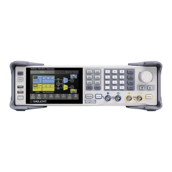
SDG7000A Service Manual The SDG7000A Series Generator at a Glance SIGLENT’s SDG7000A is a series of dual-channel Arbitrary Waveform Generators that feature up to 1 GHz maximum bandwidth, maximum sample rate of 5 GSa/s and 14-bit vertical resolution. They also include proprietary TrueArb and EasyPulse technology that helps to solve the weaknesses inherent in traditional DDS generators when generating arbitrary, square and pulse waveforms. -
Page 11: The Front Panel At A Glance
SDG7000A Service Manual The Front Panel at a Glance www.siglent.com... -
Page 12: Touch Screen Display
SDG7000A Service Manual 3.2.1 Touch Screen Display Home Page Carrier Setting Boxes set and display parameters of the carrier. Click to enter the carrier setting page. Modulation/Sweep/Burst Setting Boxes display parameters modulation/sweep/burst. Click to enter the modulation/sweep/burst setting page. Waveform Combine Setting provides schematic diagram and setting of two channel combine. - Page 13 SDG7000A Service Manual Parameter Setting Page Channel Tab Click the tab corresponding to the channel to switch to the parameter setting page of the channel. Waveform Preview Displays the preview of waveform. Parameter Setting Box The parameter name is on the left. If the parameter name is ,it indicates that the parameter has alternative parameters, such followed by an icon as "Frequency"...
-
Page 14: The Rear Panel At A Glance
SDG7000A Service Manual Description of Icons in the Status Bar The network is connected. Click this icon to quickly set the LAN. No network connection. Click this icon to quickly set the LAN. USB storage device detected. The clock source is internal. Click this icon to quickly set the clock source. The clock source is external. -
Page 15: Performance Verification
SDG7000A Service Manual Performance Verification The performance verification tests are recommended as acceptance tests upon receipt of the instrument. The acceptance test results should be compared to the specifications given in datasheet. After acceptance, repeat the performance verification tests within every calibration interval. If the instrument fails performance verification, adjustment or repair is required. - Page 16 SDG7000A Service Manual DC Offset Spec Range ± (1%+2 mV) 0 mV -2 mV ~ 2 mV 10 mV 7.9 mV ~ 12.1 mV 100 mV 97 mV ~ 103 mV 0.988 V ~ 1.012 V 2.968 V ~ 3.032 V 10 V 9.898 V ~ 10.102 V -10 mV...
-
Page 17: Ac Amplitude Verification
SDG7000A Service Manual AC Amplitude Verification This test checks the ac amplitude output accuracy at the frequency of 10 kHz using a DMM. Turn on the generator and choose CH1 as the operating channel. Connect the DMM and generator as shown below. Set CH1 format to single-ended and set the Load to HiZ. - Page 18 SDG7000A Service Manual Amplitude Spec Range (Vpp) (Vpp) (Vpp) ± (1% +2 mVpp) 8.908~9.902 3.958~4.042 0.988~1.012 0.394~0.406 0.13 0.1267~0.1333 0.04 0.0376~0.0424 Set CH1 format to differential set the Load to HiZ. Set offset to 0V and set the amplitude to the values listed below in sequence. Spec Range Amplitude (Vpp)
-
Page 19: Frequency Response Verification
SDG7000A Service Manual Frequency Response Verification This test checks if the amplitude flatness is within the spec range using a Power Meter. Turn on the generator and choose CH1 as the operating channel. Set the Load to 50 Ω. Connect the Power Meter, PC and generator as shown below. Set CH1 format to single-ended. - Page 20 SDG7000A Service Manual ± 0.3 ± 0.3 450 MHz CH1_1M CH2_1M ± 0.3 ± 0.3 500 MHz CH1_1M CH2_1M ± 0.3 ± 0.3 550 MHz CH1_1M CH2_1M ± 0.3 ± 0.3 600 MHz CH1_1M CH2_1M ± 0.3 ± 0.3 650 MHz CH1_1M CH2_1M ±...
- Page 21 SDG7000A Service Manual ± 0.3 ± 0.3 300 MHz CH1_1M_dif CH2_1M_dif ± 0.3 ± 0.3 350 MHz CH1_1M_dif CH2_1M_dif ± 0.3 ± 0.3 400 MHz CH1_1M_dif CH2_1M_dif ± 0.3 ± 0.3 450 MHz CH1_1M_dif CH2_1M_dif ± 0.3 ± 0.3 500 MHz CH1_1M_dif CH2_1M_dif ±...
-
Page 22: Frequency Accuracy Verification
SDG7000A Service Manual Frequency Accuracy Verification This test checks if the frequency accuracy is within the spec range using a frequency counter. Set the Frequency Counter to measure frequency. Connect the Counter to the CH1 output of the generator as shown below. Power up the frequency counter and the generator for 30 minutes. -
Page 23: Assembly Procedures
SDG7000A Service Manual Assembly Procedures This chapter describes how to remove the major modules from the SDG7000A series generator. To install the removed modules or replace new modules, please follow corresponding operating steps in reverse order. The following subjects are addressed in this chapter: ... -
Page 24: List Of Modules
SDG7000A Service Manual List of Modules The following removable modules are listed in the order of performing disassembly procedures. Number of Module Module Metal Shell Channel Board Main Board Front Cabinet Required Tools Use these tools to remove or replace the modules in the generator: ... -
Page 25: Disassembly Procedures
SDG7000A Service Manual Disassembly Procedures This section describes in detail how to disassemble the generator’s modules listed above. If you need to install or replace the part module, follow the reverse steps. 5.4.1 Disassemble the Metal Shell Figure 5-1 Disassemble the Metal Shell Disassemble according to the following steps: Remove 4 PCS PM4 * 8 screws from the rear foot pad and remove the rear foot pad. -
Page 26: Disassemble The Channel Board
SDG7000A Service Manual 5.4.2 Disassemble the Channel Board Figure 5-2 Disassemble the Channel Board Disassemble according to the following steps: Pull out the cable plug from ① to ⑪ as shown in the figure above. Remove 6 PCS screws fixing the channel board. Remove the channel board. -
Page 27: Disassemble The Main Board
SDG7000A Service Manual 5.4.3 Disassemble the Main Board Figure 5-3 Disassemble the Main Board Disassemble according to the following steps: Pull out the cable plug from ⑫ to ⑳ as shown in the figure above. Remove 18 PCS PM3 * 6 screws and take out the cooling air duct, support frame and PCBA in turn. -
Page 28: Disassemble The Front Cabinet
SDG7000A Service Manual 5.4.4 Disassemble the Front Cabinet Figure 5-4 Disassemble the Front Cabinet Disassemble according to the following steps: Remove the 8 PCS PM4 * 8 screws of the front foot pad and take out the front foot pad. Remove 4 PCS PM4 * 8 screws from the front cabinet and separate the front cabinet assembly from the frame. -
Page 29: Troubleshooting
SDG7000A Service Manual Troubleshooting The internal structure of the generator consists of the CPU card, main board, channel board, key and LCD board, USB interface board, power module, OCXO module, and fans. They are linked through cables or connectors. This chapter explains the main troubleshooting procedures for these boards (mainly main board, channel board, and CPU card) by measuring the corresponding test points and checking the signals of connectors on them, thus to help in determining the cause of the failure that has been encountered while operating the SDG7000A. -
Page 30: Cpu Card Drawing
SDG7000A Service Manual CPU Card Drawing The CPU card is the control center of the generator that contains an ARM CPU system. It completes the GUI function, controlling and configuration function of the main board and the channel board as well as the user interface. -
Page 31: Main Board Drawing
SDG7000A Service Manual Main Board Drawing The main board is responsible for signal processing. It is mainly responsible for generating analog signal, clock, input and output interface signal and other functions. Please refer to the following drawing to quickly locate the test points on the main board for easy resolution of any problems encountered. -
Page 32: Channel Board Drawing
SDG7000A Service Manual Channel Board Drawing The channel board is a signal conditioning board. It mainly deals with the adjusting of signal parameters such as amplitude, offset, and so on. Please refer to the following drawing to quickly locate the test points on the channel board for easy resolution of any problems encountered. www.siglent.com... -
Page 33: Check The Power Supply
SDG7000A Service Manual Check the Power Supply Before performing the power supply testing procedure, please make sure that the generator is grounded correctly through the protective lead of the power cord. Take care not to touch or even disassemble the power supply module without any safety precautions to avoid electric shock. Here are procedures for testing the power supply: Disconnect the power cord of the generator and then check whether the fuse is good. -
Page 34: Check The Cpu Card
SDG7000A Service Manual Check the CPU Card The CPU card is the control center of the generator where an Arm CPU is located. Please refer to chapter 8 if you wish to separate it from the main board. 6.7.1 Voltage Checking Test the voltage test points on the CPU card and compare to the table below. -
Page 35: Check The Main Board
SDG7000A Service Manual Check the Main Board If it is desired to remove the main board from the metal shelf inside the generator, please place it on a clean, insulated mat. Here are the procedures for testing the main board: Several types of connectors are used on the main board. -
Page 36: 10 Mhz Clock Source And Pll Lock Status Checking
SDG7000A Service Manual 6.8.2 10 MHz Clock Source and PLL Lock Status Checking There is a TXCO/OCXO generating a 10 MHz clock source to the PLL. The PLL lock to the clock source and generate all clock for the entire main board. Please check whether the PLL LED is on. If it is on, it is locked. -
Page 37: Check The Channel Board
SDG7000A Service Manual Check the Channel Board If it is desired to remove the channel board from the metal shelf inside the generator, please place it on a clean, insulated mat. Here are the procedures for testing the channel board: Several types of connectors are used on the channel board. -
Page 38: Connector Checking
SDG7000A Service Manual 6.9.2 Connector Checking Table 6-6 Connectors of the Channel Board Connector Function J9, J38 Communication between the main board and the channel board. Power supply of the channel board. J1, J2, J3, J4 Analog input from the main board. J5, J6, J7, J8 Analog output to BNC connector of the front panel. -
Page 39: 6.10 Quick Guide For General Failures
SDG7000A Service Manual 6.10 Quick Guide for General Failures The general hardware failures are described in the following. This information may help in determining the cause of some general hardware failures: No start-up after pressing the power button: Check if the power cord is correctly connected. Check if the power switch under the AC inlet is turn on. -
Page 40: Maintenance
SDG7000A Service Manual Maintenance Maintain Summary SIGLENT warrants that the products it manufactures and sells are free from defects in materials and workmanship for a period of three years from the date of shipment from an authorized SIGLENT distributor. If a product proves defective within the respective period, SIGLENT will provide repair or replacement as described in the complete warranty statement. - Page 41 We firmly believe that today SIGLENT is the best value in electronic test & measurement. Headquarters: SIGLENT Technologies Co., Ltd Add: Bldg No.4 & No.5, Antongda Industrial Zone, 3rd Liuxian Road, Bao'an District, Shenzhen, 518101, China...
Need help?
Do you have a question about the SDG7000A Series and is the answer not in the manual?
Questions and answers