
Related Manuals for SIGLENT TECHNOLOGIES SDG6000X Series


Summary of Contents for SIGLENT TECHNOLOGIES SDG6000X Series
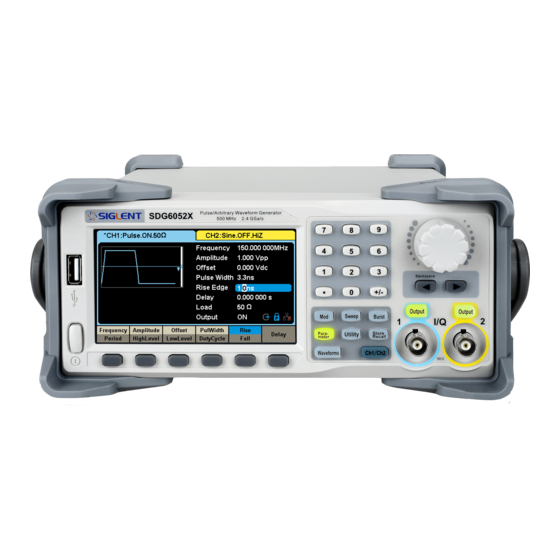
- Page 1 User Manual SDG6000X Series Pulse/Arbitrary Waveform Generator UM0206X-E01A 2017 SIGLENT TECHNOLOGIES CO., LTD...
- Page 3 Declaration Copyright © SIGLENT TECHNOLOGIES CO., LTD. All rights reserved. Without permission, contents in this manual are not allowed to be copied, extracted or translated. SDG6000X User Manual...
-
Page 4: General Safety Summary
General Safety Summary Carefully read the following safety precautions to avoid any personal injury or damage to the instrument and any product connected to it. To avoid potential hazards, please use the instrument as specified. Only qualified technical personnel should service this instrument. Avoid fire or open flame. - Page 5 Safety Terms and Symbols Terms used in this manual: DANGER: Indicates an injury or hazard that may immediately happen. WARNING: Indicates an injury or hazard that may not immediately happen. CAUTION: Indicates that a potential damage to the instrument or other property might occur.
-
Page 6: Introduction
Introduction The manual covers the following 3 models of SDG6000X Series Pulse/Arbitrary Waveform Generators: SDG6022X, SDG6032X SDG6052X. SIGLENT‟s SDG6000X is a series of dual-channel Pulse/Arbitrary Waveform Generators that feature up to 500 MHz maximum bandwidth, a maximum sample rate of 2.4 GSa/s and 16-bit vertical resolution. They also include proprietary TrueArb &... - Page 7 Key Features Dual-Channel, 500 MHz maximum bandwidth, 20 Vpp maximum output amplitude, high fidelity output with 80dB dynamic range High-performance sampling system with 2.4 GSa/s maximum sampling rate and 16-bit vertical resolution. Multi-function signal generator that delivers: Up to 500 MHz sine wave, supporting sweep and Continuous Wave user-defined harmonics.
-
Page 8: Table Of Contents
Content Declaration ....................... I General Safety Summary ................II Introduction ....................IV Quick Start ....................1 Handle Adjustment ............... 2 The Front/Rear Panel ..............3 1.2.1 Front Panel ................3 1.2.2 Rear Panel ................4 Touch Screen Display ..............5 System Functions ................. - Page 9 2.4.3 FM ..................76 2.4.4 PM ..................78 2.4.5 FSK ..................80 2.4.6 ASK ..................82 2.4.7 PSK ..................83 2.4.8 PWM ..................85 To Set Sweep Function ............... 87 To Set the Burst Function ............92 To Store and Recall ..............97 2.7.1 Storage System ..............
- Page 10 3.10 Example 10: Generating an FM Modulation Waveform .... 166 3.11 Example 11: Generating a PM Modulation Waveform ....168 3.12 Example 12: Generating a FSK Modulation Waveform .... 170 3.13 Example 13: Generating an ASK Modulation Waveform ..172 3.14 Example 14: Generating a PSK Modulation Waveform ....
-
Page 11: Quick Start
1 Quick Start This chapter covers the following topics: Handle Adjustment The Front/Rear Panel Touch Screen Display System Functions SDG6000X User Manual... -
Page 12: Handle Adjustment
1.1 Handle Adjustment To adjust the handle position of SDG6000X, please grip the handle by the sides and pull it outward. Then, rotate to the desired position. Figure 1-1 Viewing Position and Carrying Position SDG6000X User Manual... -
Page 13: The Front/Rear Panel
1.2 The Front/Rear Panel This chapter will provide a brief introduction and description for the operation and functions of the front/rear panel. 1.2.1 Front Panel SDG6000X has a clear and simple front panel which includes 4.3 inch touch screen, menu softkeys, numeric keyboard, knob, function keys, arrow keys, and channel control area, etc. -
Page 14: Rear Panel
1.2.2 Rear Panel The rear panel provides multiple interfaces, including Counter, 10 MHz In, 10 MHz Out, Aux In/Out, LAN, USB Device, Earth Terminal and AC Power Supply Input. 10 MHz Clock Input Counter Earth Terminal In/Out 10 MHz Clock AC Power Supply Output Input... -
Page 15: Touch Screen Display
1.3 Touch Screen Display SDG6000X displays parameter and waveform information of one channel at a time. The picture below shows the interface when CH1 is selected. In this example, the waveform is an AM modulated sine wave. The information displayed may vary depending on the function selected. The entire screen of the SDG6000X is a touch screen. - Page 16 shortcut menu of front panel's function keys will be shown: Mod, Sweep, Burst, Parameter, Utility and Store/Recall. 3. Basic Waveform Parameters Area Shows the current waveform parameters of each channel. Click the parameters to be set, and the parameters will be selected and highlighted. Then use number keys or knob to change the parameter value.
- Page 17 This mark indicates LAN connection is successful. This mark indicates there is no LAN connection or LAN connection is unsuccessful. 6. Mode Icon The display will show different prompt messages based on the current phase mode. This mark indicates current phase mode is Phase-locked. This mark indicates current phase mode is Independent.
-
Page 18: System Functions
1.4 System Functions In this section, you will learn the main function settings of the SDG6000X, including waveform selection settings, modulation/sweep/burst settings, channel output control, numeric input control and common function keys. 1.4.1 Waveform Selection Press Waveforms to enter the menu as Figure 1-5 shows. The example below will help to familiarize with the waveform selection settings. - Page 19 generator can generate square waveforms with frequencies from 1 μHz to 120 MHz and a variable duty cycle. By setting Frequency/Period, Amplitude/High level, Offset/Low level, Phase and Duty Cycle, a square waveform with different parameters can be generated. Figure 1-7 Square Display Interface Press Waveforms →Ramp, and channel status bar displays "Ramp".
- Page 20 Figure 1-8 Ramp Display Interface Press Waveforms →Pulse, and channel status bar displays "Pulse". The generator can generate pulse waveforms with frequencies from 1 μHz to 150 MHz with variable pulse width and rise/fall times. By setting Frequency/Period, Amplitude/High level, Offset/Low level, PulWidth/Duty, Rise/Fall and Delay, a pulse waveform with different parameters can be generated.
- Page 21 Figure 1-10 Noise Display Interface Press Waveforms →Page 1/2→DC, and channel status bar displays "DC". The generator can generate a DC signal with a level up to ± 10 V into a HighZ load or ± 5 V into a 50 Ω load. Figure 1-11 DC Display Interface Press Waveforms →Page 1/2→Arb, and channel status bar displays "Arb".
- Page 22 Frequency/Period, Amplitude/High level, Offset/Low level, Phase and Interpolation, an arbitrary signal with different parameters can be generated. Figure 1-12 Arbitrary Waveform Display Interface Press Waveforms →Page 1/2→I/Q, then CH1 and CH2 output orthogonal I and Q signals respectively and channel status bar displays " In-phase" and " Quadrature"...
- Page 23 Press Waveforms →Page 1/2→PRBS, and channel status bar displays "PRBS". The generator can generate a Pseudo-Random Bit Sequence (PRBS) with bit rates ranging from 1 μbps to 300 Mbps. By setting BitRate/Period, Amplitude/High level, Offset/Low level, Length, Logic Level and Rise/Fall, A PRBS with different parameters can be generated.
-
Page 24: To Set The Modulation/Sweep/Burst
1.4.2 To Set the Modulation/Sweep/Burst As shown in Figure 1-15, there are three keys on the front panel which select modulation, sweep and burst settings. The instructions below will help to explain these functions. Figure 1-15 Modulate/Sweep/Burst Key 1. Press Mod, the Modulation function will be enabled. The modulated waveform can be changed by modifying the parameters such as Type, Source, AM Depth, AM Freq, and Shape. - Page 25 Figure 1-17 Sweep Waveform Display Interface 3. Press Burst, the Burst function will be enabled. Burst function is supported for Sine, Square, Ramp, Pulse or Arbitrary waveforms. Start Phase ranges from 0° to 360° and the Burst Period ranges from 1 μs to 1000 s. Figure 1-18 Burst Waveform Display Interface SDG6000X User Manual...
-
Page 26: Output Control
1.4.3 Output Control As shown in Figure 1-19, there are two keys on the right side of the front panel which are used to enable / disable the output of the two channels. Choose a channel and press the corresponding Output key, the key backlight will light and the output will be enabled. -
Page 27: Numeric Input
1.4.4 Numeric Input As shown in Figure 1-20, there are three sets of keys on the front panel, which are arrow keys, knob and numeric keyboard. The instructions below will help to familiarize you with the numerical keypad. Figure 1-20 Front Panel Digital Input 1. - Page 28 Figure 1-21 Use numeric keyboard to set the parameters When using the numeric keyboard to enter the value, the left arrow key can be used to move the cursor backward and delete the value of the previous digit. SDG6000X User Manual...
-
Page 29: Common Function Keys
1.4.5 Common Function Keys As shown in Figure 1-22, there are five keys on the operation panel, which are labeled Parameter, Utility, Store/Recall, Waveforms, and Ch1/Ch2. The instructions below will help to familiarize you with these functions. Figure 1-22 Common Function Keys 1. -
Page 30: Application And Implementation
2 Application and Implementation Up to now, you have got a brief understanding about SDG6000X with the front/rear panel, the function control areas, and keys. You should also know how to set your Pulse/Arbitrary Waveform Generator for your usage. If you are not familiar with these operations, you are suggested to read chapter one „Quick Start‟... -
Page 31: To Set The Standard Waveforms
2.1 To Set the Standard Waveforms The SDG6000X can output 8 standard waveforms; including sine, square, ramp, pulse, noise, DC, arbitrary and PRBS. In this section, you will learn how to set the parameters of each waveform. 2.1.1 To Set the Sine Waveform Press Waveforms key to select the waveform function and then press the Sine softkey. - Page 32 example, if you wish to adjust the period of a waveform, press the softkey below the “Frequency/Period” menu label until Period is highlighted and then enter the value. To Set the Frequency/Period Frequency is one of the most important parameters of basic waveforms. For different instrument models and waveforms, the available ranges of frequency are different.
- Page 33 Press Waveforms → Sine → Amplitude, to set the amplitude parameter. If the new value is invalid, the instrument will set the value to the closest valid setpoint. For example, if you set the amplitude to “0 V”, which is not a valid amplitude, the instrument will select the nearest valid value.
- Page 34 amplitude, the instrument will select the nearest valid value. If the low value is the parameter you wish to set, press Offset/LowLevel again to switch to low level entry. Figure 2-4 Setting the Offset To Set the Phase Press Waveforms → Sine → Phase, to set the phase parameter. When changing parameter, if the new value is valid, the value will be set.
-
Page 35: To Set The Square Waveform
2.1.2 To Set the Square Waveform Press Waveforms key to select the waveform function, and press the Square softkey. The square waveform parameters are set by using the Square operation menu, as shown in Figure 2-6. The parameters of square waveforms include frequency/period, amplitude/high level, offset/low level, phase and duty cycle. - Page 36 To Set the Duty Cycle Duty Cycle: The ratio of the positive pulse width to the period. The duty cycle setting range is limited by the “Frequency/Period” setting. For detailed information, please refer to “SDG6000X Datasheet”. The default value is 50%. Press Waveforms →...
-
Page 37: To Set The Ramp Waveform
2.1.3 To Set the Ramp Waveform Press Waveforms key to select the waveform function, and press the Ramp softkey. The ramp waveform parameters are set by using the ramp operation menu, as shown in Figure 2-8. The parameters for ramp waveforms include frequency/period, amplitude/high level, offset/low level, phase and symmetry. - Page 38 To Set the Symmetry Symmetry: The percentage that the rising period relative to the waveform period. Range: 0~100% Default Value: 50% Press Waveforms → Ramp → Symmetry, to set the symmetry parameter. When changing parameter, if the new value is valid, the value will be set. Otherwise, the nearest valid value will be set.
-
Page 39: To Set The Pulse Waveform
2.1.4 To Set the Pulse Waveform Press Waveforms key to select the waveform function, and press the Pulse softkey. The pulse waveform parameters are set by using the pulse operation menu, as shown in Figure 2-10. The parameters for pulse waveforms include frequency/period, amplitude/high level, offset/low level, width, rise/fall and delay. - Page 40 below the “Frequency/Period” menu label until Period is highlighted and then enter the value. To Set the Pulse Width/DutyCycle Pulse width is defined as the time from the 50% threshold of a rising edge amplitude to the 50% threshold of the next falling edge amplitude (as shown in the figure below).
- Page 41 Figure 2-11 Setting the Pulse Width To Set the Rise/Fall Edge Rise edge time is defined as the duration of the pulse amplitude rising from 10% to 90% threshold, while fall edge time is defined as duration of the pulse amplitude moving down from 90% to 10% threshold.
- Page 42 Figure 2-12 Setting the Rise Edge Note: The methods of setting other parameters of pulse signal are similar to sine waveform function. Refer to “To Set the Sine Waveform” to configure other parameters. SDG6000X User Manual...
-
Page 43: To Set The Noise Waveform
2.1.5 To Set the Noise Waveform Press Waveforms key to select the waveform function, and press the Noise softkey. The noise parameters are set by using the noise operation menu, as shown in Figure 2-13. The parameters for noise include stdev, mean and bandwidth. - Page 44 Figure 2-14 Setting the Stdev To Set the Mean Press Waveforms → Noise → Mean, to set the mean parameter. When changing parameter, if the new value is valid, the value will be set. Otherwise, the nearest valid value will be set. Figure 2-15 Setting the Mean Bandwidth Press Waveforms →...
- Page 45 Figure 2-16 Setting the Bandwidth SDG6000X User Manual...
-
Page 46: To Set The Dc Waveform
2.1.6 To Set the DC Waveform Press Waveforms → Page 1/2 → DC, to enter the following interface. Please note that there is a „DC offset‟ parameter at the middle of the screen. Figure 2-17 DC Setting Interface Note: The method of setting offset of a DC signal is similar to Offset of the sine waveform function. -
Page 47: To Set The Arbitrary Waveform
2.1.7 To Set the Arbitrary Waveform The Arb signal consists of two types: the system‟s built-in waveforms and the user-defined waveforms. Built-in waveforms are stored in the internal non-volatile memory. TrueArb output mode allows creation of arbitrary waveforms that contain from 2 to 20 Mpts. TrueArb Choose Waveforms →... - Page 48 Table 2-6 Menu Explanations of Arb Waveform Function Explanations Menu SRate/ Set the signal sampling rate or frequency Frequency Amplitude/ Set the signal amplitude or high level press HighLevel Offset/ Set the signal offset or low level press LowLevel Arb Mode Set the output mode to TrueArb or DDS Arb Type Select either built-in or stored waveforms...
- Page 49 Interpolation in the operation menu. Figure 2-19 shows the output waveform comparison of a 32-point sinusoidal arbitrary wave with "0-order hold" interpolation and "linear" interpolation. Figure 2-19 Comparison of "0-order hold" and "Linear" Interpolation Modes Choose Waveforms → Page 1/2 → Arb → Arb Mode and select the “DDS” output mode.
- Page 50 In DDS output mode, users can set the frequency or period of the arbitrary waveform. The instrument outputs an arbitrary waveform which is made up of certain points according to the current frequency. Note: The methods of setting other parameters of arbitrary signal are similar to sine waveform function.
- Page 51 rotate the knob or click the touch screen to choose the desired waveform (the selected waveform will be highlighted). Select Accept or press the knob to recall the corresponding waveform. Table 2-7 Built-in Waveforms Item Waveform Explanation StairUp Stair-up waveform StairDn Stair-down waveform StairUD...
- Page 52 Item Waveform Explanation Gaussian Gaussian function Dlorentz Dlorentz function Haversine Haversine function Lorentz Lorentz function Gauspuls Gauspuls signal Gmonopuls Gmonopuls signal Tripuls Tripuls signal Weibull Weibull distribution LogNormal LogNormal Gaussian distribution Laplace Laplace distribution Maxwell Maxwell distribution Rayleigh Rayleigh distribution Cauchy Cauchy distribution Cardiac...
- Page 53 Item Waveform Explanation Gamma Gamma signal StepResp Step-response signal BandLimited Bandwidth-limited signal CPulse C-Pulse CWPulse CW pulse GateVibr Gate self-oscillation signal LFMPulse Linear FM pulse MCNoise Mechanical construction noise Hamming Hamming window Hanning Hanning window Kaiser Kaiser window Blackman Blackman window GaussiWin Gaussian window Triangle...
- Page 54 Item Waveform Explanation Csch Hyperbolic cosecant SecH Hyperbolic secant SinH Hyperbolic sine SinInt Integral sine TanH Hyperbolic tangent ACosH Arc hyperbolic cosine ASecH Arc hyperbolic secant ASinH Arc hyperbolic sine ATanH Arc hyperbolic tangent ACsch Arc hyperbolic cosecant ACoth Arc hyperbolic cotangent SquareDuty01 Square waveform with 1% duty cycle SquareDuty02...
- Page 55 Item Waveform Explanation SquareDuty46 Square waveform with 46% duty cycle SquareDuty48 Square waveform with 48% duty cycle SquareDuty50 Square waveform with 50% duty cycle SquareDuty52 Square waveform with 52% duty cycle SquareDuty54 Square waveform with 54% duty cycle SquareDuty56 Square waveform with 56% duty cycle SquareDuty58 Square waveform with 58% duty cycle SquareDuty60...
- Page 56 Item Waveform Explanation ECG2 Electrocardiogram 2 ECG3 Electrocardiogram 3 ECG4 Electrocardiogram 4 ECG5 Electrocardiogram 5 ECG6 Electrocardiogram 6 ECG7 Electrocardiogram 7 ECG8 Electrocardiogram 8 ECG9 Electrocardiogram 9 ECG10 Electrocardiogram 10 ECG11 Electrocardiogram 11 ECG12 Electrocardiogram 12 ECG13 Electrocardiogram 13 ECG14 Electrocardiogram 14 ECG15 Electrocardiogram 15...
- Page 57 Figure 2-22 Stored Waveform Display Interface Rotate the knob or touch the screen to choose the desired waveform. Then select Recall or press the knob to recall the corresponding waveform. SDG6000X User Manual...
-
Page 58: To Set The Pseudo Random Binary Sequence (Prbs)
2.1.8 To Set the Pseudo Random Binary Sequence (PRBS) Press Waveforms key to select the waveform function, and then press the PRBS softkey. The parameters of pseudo random binary sequence (PRBS) are set by using the PRBS operation menu, as shown in Figure 2-23. The parameters of PRBS include bitrate/period, amplitude/high level, offset/low level, length, logic level and rise/fall. - Page 59 below the “Frequency/Period” menu label until Period is highlighted and then enter the value. To Set the BitRate/Period Press Waveforms → Page 1/2 → PRBS → BitRate, to set the bit rate parameter. When changing parameter, if the new value is valid, the value will be set.
- Page 60 Figure 2-25 Setting the Length To Set the Logic Level Press Waveforms → Page 1/2 → PRBS → Logic Level, to set the logic level. By selecting the corresponding type of logic level, the high level and low level of PRBS can be configured automatically. If Differential is set to ON, channel one will output the waveform with normal polarity while channel two will output the waveform with inverted polarity.
- Page 61 Table 2-9 Correspondence between logic level and high, low level Logic Level High Level Low Level TTL/CMOS LVTTL/LVCOMS 3.3 V -900 mV -1.7 V LVPECL 2.4 V 1.6 V LVDS 1.6 V 900 mV To Set the Rise/Fall Edge Press Waveforms → Page 1/2 → PRBS → Rise/Fall, to set the rise/fall edge parameter.
-
Page 62: Harmonic Function
2.2 Harmonic Function The SDG6000X can be used as a harmonic generator to output harmonics with specified order, amplitude and phase values. According to the Fourier transform, a periodic time domain waveform is the superposition of a series of sine waveforms as shown in the equation below: Generally, the component with the frequency term f is called the fundamental φ... - Page 63 Table 2-10 Menu Explanations of Harmonic Function Explanations menu Set the harmonic type to “odd”, “ever” or “all” Type Order Set the order of the harmonic Harmonic Set the amplitude of the harmonic Ampl Harmonic Set the phase of the harmonic Phase Cancel Return to the sine parameters menu...
- Page 64 keyboard to input the amplitude value and then select the desired unit from the pop-up menu. The units available are Vpp, mVpp and dBc. To Set the Harmonic Phase After entering the harmonic setting menu, press Harmonic Phase to set the phase of selected harmonic.
-
Page 65: To Set Iq Waveform (Optional)
2.3 To Set IQ Waveform (Optional) The SDG6000X can be used as an IQ waveform generator, providing ASK, PSK, QAM, FSK, MSK and multi-tone signals. The EasyIQ software is necessary when using SDG6000X to generate an IQ waveform. The EasyIQ is a PC program used to download IQ baseband waveform data to the SDG6000X through a USB or LAN device interface. - Page 66 To Set the Center Frequency Press Parameter→ Center Frequency, to set the center frequency. The range of center frequency is 0Hz ~ 500MHz. If the center frequency is 0Hz, the two channels will output the IQ baseband signal. If the center frequency is not zero the two channels will output an intermediate frequency (IF) IQ modulation signal whose center frequency is the intermediate frequency.
- Page 67 Figure 2-32 Setting the Symbol Rate To Set the Amplitude Press Parameter→ Amplitude to set the amplitude. When the unit is V , mV or dBm, the amplitude equal-to the modulus of the I / Q ( Figure 2-33 Setting the Amplitude To Set the Trigger Source Press Parameter→Trigger Source, to set the Trigger Source, including internal trigger, external trigger and manual trigger, as shown in Figure 2-34.
- Page 68 Figure 2-34 Setting the Trigger Source 1. Internal Trigger Choose Trigger Source → Internal. Internal trigger is the default trigger source of IQ playback. 2. External Trigger Choose Trigger Source → External, and the generator accepts the trigger signal inputted from the [Aux In/Out] connector at the rear panel. One period of the IQ waveform will be generated for every trigger signal received at the Aux In/Out input 5V CMOS pulse with the specified polarity.
- Page 69 waveform. Rotate the knob to select the .arb file and then push down the knob or press the Recall key to recall the IQ data. The Browse key is used to enter the subdirectory, and the Delete key is used to delete the selected file. Note: When the EasyIQ downloads a waveform from PC to the instrument, the instrument will store the waveform as a .arb file.
-
Page 70: Easyiq Software
2.3.2 EasyIQ Software The IQ baseband waveform data can be generated by the EasyIQ software. The setting of EasyIQ includes Data Source, Modulation and Filter, as show in Figure 2-36. Figure 2-36 EasyIQ Interface 2.3.2.1 Data Source Data Source panel sets parameters for the symbol data that is to be modulated. - Page 71 Data Setup Selects a data source type for modulation. Choices: PN7 | PN9 | PN15 | PN23 | User File | Customer Bit Pattern Default: PN9 PN7 | PN9 | PN15 | PN23: When selecting “PN7 | PN9 | PN15 | PN23” as data source type, software generates data source bit automatically.
- Page 72 Default: 512 Symbol Rate Sets the symbol rate (symbols per second) of the waveform. Range: 250 to 37500000/Oversampling Symbol/s Default: 1000000 Symbol/s Bits-Per-Symbol Displays the number of bits contained in one modulated symbol. It is read only, not settable. 2.3.2.2 Modulation Modulation panel sets parameters for user selected modulation type.
- Page 73 D8PSK | 8QAM | 16QAM | 32QAM | 64QAM | 128QAM | 256QAM Default: 16QAM After a modulation type is selected, the constellation of current modulation is displayed on right side of the panel: You can double-click on the constellation display to show a zoomed window of the constellation, you can also double click on the zoomed constellation window to close it.
- Page 74 Sets frequency deviation for FSK modulation in Hz. Range: 0 to 0.8 * Symbol Rate * Oversampling Hz Default: 600000 Hz The Symbol and FSK deviation table is displayed on the right side of the panel: MSK: When selecting MSK as current modulation type, the filter type can only be selected as Gaussian.
- Page 75 Figure 2-40 Multi-tone Custom Sets a custom constellation for modulation. After selecting Custom modulation type, a custom constellation editing window is displayed, as shown in Figure 2-41: Figure 2-41 Custom modulation In the custom constellation editing window, you can preset the constellation data to a known modulation type first by pressing buttons, and then you can insert or delete constellation points and edit the IQ data for...
- Page 76 Note: When editing the constellation points, the number of points must be a value of power of 2 and the Symbol values cannot be duplicated, otherwise there will be error message when you click “OK” button. 2.3.2.3 Filter EasyIQ provides three types of filters, including raised cosine filter, root raised cosine filter and Gaussian filter.
- Page 77 BT Range: 0.1~5 Default: 0.5 Filter Length: Set length of filter in symbols. Range: 1~min (Symbol Length, 512) Default: 32 Oversampling: Sets the oversampling factor of the waveform. The waveform Sample Rate is determined based on Symbol Rate and Oversampling factor. Range: 2 - 32.
- Page 78 Figure 2-43 Waveform Spectrum The horizontal coordinate shows the Frequency values in Hz and the vertical coordinate shows the Magnitude values in dB. IQ Waveform Display After clicking “IQ Waveform” tab, the Time domain plot of modulated IQ data is displayed.
- Page 79 generated from current settings or from file which has been exported from the EasyIQ with the ".arb" suffix. Figure 2-45 Download Interface Two types of connection are possible for the EasyIQ to access the SDG6000X: USB Device If the SDG6000X is connected to the PC through USB device correctly, in the "VISA Address"...
- Page 80 address of the SDG6000X to replace the "LOCALHOST" characters, as shown in Figure 2-47. And then click the "download" button to download the waveform data. Figure 2-47 Download Data through LAN SDG6000X User Manual...
-
Page 81: Modulation Functions
2.4 Modulation Functions Press the Mod key to enable modulation. The SDG6000X can generate AM, FM, ASK, FSK, PSK, PM, PWM and DSB-AM modulated waveforms. Modulation parameters vary with the types of the modulation. In AM, users can set the source (internal/external), depth, modulating frequency, modulating waveform and carrier. - Page 82 2.4.1 AM The modulated waveform consists of two parts: the carrier and the modulating waveform. In AM, the amplitude of the carrier varies with the instantaneous voltage of the modulating waveform. Press Mod → Type → AM, the parameters of AM modulation are shown in Figure 2-48.
- Page 83 To Select Modulation Source The SDG6000X can accept a modulating signal from an internal or external modulation source. Press Mod → AM → Source to select “Internal” or “External” modulation source. The default is “Internal”. 1. Internal Source When internal modulation source is selected, press Shape to select Sine, Square, Triangle, UpRamp, DnRamp, Noise or Arb as the modulating waveform.
- Page 84 corresponding parameters, and then set the source to external 3. Select CH2, select the desired modulating waveform and set the corresponding parameters. 4. Press Output to enable the output of CH1 and CH2. To Set Modulation Depth The modulation depth is expressed as a percentage of the overall amplitude set by the amplitude waveform parameter.
-
Page 85: Dsb-Am
2.4.2 DSB-AM DSB-AM is an abbreviation for Double-SideBand Suppressed Carrier – Amplitude Modulation. Press Mod → Type → DSB-AM. The parameters of DSB-AM modulation are shown in Figure 2-49. Figure 2-49 Setting Interface of DSB-AM Modulation Table 2-13 Menu Explanations of the DSB-AM Parameters Function Settings Explanation... - Page 86 2.4.3 FM The modulated waveform consists of two parts: the carrier and the modulating waveform. In FM, the frequency of the carrier varies with the instantaneous voltage of the modulating waveform. Press Mod → Type → FM, the parameters of FM modulation are shown in Figure 2-50.
- Page 87 To Select Modulation Source The SDG6000X can accept a modulating signal from an internal or external modulation source. Press Mod → FM → Source to select “Internal” or “External” modulation source. The default is “Internal”. 1. Internal Source The way of selecting the internal source is similar to AM. 2.
- Page 88 2.4.4 PM The modulated waveform consists of two parts: the carrier and the modulating waveform. In PM, the phase of the carrier varies with the instantaneous voltage level of the modulating waveform. Press Mod → Type → PM, the parameters of PM modulation are shown in Figure 2-51 .
- Page 89 To Select the Modulation Source The SDG6000X can accept a modulating signal from an internal or external modulation source. Press Mod → PM → Source to select “Internal” or “External” modulation source. The default is “Internal”. 1. Internal Source The way of selecting the internal source is similar to AM. 2.
-
Page 90: Fsk
2.4.5 FSK FSK is Frequency Shift Keying, the output frequency of which switches between two preset frequencies (carrier frequency and hop frequency or sometimes known as mark frequency (1) and space frequency (0)). Press Mod → Type → FSK, the parameters of FSK modulation are shown in Figure 2-52. - Page 91 “External” modulation source. The default is “Internal”. 1. Internal Source When internal modulation source is selected, the modulating waveform is a square with 50% duty cycle. 2. External Source When external modulation source is selected, the generator accepts external modulating signal from the [Aux In/Out] connector at the rear panel. The external modulating signal of FSK must be a square wave which complies with 5V CMOS level specification.
-
Page 92: Ask
2.4.6 ASK When using ASK (Amplitude Shift Keying), the amplitude of the modulated waveform switches between the carrier frequency amplitude and zero. The key frequency is the shift rate of modulated waveform amplitude. Press Mod → Type → ASK, the parameters of ASK modulation are shown in Figure 2-53. -
Page 93: Psk
2.4.7 PSK When using PSK (Phase Shift Keying), the generator shifts its output phase by 180° when the modulation source switches. Press Mod → Type → PSK, the parameters of PSK modulation are shown in Figure 2-54. Figure 2-54 Setting Interface of PSK Modulation Table 2-18 Menu Explanations of the PSK Parameters Function Settings... - Page 94 the modulating waveform amplitude corresponds to carrier phase output and logic high corresponds to modulating phase output; if the polarity is “negative”, the situation is the opposite. When external modulation is selected, if the polarity is “positive”, logic low of the input corresponds to carrier phase output and logic high corresponds to modulating phase output;...
-
Page 95: Pwm
2.4.8 PWM In PWM (Pulse Width Modulation), the pulse width of the pulse varies with the instantaneous voltage of the modulating waveform. The carrier can only be pulse. Press Waveforms → Pulse → Mod, the parameters of PWM modulation are shown in Figure 2-55 Figure 2-55 Setting Interface of PWM Modulation Table 2-19 Menu Explanations of the PWM Parameters... - Page 96 To Select Modulation Source The SDG6000X can accept a modulating signal from an internal or external modulation source. Press Source to select “Internal” or “External” modulation source. The default is “Internal”. 1. Internal Source The way of setting internal source is similar to AM. 2.
-
Page 97: To Set Sweep Function
2.5 To Set Sweep Function In sweep mode, the generator changes the output frequency between the start frequency and the stop frequency in the sweep time specified by the user. The waveforms that support sweep include sine, square, ramp and arbitrary. Press Sweep key to enter the following menu. - Page 98 Note: To select the secondary menu item, press the key a second time. For example, if you wish to adjust the period of a waveform, press the softkey below the “Frequency/Period” menu label until Period is highlighted and then enter the value. Figure 2-57 Setting Interface of Sweep (Page 2/2) Table 2-21 Menu Explanations of Sweep (Page 2/2) Function...
- Page 99 frequency for sweep. Start Frequency ≤ Stop Frequency. Choose Direction → Up, the generator will sweep from Start frequency to Stop frequency. Choose Direction → Down, the generator will sweep from Stop frequency to Start frequency. Choose Direction → Up_Down, the generator will sweep from Start frequency to Stop frequency, then from Stop frequency to Start frequency.
- Page 100 Figure 2-58 Linear Sweep Interface Log Sweep In log sweep, the output frequency of the instrument varies in a logarithmic fashion. Choose Sweep → Page 1/2 → Type → Log, there is an exponential function curve displayed on the waveform on the screen, indicating that the output frequency changes in a logarithmic mode.
- Page 101 f = f * 10^[t*lg(f ], t = [0, t start stop start sweep sweep Where f is the Start Frequency, f is the Stop Frequency and t is the start stop sweep Sweep Time. Sweep Trigger Source The sweep trigger source can be internal, external or manual. The instrument will generate a sweep output once a trigger event occurs and then wait for the next trigger.
-
Page 102: To Set The Burst Function
2.6 To Set the Burst Function In Burst mode, the generator could output waveform with specified number of cycles as well as “Gated” bursts using internal or externally gated signals. Sine, Square, Ramp, Pulse or the arbitrary waveform (except Noise or DC) can be used to generate a burst. - Page 103 Figure 2-60 N-Cycle Burst Interface (Page 1/2) Table 2-23 Menu Explanations of the N-Cycle Burst (Page 1/2) Function Settings Explanation Menu NCycle N-Cycle mode Cycles Set the number of the bursts in N-Cycle Infinite Set the number of the bursts in N-Cycle to be infinite Start Phase The start phase of the carrier Burst Period...
- Page 104 Table 2-24 Menu Explanations of the N-Cycle Burst (Page2/2) Function Settings Explanation Menu Trig Delay Set the delay time before the burst starts Disable trigger output Trig Out Enable trigger output Page Return to the previous page Gated In gated mode, the generator controls the waveform output according to the gate signal level.
- Page 105 Negative Start Phase Start phase of the carrier The period of the Gate Burst Period Only valid when Source is Internal Internal Choose internal source as a trigger Source Choose external source as a trigger External Use the [Aux In/Out] connector at the rear panel Start Phase Start point of the burst waveform.
- Page 106 for N cycle and infinite burst mode. When Burst is enabled, press Ncycle → Page 1/2 → Trig Delay and use the numeric keyboard or the knob to input the desired delay. Burst Trigger Source The burst trigger source can be internal, external or manual. The instrument will generate a burst output once a trigger event occurs and then wait for the next trigger.
-
Page 107: To Store And Recall
2.7 To Store and Recall SDG6000X can store the current instrument state and user-defined arbitrary waveform data in internal or external memory and recall them when needed. Press Store/Recall to enter the following interface. Figure 2-63 Store/Recall Interface (Page 1/2) Table 2-26 Menu Explanations of Save and Recall Function Settings... -
Page 108: Storage System
Figure 2-64 Store/Recall Interface (Page 2/2) Table 2-27 Menu Explanations of Save and Recall Function Settings Explanation Menu Copy Copy the selected file Paste Paste the selected file Page Return to the previous page 2.7.1 Storage System The SDG6000X provides an internal non-volatile memory location (C: Disk) and a USB Host interface for external memory. - Page 109 the screen will show the drive letter “USB Device (0:)” and display a prompt message “USB device connected.”. After removing the U-Disk, the screen will display a prompt message “USB device removed.” And “USB Device (0:)” in the storage menu will disappear. Figure 2-65 Storage System Note: The SDG6000X can only identify files whose filenames consist of English...
-
Page 110: File Type
2.7.2 File Type Choose Store/Recall → File Type to select the desired file type. Available file types are State File and Data File. State File Store the instrument state in internal or external memory in “*.xml” format. The state file stored includes waveform parameters and modulation, sweep, burst parameters of two channels and utility parameters. -
Page 111: File Operation
2.7.3 File Operation To Save the Instrument State Users can store the current instrument state in internal and external memories. The storage will save the selected function (including the basic waveform parameters, modulation parameters and other utility settings used.) To save the instrument state, the procedures are given as followed: 1. - Page 112 Table 2-28 Menu Explanation of File Storage Function Explanation Menu Cursor upward to select Down Cursor downward to select Select Select the current character Delete Delete the current character Save Store the file with the current name Cancel Return to the store/Recall interface Select the character Users can select the desired character from the virtual soft keyboard by using the knob or Up and Down menus, then choose Select to input the character...
- Page 113 2. Choose the file to be recalled. Rotate the knob or click the touch screen to select the directory in which the file to be recalled is stored. 3. Recall the file. Press Recall or press the knob or click the location of the file on the screen, the generator will recall the selected file and display corresponding prompt message when the file is read successfully.
- Page 114 Page 1/2 → Copy. 3. Paste the file Rotate the knob to select Local (C:) and press the knob to open its directory. Then press Paste. SDG6000X User Manual...
-
Page 115: To Set Utility Function
2.8 To Set Utility Function With the Utility function, the user can set the Sync, Interface, System Setting, Self Test and Frequency Counter, etc. Press Utility to enter the utility menu, as shown in Figure 2-67, Figure 2-68 and Figure 2-69. Figure 2-67 Utility Setup Interface (Page 1/3) Table 2-29 Menu Explanations of Utility (Page1/3) Function... - Page 116 Figure 2-68 Utility Setup Interface (Page 2/3) Table 2-30 Menu Explanations of Utility (Page 2/3) Function Settings Explanation Menu Interface Remote interfaces setting Sync Sync output setting Clock System clock source setting Phase Phase-Locked Phase mode Mode Independent OverVoltage Turn on/off overvoltage protection...
- Page 117 Table 2-31 Menu Explanations of Utility (Page 3/3) Function Settings Explanation Menu Multi-Device Multi-Device Synchronization setting Sync Page Return to the page 1 SDG6000X User Manual...
-
Page 118: System Settings
2.8.1 System Settings Press Utility → System, to enter the following interface. Figure 2-70 System Setup Interface (Page 1/2) Table 2-32 Menu Explanations of System Setup (Page 1/2) Function Settings Explanation Menu Number The number format format English Language System language Chinese Default All the settings return to default when power on... - Page 119 Figure 2-71 System Setup Interface (Page 2/2) Table 2-33 Menu Explanations of System Setup (Page 2/2) Function Settings Explanation Menu 1min 5min Enable or disable the screen saver and set the 15min ScrnSvr elapsed inactive time that must pass before 30min activating the screen 1hour...
- Page 120 Figure 2-72 Set the Number Format Table 2-34 Menu Explanations of Setting the Number Format Function Settings Explanation Menu Use dot to represent decimal point Point Use comma to represent decimal point Enable the Separator Separator Close the Separator Space Use Space as the separator Save the current settings and return to the Done...
- Page 121 Figure 2-73 English Interface Chinese Interface Figure 2-74 Chinese Interface 2.8.1.3 Power On Choose the SDG6000X‟s setting when the generator is powered on. Three choices are available: "Default", "Last" and "User". Once selected, the setting will be applied when the instrument is powered on. This setting is stored in non-volatile memory and will not be influenced by the Set To Default operation.
- Page 122 channel output state. Default: denotes the factory defaults except certain parameters (such as Language). User: The instrument will automatically recall the setting stored in specified state file when powered on. To specify a state file, press Select File in the interface and recall an instrument state file in “*.xml” format. Figure 2-75 "User"...
- Page 123 AM Depth 100% FM Deviation 100 Hz ASK Key Frequency 100 Hz FSK Key Frequency 100 Hz FSK Hop Frequency 1 MHz PSK Key Frequency 100 Hz PM Phase Deviation 100° 190 μs PWM Width Dev Sweep Default Start/Stop Frequency 500 Hz/1.5 kHz Sweep Time Trig Out...
- Page 124 to resume. 2.8.1.7 System Info Select the System Info option of the utility menu to view the generator‟s system information, including startup times, software version, hardware version, model and serial number. Figure 2-76 System Information Interface 2.8.1.8 Update The software version and configuration file of the generator can be updated directly via U-disk.
- Page 125 Note: 1. Don't cut off the power during the update!If you have any questions, contact your local SIGLENT office. 2. A configuration file (*.CFG) may or may not be included with a given firmware update. If a CFG file is not included with a firmware update then it will not be required for that update.
- Page 126 2.8.1.10 UI Style SDG6000X supports "Normal" and "Classical" style interface. Press Utility → System → Page 1/2 → UI Style, to select the desired interface style. This setting is stored in non-volatile memory and will not be influenced by the Set To Default operation.
-
Page 127: Test/Cal
2.8.2 Test/Cal Choose Utility → Test/Cal, to enter the following interface. Figure 2-80 Test/Cal function Menu Table 2-37 Menu Explanations of Test/Cal Setting Function Explanation Menu SelfTest Perform a system self-test TouchCal Do a touch screen calibration Return Return to the Utility menu Self Test Press Utility →... - Page 128 Table 2-38 Menu Explanations of Self Test Function Explanation Menu ScrTest Run screen test program KeyTest Run keyboard test program LEDTest Run key indicator lights test program BoardTest Run hardware circuit self-test program Cancel Return to the Test/Cal menu 1. ScrTest Select ScrTest to enter the screen test interface.
- Page 129 Figure 2-83 Key Test Interface The corresponding area of tested keys or knob changes to in a blue when a key press is recognized. The top of the screen displays „Please press „8‟ key three times to exit.‟ 3.
- Page 130 4. Board Test Select BoardTest to enter the following interface. Figure 2-85 Board Test Interface Touch Adjust Use the function regularly to calibrate the touch screen, which makes it more accurate when a finger or touch pen touches the screen and avoids any misoperation.
- Page 131 According to the message, click the red circle on the upper left corner, upper right corner, lower left corner and lower right corner of the screen in sequence. After touch calibration is done, the system will display the following tip. Then press any key or touch the screen to exit the current interface.
-
Page 132: Frequency Counter
2.8.3 Frequency Counter The SDG6000X provides a hardware frequency counter which can measure frequencies between 100 mHz to 400 MHz. The dual channels can still output normally when the counter is enabled. Press Utility → Counter, to enter the following interface. Figure 2-88 Frequency Counter Interface Table 2-39 Menu Explanations of Frequency Counter Function... - Page 133 Figure 2-89 Counter Setup Interface Table 2-40 Menu Explanations of Setup Function Settings Explanation Menu Set the coupling mode to DC Mode Set the coupling mode to AC Open the high frequency rejection filter Close the high frequency rejection filter Default Set the frequency counter settings to default Done...
- Page 134 1.5V. Choose TrigLev and use the numeric keyboard to input the desired value and select the unit (V or mV) from the pop-up menu. Or use the knob and arrow keys to change the parameter value. 4. Coupling Mode Sets the coupling model of the input signal to “AC” or “DC”. The default is “AC”.
-
Page 135: Output
2.8.4 Output Press Utility → Output to enter the following interface. Figure 2-90 Output Setup Interface Load For the [CH1] and [CH2] connectors on the front panel, the generator always has an output impedance of 50Ω, but the instrument features a load setting that is used to adjust the displayed amplitude setpoint based on the expected external load impedance. - Page 136 change to display “10 Vpp” when the impedance is changed to “HighZ”. If the load is changed from “HighZ” to “50 Ω”, the displayed amplitude will be reduced half of the previous value. Only the displayed values change with the parameter. The generator output impedance does not change. ...
- Page 137 Press Utility → Output Setup → Wave Combine to enter the waveforms combining interface, as shown in the following figure. Figure 2-91 Waveforms Combining Interface Table 2-41 Menu Explanations of Wave Combine Function Settings Explanation Menu Output the waveform of CH1 CH1 Switch CH1+CH2 Output the waveform of CH1+CH2...
-
Page 138: Copy/Coupling
2.8.5 CH Copy/Coupling Channel Copy The SDG6000X supports state and waveform copy function between its two channels. That is to say, it copies all parameters and states (including the channel output state) and arbitrary waveform data of one channel to the other. Press Utility →... - Page 139 Channel Coupling The SDG6000X supports frequency, amplitude and phase coupling. Users can set the frequency deviation/ratio, amplitude deviation/ratio or phase deviation /ratio of the two channels. When coupling is enabled, CH1 and CH2 can be modified simultaneously. When the frequency, amplitude or phase of one channel (as the reference) is changed, the corresponding parameter of the other channel will be changed automatically and always keeps the specified frequency deviation/ratio, amplitude deviation/ratio or phase deviation /ratio...
- Page 140 signal is represented by: FreqCH2-FreqCH1=FreqDev. Ratio: the frequency ratio of CH1 and CH2. The resulting signal is represented by: Freq /Freq =FreqRatio. Amplitude Coupling 1. To Enable Amplitude Coupling Function Press AmplCoup to turn amplitude coupling “On” or “Off”. The default is “Off”. 2.
- Page 141 3. Channel coupling and channel copy are mutually exclusive. When channel coupling is enabled, the menu Channel Copy is hidden. Channel Track When the track function is enabled, by changing the parameters or states of CH1, the corresponding parameters or states of CH2 will be adjusted to the same values or states automatically.
- Page 142 Figure 2-95 Phase Deviation Interface SDG6000X User Manual...
-
Page 143: Remote Interface
2.8.6 Remote Interface The SDG6000X can be controlled remotely via USB, LAN and GPIB (accomplished through USB-GPIB option) interfaces. Users can set the corresponding interface according to their needs. Press Utility → Page 1/2 → Interface to open the following menu. The user can set LAN parameters or GPIB address. - Page 144 Users can program and control the instrument by using the SCPI commands (Standard Commands for Programmable Instruments). For more information about the commands and programming, please refer to “Remote Control Manual”. 2. PC software Users can use the PC software Measurement & Automation Explorer of NI (National Instruments Corporation) to send commands to control the instrument remotely.
- Page 145 Note: Please make sure that the PC has a GPIB interface card installed. Connect the USB terminal of the USB to GPIB adapter to the USB Host interface at the front panel of the generator and the GPIB terminal to the GPIB card terminal of the PC.
- Page 146 Remote Control via LAN The SDG6000X can communicate with a PC through LAN interface. Users can view and modify the LAN parameters. 1. Connect the device. Connect the generator to your PC or the LAN of your PC using a network cable.
- Page 147 time. 2) To Set Subnet Mask The format of subnet mask is nnn.nnn.nnn.nnn and each nnn ranges from 0 to 255. You are recommended to acquire an available subnet mask from your network administrator. Press Subnet Mask and use the arrow keys and numeric keyboard or knob to enter your desired subnet mask.
- Page 148 “Off” to turn DHCP mode on or off. The default is “Off”. 3. Communicate with PC remotely Open Measurement & Automation Explorer of NI. After adding the LAN device (VISA TCP/IP Resource…) successfully, choose the corresponding device name. Then click “Open VISA Test Panel” to turn on the remote command control panel through which you can send commands and read data.
-
Page 149: Sync Output
2.8.7 Sync Output The generator provides Sync output through the [Aux In/Out] connector on the rear panel. When the synchronization is on, the port will output a CMOS signal with the same frequency as basic waveforms (except Noise and DC), arbitrary waveforms, and modulated waveforms (except external modulation). - Page 150 sync signal is a pulse with 26.7 ns pulse width and the same frequency as the waveform. 2) When the frequency of the waveform is greater than 10 MHz, there is no sync signal output. 3) Noise and DC: There is no sync signal output. 4) PRBS: The frequency of the sync signal is the same as the bit rate of the waveform.
-
Page 151: Clock Source
2.8.8 Clock Source The SDG6000X provides a 10 MHz internal clock source and also accepts external clock source input from the [10MHz In] connector at the rear panel. It can also output a 10 MHz clock source from the [10MHz Out] connector for other device to use. - Page 152 "Enable" is selected, the clock source will be output from [10MHz Out] connector on rear panel. Sync methods for two or more instruments: Synchronization between two instruments Connect the [10 MHz Out] connector of Generator A (“Internal” clock) to the [10MHz In] connector of Generator B (“External”...
-
Page 153: Phase Mode
2.8.9 Phase Mode Press Utility → Page 1/3 → Phase Mode to enter the phase mode setup Interface, as shown in Figure 2-101. Figure 2-101 Mode Setup Interface Phase-locked Mode When changing the frequency, the DDSs of both channels reset, and the phase deviation between CH1 and CH2 is maintained. - Page 154 Independent Mode When changing the frequency, neither channels‟ DDS resets and the phase deviation between CH1 and CH2 changes at random. This mode should be used to minimize the output disruptions when changing frequencies manually. This mode will deliver the smoothes transitions between frequency values. When the independent mode is enabled, the phase parameter cannot be modified and the menu Phase is hidden, as shown in Figure 2-103.
-
Page 155: Overvoltage Protection
2.8.10 Overvoltage Protection Press Utility → Page 1/3 → OverVoltage Protection to turn on or off the function, as shown in the following figure. Figure 2-104 Overvoltage Protection Interface If the state is set to ON, overvoltage protection of CH1 and CH2 will take effect once any of the following conditions is met: ... -
Page 156: Multi-Device Synchronization
2.8.11 Multi-Device Synchronization Press Utility → Page 1/3 → Page 2/3 → Multi-Device Sync to set the function, as shown in Figure 2-105. Figure 2-105 Multi-Device Sync Interface Synchronization of the frequency and alignment of the phase can be realized between two or more SDG6000X instruments by utilizing the Multi-Device Sync function. - Page 157 Note: The synchronous signal is transmitted from [Aux In/Out] of the Master to [Aux In/Out] of the Slave(s) through the BNC cable when Sync Devices is pressed. There is a certain delay between the moment when the master sends the synchronous signal and the moment when the Slave(s) receive it.
-
Page 158: Examples
3 Examples To help the user master how to use the SDG6000X more efficiently, we have provided some examples. All of the examples below use the default setting of the instrument except in special cases. This chapter includes the following topics: ... -
Page 159: Example 1: Generating A Sine Waveform
3.1 Example 1: Generating a Sine Waveform Generate a sine waveform with 1 MHz frequency, 5 Vpp amplitude and 1 Vdc offset by following these steps: Set the frequency. 1. Press Waveforms → Sine →Frequency/Period and choose Frequency which will display in a blue color. 2. - Page 160 Figure 3-1 Generate a Sine Waveform SDG6000X User Manual...
-
Page 161: Example 2: Generating A Square Waveform
3.2 Example 2: Generating a Square Waveform Generate a square waveform with 5 kHz frequency, 2 Vpp amplitude, 1 Vdc offset and 30% duty cycle by following these steps: Set the frequency. 1. Press Waveforms → Square → Frequency/Period and choose Frequency which will display in a blue color. - Page 162 Figure 3-2 Generate a Square Waveform SDG6000X User Manual...
-
Page 163: Example 3: Generating A Ramp Waveform
3.3 Example 3: Generating a Ramp Waveform Generate a ramp waveform with a 10 μs period, 100 mVpp amplitude, 20 mVdc offset, 45° phase and 30% symmetry by following these steps:. Set the Period. 1. Press Waveforms → Ramp → Frequency/Period and choose Period which will display in a blue color. - Page 164 waveform generated is shown in Figure 3-3. Figure 3-3 Generate a Ramp Waveform SDG6000X User Manual...
-
Page 165: Example 4: Generating A Pulse Waveform
3.4 Example 4: Generating a Pulse Waveform Generate a pulse waveform with 5 kHz frequency, 5 V high level, -1 V low level, 40 μs pulse width, 10 ns rising edge, 30 ns falling edge and 20 ns delay by following these steps: ... - Page 166 set to 10 ns. Set the Fall Edge. 1. Press Rise/Fall and choose Fall which will display in a blue color. 2. Input „30‟ from the keyboard and choose the unit „ns‟. The falling edge is set to 30 ns. ...
-
Page 167: Example 5: Generating A Noise
3.5 Example 5: Generating a Noise Generate a noise with 0.5 V stdev and 1 V mean by following these steps: Set the Stdev. 1. Press Waveforms → Noise → Stdev to choose Stdev which will display in a blue color. 2. -
Page 168: Example 6: Generating A Pseudo Random Binary Sequence
3.6 Example 6: Generating a Pseudo Random Binary Sequence Generate a pseudo-random binary sequence with 50 kbps bit rate, 5 V high level, 0 V low level, PRBS-7 length, 20 ns Rise/Fall edge by following these steps: Set the Bit Rate. 1. - Page 169 2. Input „20‟ from the keyboard and choose the unit „ns‟. The bit rate is set to 20 ns. When the bit rate, high level, low level, length and rise/fall edge are set, the waveform generated is shown in Figure 3-6. Figure 3-6 Generate a Pseudo Random Binary Sequence SDG6000X User Manual...
-
Page 170: Example 7: Generating A Linear Sweep Waveform
3.7 Example 7: Generating a Linear Sweep Waveform Generate a sine sweep waveform whose frequency starts at 100 Hz and sweeps to a frequency of 10 KHz. Use internal trigger mode, linear sweep, and a sweep time of 2 s by following these steps: ... - Page 171 When all parameters above are set, the linear sweep waveform generated is shown in Figure 3-7. Figure 3-7 Generate a Linear Sweep Waveform SDG6000X User Manual...
-
Page 172: Example 8: Generating A Burst Waveform
3.8 Example 8: Generating a Burst Waveform Generate a burst waveform with 5 cycles. The burst period is 3 ms. Use internal trigger and 0° start phase. Follow these steps: Set the burst function. Press Waveforms, and choose the sine waveform as the burst function. ... - Page 173 the burst cycle to 5. Set the delay. Press Page 1/2 to choose Delay, and input „100‟ from the keyboard and choose the unit „μs‟ to set the delay to 100 μs. When all parameters above are set, the waveform generated is shown in Figure 3-8.
-
Page 174: Example 9: Generating An Am Modulation Waveform
3.9 Example Generating Modulation Waveform Generate an AM modulation waveform with 80% depth. The carrier is a sine wave with 10 kHz frequency, and the modulating wave is a sine wave with 200 Hz frequency. Follow these steps: Set the frequency, amplitude and offset of the carrier wave. 1. - Page 175 Figure 3-9 Generate an AM Modulation Waveform SDG6000X User Manual...
-
Page 176: Example 10: Generating An Fm Modulation Waveform
3.10 Example 10: Generating an FM Modulation Waveform Generate an FM modulation waveform, the carrier is a sine wave with 10 kHz frequency, and the modulating wave is a sine wave with 1Hz frequency and 2 kHz frequency deviation. Follow these steps: ... - Page 177 Figure 3-10 Generate a FM Modulation Waveform SDG6000X User Manual...
-
Page 178: Example 11: Generating A Pm Modulation Waveform
3.11 Example 11: Generating a PM Modulation Waveform Generate a PM modulation waveform, the carrier is a sine wave with 10 kHz frequency, and the modulating wave is a sine wave with 2 kHz frequency and 90° phase deviation. Follow these steps: ... - Page 179 Figure 3-11 Generate a PM Modulation Waveform SDG6000X User Manual...
-
Page 180: Example 12: Generating A Fsk Modulation Waveform
3.12 Example 12: Generating a FSK Modulation Waveform Generate a FSK modulation waveform with 200 Hz key frequency. The carrier is a sine wave with 10 kHz frequency, and the hop frequency is 500 Hz. Follow these steps: Set the frequency, amplitude and offset of the carrier wave. 1. - Page 181 Figure 3-12 Generate a FSK Modulation Waveform SDG6000X User Manual...
-
Page 182: Example 13: Generating An Ask Modulation Waveform
3.13 Example 13: Generating an ASK Modulation Waveform Generate an ASK modulation waveform with 500 Hz key frequency. The carrier is a sine wave with 5 kHz frequency. Follow these steps: Set the frequency, amplitude and offset of the carrier wave. 1. - Page 183 Figure 3-13 Generate an ASK Modulation Waveform SDG6000X User Manual...
-
Page 184: Example 14: Generating A Psk Modulation Waveform
3.14 Example 14: Generating a PSK Modulation Waveform Generate a PSK modulation waveform with 200 Hz key frequency. The carrier is a sine wave with 1 kHz frequency. Follow these steps: Set the frequency, amplitude and offset of the carrier wave. 1. - Page 185 Figure 3-14 Generate a PSK Modulation Waveform SDG6000X User Manual...
-
Page 186: Example 15: Generating A Pwm Modulation Waveform
3.15 Example 15: Generating a PWM Modulation Waveform Generate a PWM modulation waveform with 200 Hz modulating frequency. The carrier is a pulse wave with 5 kHz frequency. Follow these steps: Set the frequency, amplitude and offset of the carrier wave. 1. - Page 187 Figure 3-15 Generate a PWM Modulation Waveform SDG6000X User Manual...
-
Page 188: Example 16: Generating A Dsb-Am Modulation Waveform
3.16 Example 16: Generating a DSB-AM Modulation Waveform Generate a DSB-AM modulation waveform with 100 Hz modulating frequency. The carrier is a sine wave with a 2 kHz frequency. Follow these steps: Set the frequency, amplitude and offset of the carrier wave. 1. - Page 189 Figure 3-16 Generate a DSB-AM Modulation Waveform SDG6000X User Manual...
-
Page 190: Example 17: Generating A Iq Waveform
3.17 Example 17: Generating a IQ Waveform EasyIQ is software that provides a programming interface for easy creation of IQ waveforms. See the “download” section of the SDG6000X webpage for more information. In this example, we will generate an IQ modulation waveform with 32QAM, the center frequency is 100 MHz, the length is 2048, the symbol rate is 1 MSymbol/s, and using the RootCosine filter. - Page 191 Figure 3-17 EasyIQ Setting 3. Click "Download" button to enter the download console. Select "Current Settings" as the Type, and select the USBTMC Visa address of the SDG6000X. And then, click "Download" to download the IQ baseband data to the SDG6000X. Figure 3-18 EasyIQ Download Interface ...
- Page 192 2. Set the parameters. Center frequency: 100 MHz Amplitude: 200 mVrms Fsymb: 1 Ms/s. The settings are shown in Figure 3-19. Figure 3-19 SDG6000X IQ Interface SDG6000X User Manual...
-
Page 193: General Inspecting And Troubleshooting
4 General Inspecting and Troubleshooting 4.1 General Inspecting After receiving a new SDG6000X Series Function/Arbitrary Generator please inspect the instrument as follows: 1. Inspect the shipping container for damage. Keep the damaged shipping container or cushioning material until the contents of the shipment have been checked for completeness and the instrument has been checked mechanically and electrically. -
Page 194: Troubleshooting
4.2 Troubleshooting 1. After the generator is powered on, if the screen remains dark please: (1) Check the power cable‟s connection. (2) Ensure the power switch is turned on. (3) After the inspections above, restart the generator. (4) If the generator still doesn‟t work, please contact SIGLENT. 2. -
Page 195: Service And Support
5 Service and Support 5.1 Maintenance summary SIGLENT guarantees that the products it manufactures and sells will be free from defects in materials and workmanship for three years from the date of shipment from an authorized SIGLENT distributor. If a product is proved to be defective within the warranty period, SIGLENT will provide repair or replace the unit as described in the complete warranty statement. -
Page 196: Contact Siglent
5.2 Contact SIGLENT Headquarters SIGLENT TECHNOLOGIES CO., LTD. Blog No.4 & No.5, Antongda Industrial Zone, 3rd Liuxian Road, Bao‟an District, Shenzhen, 518101, China. Tel:+ 86 755 3661 5186 Fax:+ 86 755 3359 1582 sales@siglent.com www.siglent.com/ens America SIGLENT Technologies America, Inc... -
Page 197: Appendix
6 Appendix Appendix A: Accessories SDG6000X Series Pulse/Arbitrary Waveform Generator Accessories: Standard Accessories: Quick start ×1 Power cord ×1 Calibration Certificate ×1 USB cable ×1 BNC Coaxial Cable×2 Optional Accessories: USB-GPIB adapter SPA1010 Power Amplifier ... -
Page 198: Appendix B: Daily Maintenance And Cleaning
Appendix B: Daily Maintenance and Cleaning Daily Maintenance Do not store or leave the instrument in a location where the display screen will be exposed to direct sunlight for a long period of time. CAUTION: To avoid damage to the instrument, do not expose it to spray, liquid, or solvent.
Need help?
Do you have a question about the SDG6000X Series and is the answer not in the manual?
Questions and answers