Table of Contents
Advertisement
Quick Links
Advertisement
Table of Contents

Related Manuals for SIGLENT TECHNOLOGIES SSG5000 Series


Summary of Contents for SIGLENT TECHNOLOGIES SSG5000 Series
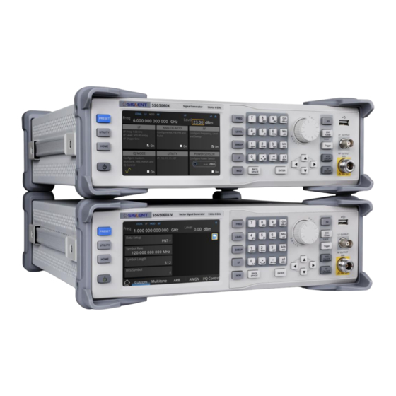
- Page 1 SSG5000X Series RF Signal Generator Quick Start EN01C...
-
Page 3: Copyright Information
Information in this publication replaces all previously corresponding material. Any method of copying, extracting, or translating the contents of this manual is not allowed without the permission of SIGLENT. Note: SIGLENT is the registered trademark of SIGLENT TECHNOLOGIES CO., LTD. SSG5000X Series Quick Start... -
Page 4: Table Of Contents
Contents Copyright Information ......................1 General Safety Summary ...................... 3 Safety Terms and Symbols ....................4 Allgemeine Sicherheitsübersicht.................... 5 Sicherheitsbegriffe und -symbole ..................7 General Care and Cleaning ....................8 General Inspection ........................ 8 Mechanical Dimensions ......................9 Preparation Before Use ....................... 10 Front Panel Introduction ...................... -
Page 5: General Safety Summary
General Safety Summary Carefully read the following safety precautions to avoid any personal injury or damage to the instrument and any products connected to it. To avoid potential hazards, please use the instrument as specified. Use the Proper Power Cord Only the power cord designed for the instrument and authorized by local government regulations should be used. -
Page 6: Safety Terms And Symbols
Safety Terms and Symbols Terms used in this product. These terms may appear in the product: DANGER Indicates direct injury or hazards that may happen. WARNING Indicates potential injury or hazards that may happen. CAUTION Indicates potential damage to the instrument or other property that may happen. Symbols used in this product. -
Page 7: Allgemeine Sicherheitsübersicht
Allgemeine Sicherheitsübersicht Lesen Sie die folgenden Sicherheitshinweise sorgfältig durch, um Verletzungen oder Schäden am Gerät und an den daran angeschlossenen Produkten zu vermeiden. Um mögliche Gefahren zu vermeiden, verwenden Sie das Gerät bitte wie angegeben. Verwenden Sie ein geeignetes Netzkabel Verwenden Sie nur das fü... - Page 8 Betreiben Sie das Gerät nicht ohne Abdeckungen Betreiben Sie das Gerät nicht, wenn Abdeckungen oder Verkleidungen entfernt sind. Betreiben Sie das Gerät nicht bei vermuteten Defekten Wenn Sie vermuten, dass das Gerät beschä digt ist, lassen Sie es vor dem weiteren Betrieb von qualifiziertem Servicepersonal überprü...
-
Page 9: Sicherheitsbegriffe Und Symbole
Sicherheitsbegriffe und Symbole Begriffe in diesem Handbuch. Diese Begriffe können in diesem Handbuch vorkommen: WARNUNG Warnhinweise weisen auf Bedingungen oder Praktiken hin, die zu Verletzungen oder zum Verlust des Lebens führen kö nnen. VORSICHT Vorsichtshinweise weisen auf Bedingungen oder Praktiken hin, die zu Schä den an diesem Produkt oder anderen Gegenstä... -
Page 10: General Care And Cleaning
General Care and Cleaning Care: Do not store or leave the instrument in direct sunshine for extended periods. To avoid damage to the instrument or probes, please do not expose them to fog, liquid, or solvents. Cleaning: Please perform the following steps to clean the instrument and probes. Disconnect the instrument from all power sources and then clean it with a soft damp cloth. -
Page 11: Mechanical Dimensions
Mechanical Dimensions Front View Side View SSG5000X Series Quick Start... -
Page 12: Preparation Before Use
Preparation Before Use Adjust the supporting feet Adjust the supporting feet appropriately and use it as a bracket to tilt the front of the RF signal generator upwards to stabilize the generator for better operation and observation of the display. Before adjusting After adjusting Connect to AC power supply... - Page 13 Use WebServer A built-in web server provides an approach to interact with the signal generator by a web browser. It doesn’t require any additional software to be installed on the computer. Set the IP address of the generator in the browser address bar, and then the user can browse and control the generator on the web.
-
Page 14: Front Panel Introduction
Front Panel Introduction 1. Function keys 6. Direction key 2. USB Host 7. Digital keyboard 3. LF output 8. Touch screen display area 4. RF output 9. Power button 5. Knob Function keys Control Keys Description Set frequency, frequency offset, phase offset and other related parameters LEVEL Set level, level offset, ALC state, flatness and other related parameters Set sweep state, step sweep, list sweep, sweep direction and other related... - Page 15 During the parameter editing process, pressing this key will clear the input of the active function area and exit the parameter input state Press this key to return to local control if previously controlling the instrument remotely When the trigger type is set to Key, press this button to perform one operation The main switch of various modulation modes ON/OFF RF signal output switch...
- Page 16 Control Keys Description Digit 0 and space bar switch In the English state, enter the special symbol !, @, #, $, %, ^, &, *. In the digital state, enter the decimal point In the digital state, enter the "-" sign. In the English state input for case switching When setting the amplitude, press this key to set the unit as dBuV.
- Page 17 Front panel key backlight Power switch Orange light constantly on indicates the instrument is in stand-by state. Green light constantly on indicates the instrument is in power on state. When the MOD ON/OFF is set to turn on the modulation, the backlight will illuminate. If modulation is off, the backlight will be dark.
-
Page 18: Rear Panel Introduction
Rear Panel Introduction AC power input terminal The RF signal source can operate with AC power from 100-240 V, 50/60 Hz or 100-120 V, 400 Hz. Please connect the RF signal source to the AC power supply with the supplied power cord. LAN interface The RF signal source can be connected to a network through the interface and remotely controlled. - Page 19 external reference source. At this point the user interface status bar shows "Ext Ref". When an external reference is lost, exceeded, or disconnected, the instrument automatically switches to the internal reference, and the screen status bar will no longer display "Ext Ref". 10 MHz OUT The [10MHz OUT] and [REF IN] connectors are commonly used to establish synchronization between multiple instruments.
- Page 20 13. PATTERN_TRIG When the IQ Arb trigger source is "Ext", the connector is used to input the external trigger signal. 14. Q_OUT Output the analog, in–phase component of I/Q modulation from the internal baseband generator when the internal IQ modulation mode is on. 15.
-
Page 21: User Interface
User Interface Prompt status bar Touch screen display area: RF frequency Display the settings under RF level each menu Prompt status bar Display LOCAL (local), or REMOTE (remote). When REMOTE is displayed, the instrument is being controlled by a remote computer and the front panel input will be locked. To unlock the front panel (enter or send “SYSTem:REMote 0”... - Page 22 RF frequency RF output frequency setting. When the sweep type is "frequency" or "frequency & amplitude", the frequency scanning progress bar is displayed. RF level RF output level setting. When the sweep type is "amplitude" or "frequency & amplitude", level scanning progress bar is displayed.
-
Page 23: Firmware Operations
Firmware Operations Check System Information Press > System Info to view the instrument's system information, including: Model Host ID Serial Number Software Version Uboot-OS Version Hardware Version Startup Times Load Option Press > Option to enter option interface. Click the drop-down box under the Install group box to choose the license type need to be installed. - Page 24 Firmware Upgrade Follow this procedure to update the instrument firmware: Download the firmware package from an official SIGLENT website www.siglentamerica.com http://www.siglent.com/ens https://www.siglenteu.com Extract and copy the .ADS file into the root directory of a USB disk. Press > Update , and select the update file. Click Recall to update the system software.
-
Page 25: Touch Operation
Touch Operation The RF signal source provides a 5-inch capacitive touch screen to support various gesture operations, including: Click on the screen parameters or menu to pop up a virtual keyboard where you can edit the parameters. Left or right slide switches menus. Up or down slides the display menu. -
Page 26: Help Information
Help Information The built-in help system provides help information for each function and menu option on the front panel. Press button and select Help . The center of the screen will pop up to help. Click to enter the corresponding directory. Remote Control The generator supports communication with compatible computers via USB, LAN or GPIB-USB interface. -
Page 27: More Information
More Information You can obtain the instrument information and installation status of all options through UTILITY menu. For more information of this product, please refer to the following manuals (you can also download them from the SIGLENT web site): SSG5000X user manual: Provides detailed introductions of the functions of this instrument. - Page 28 Headquarters: SIGLENT Technologies Co., Ltd Add: Bldg No.4 & No.5, Antongda Industrial Zone, 3rd Liuxian Road, Bao'an District, Shenzhen, 518101, China Tel: + 86 755 3688 7876 Fax: + 86 755 3359 1582 Email: sales@siglent.com Website: int.siglent.com North America: SIGLENT Technologies America, Inc...
Need help?
Do you have a question about the SSG5000 Series and is the answer not in the manual?
Questions and answers