Table of Contents
Advertisement
Quick Links
Advertisement
Table of Contents

Related Manuals for SRAM G2 Ultimate


Summary of Contents for SRAM G2 Ultimate
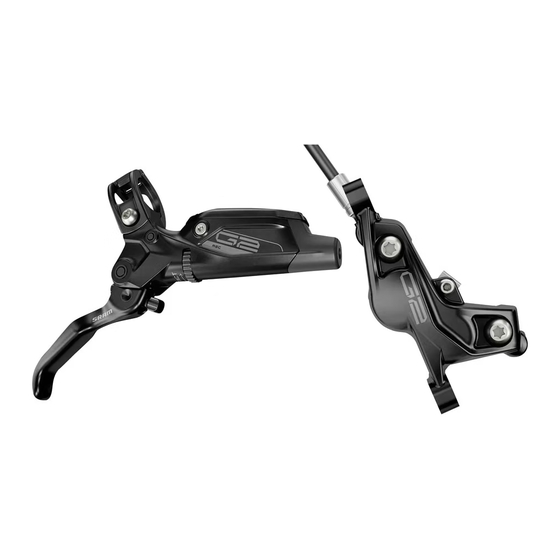
- Page 1 G2 Ultimate and RSC SERVICE MANUAL GEN.0000000005960 Rev F © 2022 SRAM, LLC...
- Page 2 This warranty applies to SRAM products made under the SRAM®, RockShox®, Truvativ®, Zipp®, Quarq®, Avid® and TIME® brand names. EXTENT OF LIMITED WARRANTY Except as otherwise set forth herein, SRAM warrants its bicycle components to be free from defects in materials or workmanship for a period of two (2) years after original purchase of the product.
- Page 3 SAFETY FIRST! We care about YOU. Please, always wear your safety glasses and protective gloves when servicing SRAM products. Protect yourself! Wear your safety gear!
-
Page 4: Table Of Contents
CALIPER PISTON REMOVAL ............................................12 CALIPER PISTON INSTALLATION ..........................................16 LEVER SERVICE .........................................19 PARTS AND TOOLS NEEDED FOR SERVICE......................................19 G2 ULTIMATE LEVER EXPLODED VIEW ........................................ 20 G2 RSC LEVER EXPLODED VIEW ..........................................20 LEVER FLUID REMOVAL .............................................. 21 LEVER BLADE REMOVAL............................................24 PISTON ASSEMBLY REMOVAL .......................................... -
Page 5: Sram G2 Brake Systems Service
SRAM brake systems need to be serviced periodically to optimize braking function. If brake fluid is leaking from any area of the brake there may be damage or wear and tear to the internal moving parts. -
Page 6: Service Procedures
S e r v i c e P r o c e d u r e s The following procedures should be performed throughout service, unless otherwise specified. Clean the part with isopropyl alcohol and a clean, lint-free shop towel. Clean the sealing surface on the part and inspect it for scratches. -
Page 7: Troubleshooting
T r o u b l e s h o o t i n g N OT ICE Do not apply DOT brake fluid or grease to caliper pistons when performing troubleshooting procedures. Use of DOT brake fluid or grease can diminish braking performance and cause rotor rubbing. - Page 8 Squeeze the brake lever to advance the pistons until they contact the rotors. Remove the rotors. Use a plastic tire lever to carefully press the pistons back into the caliper. Repeat steps 4-6 one more time. With the pistons pressed back into the caliper, install the brake pads, h-spring, pad retention bolt, and E-clip.
- Page 9 Squeeze the brake lever until the contact point is firm and lever throw is acceptable. Center the caliper on the rotor if necessary. Spin the wheel and check the brake function. The pistons should move freely and there should not be excessive brake lever throw. If there is no improvement in the brake function, proceed with caliper service.
-
Page 10: Caliper Service
DOT 5.1 or 4 brake fluid. • Pad Spacer (2.4 mm) • SRAM or AVID DOT grease. If SRAM or AVID DOT grease is not available only use a DOT compatible grease. For piston removal you will need two used brake rotors with a combined total thickness of no more than 3.7 mm. -
Page 11: Caliper Brake Pad Removal
C a l i p e r B r a k e P a d R e m o v a l Remove the brake caliper from the fork or frame. Remove the caliper mounting bracket and hardware from the caliper then set them aside in the order that they were removed. -
Page 12: Caliper Piston Removal
N OT ICE Caliper service is only required if the pistons are damaged or if the system has been contaminated with DOT 5 or mineral oil. If the calipers are operating normally, they do not require disassembly and service. Clean the calipers and install brake pads. C a l i p e r P i s t o n R e m o v a l N OT ICE DOT brake fluid will damage painted surfaces. - Page 13 Squeeze the brake lever to advance the pistons until they contact the pad spacer. Use a T25 TORX wrench to remove the banjo bolt. 2.5 mm 20 mm or 15 mm Thru Axle Remove the pad spacer. 2.5 mm Remove the pad retention bolt. Caliper Piston Removal...
- Page 14 Remove each caliper body bolt. Separate the caliper body halves. Remove both of the caliper o-rings from the inboard side of the caliper. Remove the pistons from each caliper body half. NOTI CE If it is not possible to remove the pistions by hand, soft-jawed pliers may be used to carefully remove the pistons.
- Page 15 Remove the piston seals from each caliper body half. Install new seals inside each caliper body half. ⚠ WARNI NG Do not scratch the seal gland with the pick. Scratches could cause fluid to leak when the brake is applied, which will contaminate the brake pads and could lead to a brake failure.
-
Page 16: Caliper Piston Installation
NOTI CE For the best braking performance, use only SRAM High-Performance DOT 5.1 brake fluid. If SRAM fluid is not available, use only DOT 5.1 or 4 brake fluid. Do not apply grease to the caliper piston seals. Grease on the seals will reduce the clearance between the pads and rotors when the brake is released (low pad rollback). - Page 17 Remove the o-rings from the banjo bolt and banjo fitting. DOT Grease Apply a small amount of DOT grease to the new o-rings and install them. Hold the banjo at the desired angle. Tighten the banjo bolt to 5 N·m (44.2 in-lb). 5 N·m (44.2 in-lb) Insert the bleed block into the caliper.
- Page 18 ⚠ CAUTION Servicing your brakes removes all of the fluid from the system. You must bleed the brakes after you service the brake caliper and/or lever. For brake bleed and brake hose shortening instructions, visit www.sram.com/service. Caliper Piston Installation...
-
Page 19: Lever Service
DOT 5.1 or 4 brake fluid. • Lever Pivot Bearing Press Tool- for bearing replacement • SRAM or AVID DOT grease. If SRAM or AVID DOT grease is not • SRAM Hydraulic Hose Cutter available only use a DOT compatible grease. -
Page 20: G2 Ultimate Lever Exploded View
G 2 U l t i m a t e L e v e r E x p l o d e d V i e w Reservoir bolts (2) SwingLink (red) SwingLink push rod Reservoir cap SwingLink pivot hole SwingLink SwingLink bushings (2) -
Page 21: Lever Fluid Removal
Damage to painted and/or printed surfaces by DOT brake fluid is not covered under warranty. N OT ICE G2 Ultimate lever bearing service does not require removal of DOT brake fluid from the lever. If you are only performing lever bearing service, please begin service at Lever Blade Removal... - Page 22 Remove the reservoir cap bolt nearest to the lever blade. Carefully turn the lever body upside down so that the detent spring and ball fall out of the lever body. If they do not initially fall out, gently tap the lever against a clean shop towel. Remove the remaining reservoir cap bolt.
- Page 23 Pour the fluid from the brake lever body into a pan. Remove the two bleed screws. Install new o-rings and install the bleed screws into the lever body. Separate the bladder from the reservoir cover. Spray isopropyl alcohol on the bladder and the reservoir cover and clean them with a shop towel.
-
Page 24: Lever Blade Removal
L e v e r B l a d e R e m o v a l G2 Ultimate: Use a T10 TORX wrench to remove the lever pivot bolts. G2 Ultimate G2 RSC: Place the lever pivot on top of a 6 mm socket. Tap a 4 mm hex... - Page 25 G2 RSC: Use a small flat blade screwdriver to carefully remove the G2 RSC pivot bushings. Clean the bushings and install them into the lever body. G2 RSC Lever Blade Removal...
-
Page 26: Piston Assembly Removal
P i s t o n A s s e m b l y R e m o v a l Use a T8 TORX wrench to remove the SwingLink pinch bolt. Note: The red SwingLink does not have a pinch bolt. T8 TORX 20 mm or 15 mm Thru Axle Use a T8 TORX wrench to push the SwingLink pivot pin out of the lever... - Page 27 Remove the SwingLink bushings by hand. Use a SRAM Lever Internals Assembly Tool to unthread the piston sleeve and coupler. Insert the SRAM Lever Internals Assembly Tool into the lever body and align the keyslot of the tool with the piston sleeve.
- Page 28 Place a shop towel over the lever body to prevent the piston assembly spring from forcefully ejecting. Use your hand to push out the contact adjust knob. ⚠ CAU TI O N - E YE H A ZA R D Use safety glasses.
-
Page 29: Piston Assembly Installation
Submerge the new piston assembly in SRAM High-Performance DOT brake 5.1 fluid. You can also use SRAM DOT Assembly Grease, or DOT 5.1 or 4 compatible grease, as a lubricant. SRAM High-Performance DOT brake 5.1 Fluid Install the new lubricated piston assembly into the lever body. - Page 30 Engage the slots on the sleeve with the contact adjust knob and continue to thread the SRAM Lever Internals Assembly Tool tool in a clockwise rotation until it stops. Lever Internals Assembly Tool 20 mm or 15 mm Thru Axle Use needle nose pliers to install the SwingLink bushings.
- Page 31 Black SwingLink: Adjust the length of the push rod on the SwingLink until it is extended as far as possible. Use a 2 mm hex wrench to place the pushrod into the coupler sleeve. 2 mm 2 mm Red SwingLink: Place the SwingLink pushrod into the piston. Align the holes of the SwingLink and the SwingLink bushings, then press the pivot pin into the hole until it is flush with the lever body.
- Page 32 Black SwingLink only: Apply a small amount of Loctite Threadlocker Blue 242 onto the pinch bolt. Loctite Threadlocker Blue 242 20 mm or 15 mm Thru Axle Black SwingLink only: Use a T8 TORX wrench to thread the SwingLink pinch bolt into the lever body. Use a torque wrench and a T8 TORX bit socket to torque the bolt to 1.2 N·m (10.5 in-lb).
-
Page 33: Lever Blade Installation
L e v e r B l a d e I n s t a l l a t i o n Insert the Reach Adjust Screw pin into the SwingLink cam hole. Line up the pivot holes of the lever blade with the pivot holes in the lever body. - Page 34 G2 Ultimate: Apply a small amount of Loctite Threadlocker Blue 242 onto each pivot bolt. Use a torque wrench and a T10 TORX bit socket to tighten each pivot bolt to 1.2 N·m (10.5 in-lb). G2 Ultimate Loctite Threadlocker Blue 242 G2 Ultimate 1.2 N•m (10.5 in-lb)
-
Page 35: Reservoir Cap Installation
R e s e r v o i r C a p I n s t a l l a t i o n Press the bladder into the reservoir cap, make sure the bladder is properly seated into the reservoir cap. The bladder should be flush with the cap. -
Page 36: Brake Hose Installation
Cut the hose to install a new barb and compression fitting. ⚠ ⚠ WARNI NG All SRAM brakes that use a compression fitting and hose barb must use a new SJ (Stealth-a-majig) hose barb and a new, red SJ compression fitting upon reassembly. - Page 37 Servicing your brakes removes all of the fluid from the system. You must bleed the brakes after you service the brake caliper and/or lever. For brake bleed, brake hose shortening, and brake pad replacement instructions, visit www.sram.com/service. Brake Hose Installation...
-
Page 38: Disc Brake Pad And Rotor Bed-In Procedure
(transfer layer) to the braking surface of the rotor. This transfer layer optimizes braking performance. To watch a video of the bed-in procedure, visit www.sram.com/service. -
Page 39: G2 Ultimate Lever Bearing Replacement
Unthread the bearing press bolt to remove the tools and old bearing. Discard the bearing. Repeat steps 1-3 to remove the other bearing. 20 mm or 15 mm Thru Axle Clean the lever body bearing bores. G2 Ultimate Lever Bearing Replacement... - Page 40 20 mm or 15 mm Thru Axle To continue with lever service, go to Piston Assembly Removal, page If you do not need to service your lever internals, go to Lever Blade Installation, page 31 to assemble the brake lever. G2 Ultimate Lever Bearing Replacement...
- Page 41 PowerLock®, PowerTap®, Qollector®, Quarq®, RacerMate®, Reba®, Rock Shox®, Ruktion®, Service Course®, ShockWiz®, SID®, Single Digit®, Speed Dial®, Speed Weaponry®, Spinscan®, SRAM®, SRAM APEX®, SRAM EAGLE®, SRAM FORCE®, SRAM RED®, SRAM RIVAL®, Stylo®, TIME®, Truvativ®, TyreWiz®, UDH®, Varicrank®, Velotron®, X0®, X01®, X-SYNC®, XX1®, Zipp®...
- Page 42 ASIAN HEADQUARTERS WORLD HEADQUARTERS EUROPEAN HEADQUARTERS SRAM Taiwan SRAM LLC SRAM Europe No. 1598-8 Chung Shan Road 1000 W. Fulton Market, 4th Floor Paasbosweg 14-16 Shen Kang Hsiang, Taichung City Chicago, Illinois 60607 3862ZS Nijkerk Taiwan R.O.C. U.S.A. The Netherlands...
Need help?
Do you have a question about the G2 Ultimate and is the answer not in the manual?
Questions and answers