Table of Contents
Advertisement
Advertisement
Table of Contents

Related Manuals for SRAM G2 RS


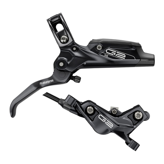
Summary of Contents for SRAM G2 RS
- Page 1 G2 RS, G2 R SERVICE MANUAL GEN.0000000006205 Rev A © 2020 SRAM, LLC...
- Page 2 LIMITATIONS OF LIABILITY To the extent allowed by local law, except for the obligations specifically set forth in this warranty statement, in no event shall SRAM or its third party suppliers be liable for direct, indirect, special, incidental, or consequential damages.
- Page 3 SAFETY FIRST! We care about YOU. Please, always wear your safety glasses and protective gloves when servicing SRAM® products. Protect yourself! Wear your safety gear!
-
Page 4: Table Of Contents
CALIPER BRAKE HOSE INSTALLATION ........................................18 LEVER SERVICE ........................................ 20 PARTS AND TOOLS NEEDED FOR SERVICE......................................20 G2 RS LEVER EXPLODED VIEW ..........................................20 G2 R LEVER EXPLODED VIEW ..........................................20 LEVER FLUID REMOVAL .............................................. 21 LEVER BLADE REMOVAL............................................24 PISTON ASSEMBLY REMOVAL .......................................... -
Page 5: Sram G2 Brake Systems Service
SRAM brake systems need to be serviced periodically to optimize braking function. If brake fluid is leaking from any area of the brake there may be damage or wear and tear to the internal moving parts. -
Page 6: Service Procedures
S e r v i c e P r o c e d u r e s The following procedures should be performed throughout service, unless otherwise specified. Clean the part with isopropyl alcohol and a clean, lint-free shop towel. Clean the part with isopropyl alcohol and a clean, lint-free shop towel. -
Page 7: Troubleshooting
T r o u b l e s h o o t i n g NOT ICE Do not apply DOT brake fluid or grease to caliper pistons when performing troubleshooting procedures. Use of DOT brake fluid or grease can diminish braking performance and cause rotor rubbing. - Page 8 Squeeze the brake lever to advance the pistons until they contact the Squeeze the brake lever to advance the pistons until they contact the rotors. rotors. Remove the rotors. Remove the rotors. Use a plastic tire lever to carefully press the pistons back into the Use a plastic tire lever to carefully press the pistons back into the caliper.
- Page 9 Squeeze the brake lever until the contact point is firm and lever throw Squeeze the brake lever until the contact point is firm and lever throw is acceptable. is acceptable. Center the caliper on the rotor if necessary. Center the caliper on the rotor if necessary. Spin the wheel and check the brake function.
-
Page 10: Caliper Service
• SRAM High-Performance DOT 5.1 brake fluid. If SRAM fluid is not available, only use DOT 5.1 or 4 brake fluid. • SRAM or AVID DOT grease. If SRAM or AVID DOT grease is not available only use a DOT compatible grease. -
Page 11: Caliper Brake Pad Removal
C a l i p e r B r a k e P a d R e m o v a l Remove the brake caliper from the fork or frame. Remove the brake caliper from the fork or frame. Remove the caliper mounting bracket and hardware from the caliper Remove the caliper mounting bracket and hardware from the caliper then set them aside in the order that they were removed. -
Page 12: Caliper Piston Removal
N OT ICE Caliper service is only required if the pistons are damaged or if the system has been contaminated with DOT 5 or mineral oil. If the calipers are operating normally, they do not require disassembly and service. Clean the calipers and install brake pads. C a l i p e r P i s t o n R e m o v a l N OT ICE DOT brake fluid will damage painted surfaces. - Page 13 Install the pad retention bolt. Install the pad retention bolt. Insert the pad spacer so that it snaps onto the pad retention bolt. Insert the pad spacer so that it snaps onto the pad retention bolt. 2.5 mm 1.85 mm pad spacer Squeeze the brake lever to advance the pistons until they contact the Squeeze the brake lever to advance the pistons until they contact the pad spacer.
- Page 14 Pull the rubber boot from the compression nut. Pull the rubber boot from the compression nut. Disconnect the brake hose from the caliper body. Disconnect the brake hose from the caliper body. 8 mm flare nut wrench Remove each caliper body bolt. Remove each caliper body bolt.
- Page 15 Remove both of the caliper o-rings from the inboard side of the caliper. Remove both of the caliper o-rings from the inboard side of the caliper. Remove the pistons from each caliper body half. Remove the pistons from each caliper body half. NOTI CE If it is not possible to remove the pistions by hand, soft-jawed pliers may be used to carefully remove the pistons.
-
Page 16: Caliper Piston Installation
NOTI CE For the best braking performance, use only SRAM High-Performance DOT 5.1 brake fluid. If SRAM fluid is not available, use only DOT 5.1 or 4 brake fluid. Do not apply grease to the caliper piston seals. Grease on the seals will reduce the clearance between the pads and rotors when the brake is released (low pad rollback). - Page 17 Insert the bleed block into the caliper. Insert the bleed block into the caliper. Bleed block Install the pad retention bolt. Install the pad retention bolt. ⚠WARNING You must bleed your brakes before reinstalling the brake pads. Installing the brake pads prior to bleeding the brakes could contaminate the brake pads and lead to a brake failure.
-
Page 18: Caliper Brake Hose Installation
You must install a new hose barb and compression fitting before connecting the hose to the caliper. SRAM Hydraulic Hose Cutter Apply DOT grease to the hose barb threads. Thread the hose barb into Apply DOT grease to the hose barb threads. Thread the hose barb into the hose until it is flush with the end of the hose. - Page 19 ⚠ CAUTION Servicing your brakes removes all of the fluid from the system. You must bleed the brakes after you service the brake caliper and/or lever. For brake bleed and brake hose shortening instructions, visit www.sram.com/service. Caliper Brake Hose Installation...
-
Page 20: Lever Service
• Hammer available, only use DOT 5.1 or 4 brake fluid. • SRAM or AVID DOT grease. If SRAM or AVID DOT grease is not available only use a DOT compatible grease. G 2 R S L e v e r E x p l o d e d V i e w... -
Page 21: Lever Fluid Removal
Install new seals and a new hose. For best results, use only SRAM High-Performance DOT 5.1 brake fluid. If SRAM fluid is not available, only use DOT 5.1 or 4 brake fluid. Lever Fluid Removal... - Page 22 Remove the reservoir cap bolts. Remove the reservoir cap bolts. Remove the reservoir cover and bladder from the lever body. Remove the reservoir cover and bladder from the lever body. Pour the fluid from the brake lever body into a pan. Pour the fluid from the brake lever body into a pan.
- Page 23 Separate the bladder from the reservoir cover. Separate the bladder from the reservoir cover. Spray isopropyl alcohol on the bladder and the reservoir cover and Spray isopropyl alcohol on the bladder and the reservoir cover and clean them with a shop towel. clean them with a shop towel.
-
Page 24: Lever Blade Removal
SwingLink cam, lever bias spring, main pivot clip, and the lever body: SwingLink cam, lever bias spring, main pivot clip, and blade assembly. blade assembly. G2 RS G2 RS G2 R G2 R Remove the pivot bushings. Clean the bushings and install them into Remove the pivot bushings. -
Page 25: Piston Assembly Removal
P i s t o n A s s e m b l y R e m o v a l Push the SwingLink pivot pin out of the lever body. Push the SwingLink pivot pin out of the lever body. 3 mm Remove the SwingLink. - Page 26 Use needle nose pliers to remove the piston assembly. Use needle nose pliers to remove the piston assembly. Needle nose pliers Piston Assembly Removal...
-
Page 27: Piston Assembly Installation
Submerge the new piston assembly in SRAM High-Performance DOT 5.1 brake fluid. DOT 5.1 brake fluid. You can also use SRAM DOT Assembly Grease, or DOT 5.1 or 4 You can also use SRAM DOT Assembly Grease, or DOT 5.1 or 4 compatible grease, as a lubricant. -
Page 28: Rs Lever Blade Installation
R S L e v e r B l a d e I n s t a l l a t i o n Use needle nose pliers to install the SwingLink bushings. Use needle nose pliers to install the SwingLink bushings. If the SwingLink bushings fall out easily, apply a small amount of DOT If the SwingLink bushings fall out easily, apply a small amount of DOT grease to the bushings to help hold them in place. - Page 29 Hold the spring and main pivot clip in place while installing the lever Hold the spring and main pivot clip in place while installing the lever blade. Insert the reach adjust screw pin into the cam hole. blade. Insert the reach adjust screw pin into the cam hole. Line up the cam and lever blade with the holes in the lever body, then Line up the cam and lever blade with the holes in the lever body, then press the pivot pin through the holes.
-
Page 30: R Lever Blade Installation
R L e v e r B l a d e I n s t a l l a t i o n Hold the spring and main pivot clip in place while installing the lever Hold the spring and main pivot clip in place while installing the lever blade. - Page 31 Line up the cam and lever blade with the holes in the lever body, then Line up the cam and lever blade with the holes in the lever body, then press the pivot pin through the holes. press the pivot pin through the holes. Use a hammer to gently tap the pivot pin into the pivot hole.
-
Page 32: Reservoir Cap Installation
R e s e r v o i r C a p I n s t a l l a t i o n Press the bladder into the reservoir cap, make sure the bladder is Press the bladder into the reservoir cap, make sure the bladder is properly seated into the reservoir cap. -
Page 33: Lever Brake Hose Installation
NOTI CE You must install a new hose barb and compression fitting before connecting the hose to the brake lever. SRAM Hydraulic Hose Cutter 3 4 5 Apply DOT grease to the hose barb threads. Thread the hose barb into Apply DOT grease to the hose barb threads. - Page 34 Servicing your brakes removes all of the fluid from the system. You must bleed the brakes after you service the brake caliper and/or lever. For brake bleed, brake hose shortening, and brake pad replacement instructions, visit www.sram.com/service. Lever Brake Hose Installation...
-
Page 35: Disc Brake Pad And Rotor Bed-In Procedure
(transfer layer) to the braking surface of the rotor. This transfer layer optimizes braking performance. To watch a video of the bed-in procedure, visit www.sram.com/service. - Page 36 PowerTap®, Qollector®, Quarq®, RacerMate®, Reba®, Rock Shox®, Ruktion®, Service Course®, ShockWiz®, SID®, Single Digit®, Speed Dial®, Speed Weaponry®, Spinscan®, SRAM®, SRAM APEX®, SRAM EAGLE®, SRAM FORCE®, SRAM RED®, SRAM RIVAL®, SRAM VIA®, Stylo®, Torpedo®, Truvativ®, TyreWiz®, Varicrank®, Velotron®, X0®, X01®, X-SYNC®, XX1®, Zed tech®, ZIPP®...
- Page 37 ASIAN HEADQUARTERS WORLD HEADQUARTERS EUROPEAN HEADQUARTERS SRAM Taiwan SRAM LLC SRAM Europe No. 1598-8 Chung Shan Road 1000 W. Fulton Market, 4th Floor Paasbosweg 14-16 Shen Kang Hsiang, Taichung City Chicago, Illinois 60607 3862ZS Nijkerk Taiwan R.O.C. U.S.A. The Netherlands...
Need help?
Do you have a question about the G2 RS and is the answer not in the manual?
Questions and answers