
Related Manuals for Moxa Technologies AIG-300 Series


Summary of Contents for Moxa Technologies AIG-300 Series
- Page 1 AIG-300 Series Hardware User’s Manual Version 1.0, September 2021 www.moxa.com/product © 2021 Moxa Inc. All rights reserved.
- Page 2 AIG-300 Series Hardware User’s Manual The software described in this manual is furnished under a license agreement and may be used only in accordance with the terms of that agreement. Copyright Notice © 2021 Moxa Inc. All rights reserved. Trademarks The MOXA logo is a registered trademark of Moxa Inc.
-
Page 3: Table Of Contents
Table of Contents Introduction ............................1-1 Model Descriptions ..........................1-2 Package Checklist ..........................1-2 Product Features ..........................1-3 Product Specifications ......................... 1-3 Hardware Introduction........................2-1 Appearance ............................2-2 AIG-301-AZU-LX ......................... 2-2 AIG-301 US, EU, AP, and CN Models ....................2-3 Dimensions ............................ -
Page 4: Introduction
With the use of the ThingsPro Proxy utility, the device provisioning process is easier than ever. Thanks to the robust OTA function, you never have to worry about system failure during software upgrades. With the secure boot function enabled, you can enable the booting process of AIG-300 Series to prevent malicious software injection. -
Page 5: Model Descriptions
AIG-300 Series HW UM Introduction Model Descriptions The AIG-300 Series includes the following models: • AIG-301-T-AZU-LX: Advanced IIoT gateway with Arm® Cortex™-A7 dual-core 1 GHz processor, 1 CAN port, 4 DIs, 4 DOs, ThingsPro Edge and Azure IoT Edge software, -40 to 85°C operating temperature AIG-301-T-US-AZU-LX: Advanced IIoT gateway with Arm®... -
Page 6: Product Features
AIG-300 Series HW UM Introduction Product Features • Simplifies data acquisition and device management via the ThingsPro Edge software. • Seamless integration with ThingsPro Edge and Azure IoT Edge enables easy, reliable, yet secure cloud connectivity. • Supports easy device-provisioning with the ThingsPro Proxy utility. -
Page 7: Hardware Introduction
LED indicators allow you to monitor device performance and quickly identify issues, and the multiple ports can be used to connect a variety of devices. The AIG-300 Series comes with a reliable and stable hardware platform that lets you devote the bulk of your time to application development. In this chapter, we provide basic information about the device’s hardware and its various components. -
Page 8: Appearance
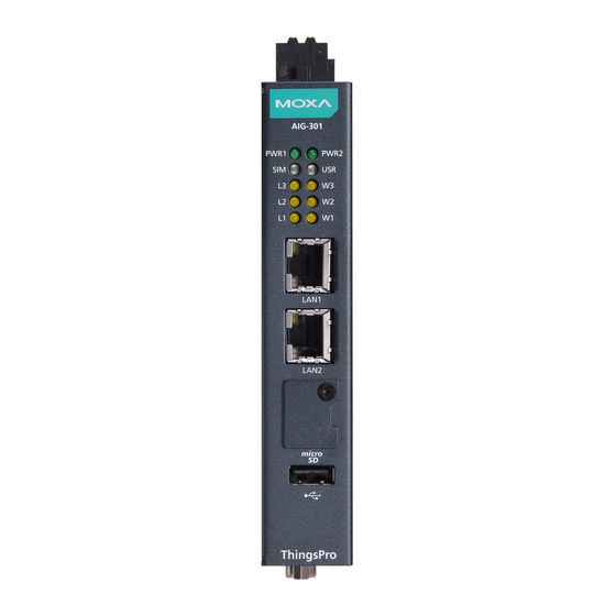
AIG-300 Series HW UM Hardware Introduction Appearance AIG-301-AZU-LX Top Panel View Front Panel View Bottom Panel View... -
Page 9: Aig-301 Us, Eu, Ap, And Cn Models
AIG-300 Series HW UM Hardware Introduction AIG-301 US, EU, AP, and CN Models NOTE The CN model does not come with the LTE module preinstalled. Contact Moxa’s distributor in China for more information. Top Panel View Front Panel View Bottom Panel View... -
Page 10: Dimensions
AIG-300 Series HW UM Hardware Introduction Dimensions AIG-301-AZU-LX AIG-301 US, EU, AP, and CN Models... -
Page 11: Led Indicators
AIG-300 Series HW UM Hardware Introduction LED Indicators The function of each LED is described in the table below: LED Name Status Function PWR1/PWR2 Green Power is on No power Green SIM2 is in use Yellow SIM1 is in use... -
Page 12: Installation Options
AIG-300 Series HW UM Hardware Introduction Installation Options DIN-rail Mounting The aluminum DIN-rail attachment plate is already attached to the product’s casing. To mount the device on to a DIN rail, make sure that the stiff metal spring is facing upwards and follow these steps. - Page 13 AIG-300 Series HW UM Hardware Introduction IMPORTANT! The diameter of the screw heads should be greater than 7 mm and less than 14 mm; the diameter of the shafts should be less than 3 mm. The length of the screws should be greater than 6 mm.
-
Page 14: Hardware Connection Description
Hardware Connection Description In this chapter, we describe how to connect the AIG-300 to a network and other devices. The following topics are covered in this chapter: Wiring Requirements Connecting the Power Grounding the Unit Connecting to the Network ... -
Page 15: Wiring Requirements
AIG-300 Series HW UM Hardware Connection Description Wiring Requirements In this section, we describe how to connect various devices to the AIG-300. Be sure to read and follow these common safety precautions before proceeding with the installation of any electronic device: •... -
Page 16: Grounding The Unit
AIG-300 Series HW UM Hardware Connection Description Grounding the Unit There is a grounding connector on the top panel of the device. Use this connector to connect a well- grounded mounting surface, such as a metal panel. Grounding and wire routing help limit the effects of noise due to electromagnetic interference (EMI). -
Page 17: Inserting The Microsd Card
AIG-300 Series HW UM Hardware Connection Description Inserting the microSD Card The device comes with a microSD socket for storage expansion. The microSD socket is located on the lower part of the front panel. To install the card, remove the screw and the protection cover to access the socket, and then insert the microSD card into the socket directly. -
Page 18: Connecting The Digital Inputs And Digital Outputs
AIG-300 Series HW UM Hardware Connection Description Connecting the Digital Inputs and Digital Outputs There are four digital inputs and four digital outputs on the top panel. Refer to the figure on the left for detailed pin definitions. Inserting the SIM Card The device comes with a SIM card socket that allows users to install two SIM cards for cellular communication. - Page 19 AIG-300 Series HW UM Hardware Connection Description Follow these steps to install the Wi-Fi module for the device. 1. Loosen the four screws on the right panel of your computer. 2. Remove the right-side cover to expose the Mini-PCIe socket.
- Page 20 AIG-300 Series HW UM Hardware Connection Description 4. Insert the wireless module card into the socket at an angle. 5. Push down the wireless module card and secure it by fastening the two black screws (M2.5x4 mm). 6. Remove the plastic protection covers on the antenna connectors.
- Page 21 AIG-300 Series HW UM Hardware Connection Description 8. Stick the insulation tape on the connectors. 9. Remove the two silver screws (M3x6 mm) and keep them for later use. 10. Fasten the two bronze screws on to the screws on the board.
-
Page 22: Connecting The Antennas
AIG-300 Series HW UM Hardware Connection Description 11. Remove the plastic sheet on the thermal pad of the heat sink, install the heat sink pad on the module, and secure the heat sink with the two silver screws (M3 x 6 mm). -
Page 23: Regulatory Approval Statements
Regulatory Approval Statements This device complies with part 15 of the FCC Rules. Operation is subject to the following two conditions: (1) This device may not cause harmful interference, and (2) this device must accept any interference received, including interference that may cause undesired operation.
Need help?
Do you have a question about the AIG-300 Series and is the answer not in the manual?
Questions and answers