Table of Contents
Advertisement
Quick Links
Advertisement
Table of Contents

Related Manuals for Vaisala WAA151


Summary of Contents for Vaisala WAA151
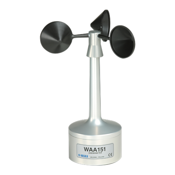
- Page 1 M210293EN-C User Guide Vaisala Anemometer WAA151...
- Page 2 Vaisala Oyj Vanha Nurmijärventie 21, FI-01670 Vantaa, Finland P.O. Box 26, FI-00421 Helsinki, Finland +358 9 8949 1 Visit our Internet pages at www.vaisala.com. © Vaisala Oyj 2018 precedence over the information No part of this document may be contained in this document.
-
Page 3: Table Of Contents
Table of Contents About This Document..................3 Version Information..................... 3 Related Manuals....................3 Documentation Conventions................3 Trademarks......................4 Product Overview....................5 Vaisala Anemometer WAA151................5 Safety........................5 2.2.1 ESD Protection....................6 Regulatory Compliances..................6 Installation......................7 Selecting Location....................7 Mounting Wind Sensors on Cross Arm............10 Connecting the Anemometer................ - Page 4 WAA151 User Guide M210293EN-C...
-
Page 5: About This Document
Vaisala Cross Arm WAC151 User Guide M210294EN Vaisala Wind Vane WAV151 User Guide M210822EN Vaisala Serial Wind Transmitter WAC155 User Guide 1.3 Documentation Conventions WARNING! Warning alerts you to a serious hazard. If you do not read and follow instructions carefully at this point, there is a risk of injury or even death. -
Page 6: Trademarks
Indicates that you need to take some notes during the task. 1.4 Trademarks Vaisalaâ is a registered trademark of Vaisala Oyj. All other product or company names that may be mentioned in this publication are trade names, trademarks, or registered trademarks of their respective owners. -
Page 7: Product Overview
+4 °C (+39 °F). 2.2 Safety The WAA151 anemometer delivered to you has been tested for safety and approved as shipped from the factory. Note the following precautions: WARNING! Ground the product and verify outdoor installation grounding periodically. -
Page 8: Esd Protection
Any modification voids your warranty. 2.2.1 ESD Protection Electrostatic Discharge (ESD) can damage electronic circuits. Vaisala products are adequately protected against ESD for their intended use. However, it is possible to damage the product by delivering electrostatic discharges when touching, removing, or inserting any objects in the equipment housing. -
Page 9: Installation
Additional protection is needed in regions with frequent, severe thunderstorms, especially when long line cables (>30 m (98 ft)) are used. Vaisala recommends using a surge protector, such as WSP150, in all sites with an elevated risk of a lightning strike. - Page 10 WAA151 User Guide M210293EN-C Figure 1 Recommended Mast Location in Open Area Any object of height (h) does not remarkably disturb wind measurement at a minimum distance of 10 × h. There must be at least 150 m (500 ft) open area in all directions from the mast.
- Page 11 Chapter 3 – Installation Figure 2 Recommended Mast Length on Top of Building The recommended minimum length (h) for the mast that is installed on the top of a building is 1.5 times the height of the building (H). When the diagonal (W) is less than the height (H) the minimum length of the mast is 1.5 ×...
-
Page 12: Mounting Wind Sensors On Cross Arm
WAA151 User Guide M210293EN-C 3.2 Mounting Wind Sensors on Cross Arm • 2-mm Allen key • Compass 1. Fit the cable plug through the mounting flange at the end of the cross arm, and connect the cable to the sensor. Plastic washer Hex screw 2. -
Page 13: Connecting The Anemometer
HTNG, 20 VDC or VAC HTNG, 20 VDC or VAC Not connected Vaisala recommends using the SOURIAU UTS6JC10E6P cable connector for the cable side of this sensor. Figure 4 WAA151 Connector Cable Side 1. Connect the heating element in the shaft tunnel between pins D and E. -
Page 14: Maintenance
WAA151 User Guide M210293EN-C 4. Maintenance 4.1 Cleaning the Anemometer Heavy contamination in the cups, such as bird droppings or ice, deteriorates the anemometer accuracy. Clean the cups when contaminated. 4.2 Testing Anemometer Operation The sensor holds its accuracy in all conditions for 1 year. If the rains are mostly casual and moderate, and the atmospheric corrosion is typical, the sensor accuracy remains for 2 years. - Page 15 Chapter 4 – Maintenance O-ring (2 pcs) Chopper disc External retaining ring, body Spacer ring Internal retaining ring, shaft Shaft and upper body assembly Cup wheel assembly Ball bearings Ball bearings Printed circuit board (PCB) Spacer (3 pcs) Lower body M6x16 DIN7991 (3 pcs) Hex nut of the connector...
-
Page 16: Reassembling The Anemometer
WAA151 User Guide M210293EN-C 1. Open the cup wheel fixing screw with a 2-mm Allen key. Remove the cup wheel assembly. CAUTION! Do not remove the fixing screw to ensure perfect sealing after reassembling. The fixing screw has been treated with sealant. - Page 17 Make sure that the bigger O-ring between the upper and lower sensor bodies is in place and fasten the three screws at the bottom of the sensor. Vaisala recommends replacing the O-ring with a new one when opening the assembly for maintenance.
-
Page 18: Troubleshooting
(200 s to 500 s). The sensor shaft is covered The heating element does not Send the sensor to Vaisala for with ice and snow. function. repair. Contact Vaisala Technical Support. -
Page 19: Technical Data
Chapter 6 – Technical Data 6. Technical Data 6.1 WAA151 Specifications Table 4 Measurement Performance Property Description/Value Sensor/Transducer type Cup anemometer/opto-chopper Observation range 0.4 … 75 m/s (0.9 … 168 mph) < 0.5 m/s (1.1 mph) Starting threshold Distance constant 2.0 m (6 ft 7 in) Transducer Output 0 …... - Page 20 WAA151 User Guide M210293EN-C Property Description/Value Heating power supply AC or DC 20 V, 500 mA nominal Settling time after power-up < 30 µs Table 6 Operating Environment Property Description/Value −50 … +55 °C (−58 … +131 °F) Operating temperature Storage temperature −60 …...
-
Page 21: Spare Parts And Accessories
Special length 6-lead heating power cable for WA15/25, open leads on ZZ45049SPEC both ends Sensor cable for WAA151/252 0.8 m (31.5 in), open lead on one end (6 ZZ45036 wires), connector 230118 on other end Sensor cable for WAV151/252 0.8 m (31.5 in), open lead on one end (10... -
Page 22: Mttr
WAA151 User Guide M210293EN-C Table 10 MTBF Values Abbreviation Installation f/106 h Permanent installations 2.34 Mobile installations 8.52 Ship equipment 5.48 6.4 MTTR Mean time to repair is 0.3 h. -
Page 23: Technical Support
If the product is faulty, these steps help to speed up the return process and avoid extra costs. 1. Read the warranty information. 2. Contact Vaisala technical support and request a Return Material Authorization (RMA) and shipping instructions. Always request the RMA before returning any faulty material. - Page 24 WAA151 User Guide M210293EN-C...
- Page 26 www. v aisala.com...
Need help?
Do you have a question about the WAA151 and is the answer not in the manual?
Questions and answers