Advertisement
Quick Links
Quick Reference Guide
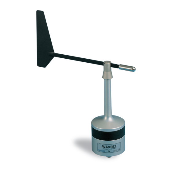
WAV252 Heated Wind Vane
Installation and Maintenance
www.vaisala.com
INSTALLATION
Initial Check
Prior to the installation check that the WAV252 is not
damaged during transportation. Check also that the shaft
rotates smoothly without any detectable noise. It is
recommended to mount the sensor body when the vane
assembly is removed. Be careful not to cause damage to the
shaft of the sensor body or to the connector pins.
Mechanical
The Heated Wind Vane WAV252 is preferably installed into
the WAC151 sensor cross arm. On bottom of the WAV252
there is a special button-shaped temperature sensor
(diameter 22 mm), elastically attached to the bottom plate.
This is for sensing the ambient temperature and should
therefore be set in good thermal contact with the mounting
support.
NOTE
The three mounting screws properly tightened
will force the temperature sensor button firmly
enough against the support.
Figure 1. Mounting of the Wind Sensor and the Hub
When installed to the WAC151 cross arm, the WAV252 is
0002-028
mounted at the northern end, the southern end is reserved
for the WAA252 Heated Anemometer.
First pre-assemble the three mounting screws, with
1.
plastic washers, to the anemometer's mounting legs.
Fit the 10-pin cable plug through the mounting flange
2.
and connect it to the sensor.
Mount the sensor to the flange by twisting, and tighten
3.
the screws.
Finally, mount the cup assembly. Align the planes in
4.
the shaft and inside the hub. The bottom edges of the
hub and the shoulder should reach approximately the
same level (see Figure 1). Tighten the set screw.
WAC151 Wiring
The wiring diagram for the WA252 system to the WAC151
Sensor Crossarm is presented in the Figure 2. The power
input wire connections are highlighted, since they differ from
those for regular wind sensors.
Figure 2. WAC151 Standard Wiring for WAA252 and WAV252
When using standard power and signal cables ZZ45049 and
ZZ45048 the connections are following:
For power supply, connect the YEL, GRN, and PNK
1.
colored wires to the screw terminal #2 and the WHT,
BRN, and GRY colored wires to the terminal #3.
For signal output connect wires GRN, YEL, WHT, VIO,
2.
0002-024
GRY, and PNK to terminals #7 ... #12. For signal
grounding, connect BLK to the terminal #5.
For the optional sensor power input connect BRN to
3.
the terminal #6.
As a power source use the Vaisala WHP25 Mains Power
Supply, which has a mast mountable, all-weather enclosure.
For a typical installation see the figure on the front page.
0002-025
Advertisement

Subscribe to Our Youtube Channel
Related Manuals for Vaisala WAV252


Summary of Contents for Vaisala WAV252
- Page 1 Finally, mount the cup assembly. Align the planes in Initial Check the shaft and inside the hub. The bottom edges of the Prior to the installation check that the WAV252 is not hub and the shoulder should reach approximately the WAV252 Heated Wind Vane same level (see Figure 1).
- Page 2 B11. Install the vane as instructed in mechanical section. CAUTION Handle the shaft carefully, do not drop Spare parts: Order number: or hit. Vane assembly for WAV252 WA35336 0002-029 A13. Remove the retaining ring (13) at the shaft. Set of bearings and gasket 16644WA Figure 3.
Need help?
Do you have a question about the WAV252 and is the answer not in the manual?
Questions and answers