Advertisement
QUICK GUIDE
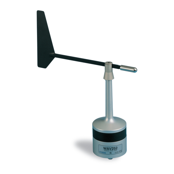
WA252 Heated Anemometer
INSTALLATION
Initial check
Before installation, check that WAA252 is not damaged during
transportation. Make sure that the shaft rotates smoothly without
any detectable noise. Vaisala recommends mounting the sensor
body when the cup assembly is removed. Be careful not to cause
damage to the shaft of the sensor body or to the connector pins.
Mounting instructions
Vaisala recommends installing the heated anemometer WAA252
onto WAC151 sensor cross arm. On bottom of WAA252 there is
a special button-shaped temperature sensor (diameter 22 mm),
elastically attached to the bottom plate. This is for sensing the
ambient temperature. Set it in good thermal contact with the
mounting support.
NOTE
The three mounting screws must be properly
tightened to force the temperature sensor button
firmly enough against the support.
Figure 1. Mounting of the wind sensor and the hub
If you use the WAC151 cross arm, mount WAA252 at the
southern end, and WAV252 Heated Wind Vane at the northern
end.
1.
Pre-assemble the 3 mounting screws with plastic washers
to the anemometer's mounting legs.
2.
Fit the 6-pin cable plug through the mounting flange and
connect it to the sensor.
3.
Mount the anemometer to the flange by twisting, and
tighten the screws.
4.
Mount the cup assembly. Align the planes in the shaft and
inside the hub. The bottom edges of the hub and the
shoulder must reach approximately the same level (see
Figure 1). Tighten the set screw.
WAC151 wiring
The wiring diagram for the WA252 system to the WAC151 sensor
cross arm is shown in Figure 2. The power input wire connections
are highlighted, since they differ from those for regular wind
sensors.
Figure 2. WAC151 standard wiring for WAA252 and WAV252
When using standard power and signal cables ZZ45049 and
ZZ45048, the connections are following:
1.
For power supply, connect the YEL, GRN, and PNK
wires to the screw terminal #2 and the WHT, BRN, and
GRY wires to the terminal #3.
2.
For signal output and grounding, connect BLU to the
terminal #1 and BLK to the terminal #5.
3.
For the optional transducer power input connect RED to
the terminal #4.
4.
For the optional power output for external transmitter
move the REDBLU spare wire to the terminal #13.
Use Vaisala WHP25 Mains Power Supply as a power source. It
has a mast-mountable, all-weather enclosure. For a typical
installation, see cover figure. WHP25 is sold as a spare part.
.
© Vaisala 2021
All rights reserved. Any logos and/or product names are trademarks of
Vaisala or its individual partners. Any reproduction, transfer, distribution or storage of
information contained in this document is strictly prohibited. All specifications —
technical included are subject to change without notice.
Advertisement
Table of Contents

Related Manuals for Vaisala WA252


Summary of Contents for Vaisala WA252
- Page 1 WA252 Heated Anemometer The wiring diagram for the WA252 system to the WAC151 sensor cross arm is shown in Figure 2. The power input wire connections Mounting instructions...
- Page 2 A13. Remove the retaining ring (13) at the shaft. Spare parts: Order number: A14. Remove the lower bearing (14). Cup assembly for WAA252 WA35066 Figure 3 WAA252 assembly Set of bearings and gasket 16644WA Power supply WHP25 WHP25 www.vaisala.com M210758EN-B...
Need help?
Do you have a question about the WA252 and is the answer not in the manual?
Questions and answers