
Subscribe to Our Youtube Channel
Related Manuals for CyberPower PDU84001


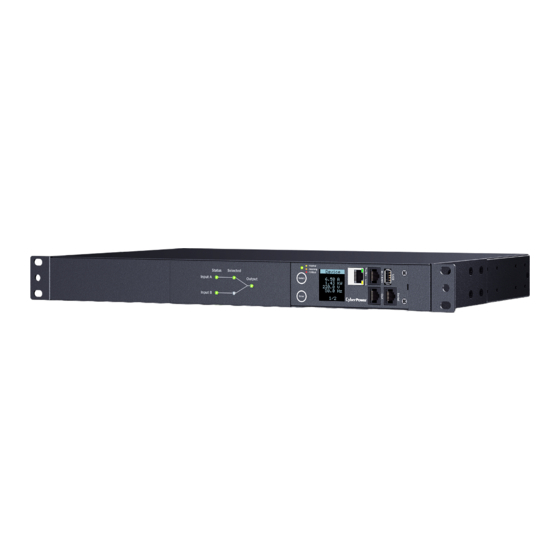
Summary of Contents for CyberPower PDU84001
- Page 1 Automatic Transfer Switch USER'S MANUAL Copyright © 2021 Cyber Power Systems, Inc. All rights reserved. K01-0000929-01...
-
Page 3: Table Of Contents
Table of Contents Overview ................. 1 Model List ................1 Safety Precautions ..............1 Product Contents ..............3 For 1U Models .....................3 For 2U Models ................... 4 Product Features ..............5 Front/Rear Panel Description (1U 15A Models) ......5 Technical Specifications .................5 Front/Rear Panel Description (1U 20A Models) ......6 Technical Specifications .................6 Front/Rear Panel Description (2U 30A Models) ......8 Technical Specifications .................8... -
Page 4: Overview
Users select the preferred source as the primary input. CyberPower Smart App Online and Sinewave series UPS are highly recommended for use as the power source. - Page 5 Before using, please check to ensure the package contains all the items shown below. If there are missing parts, please contact your local CyberPower sales team for technical support. Check Précautions de sécurité Lisez ce qui suit avant d’installer ou d’utiliser le Automatic Transfer Switches (ATS) PDU: •...
-
Page 6: Product Contents
Product Contents For 1U Models ATS PDU Mounting Bracket x 2 24 (M4x8) Bracket Mounting Screws (Includes eight spares) Cord Retention Tray 6 (M3x6) Cord Retention Tray Mounting Screws (Includes two spares) 6 (M5x12) Rack Mounting Screws/ Cable Ties 6 Washers (Includes two spares for each) Qty.: 18 (NEMA Outlet) Qty.: 30 (IEC Outlet) U s e rs... -
Page 7: For 2U Models
Product Contents For 2U Models ATS PDU Mounting Bracket x 2 24 (M4x8) Bracket Mounting Screws (Includes eight spares) Cord Retention Tray X 2 12 (M3x6) Cord Retention Tray Mounting Screws (Includes two spares for each) 6 (M5x12) Rack Mounting Screws/ Cable Ties 6 Washers (Includes two spares for each) Qty.: 30 (NEMA Outlet) -
Page 8: Product Features
AC Output Receptacles - Provides power distribution for connected equipment. Outlet Indicator (switched series only) - When the LED is on, the outlet is providing power to connected equipment. Circuit Breaker - Provides output overload protection. Technical Specifications PDU84001 PDU84004 PDU74001 PDU74004 Model Name PDU24001... -
Page 9: Front/Rear Panel Description (1U 20A Models)
Product Features Front/Rear Panel Description (1U 20A Models) Switched Metered by Outlet/ Metered by Outlet/ Switched/ Monitor Series - Normal - Warning - Critical Select Enter Metered Series - Normal - Warning - Critical Select Enter NEMA Type SOURCE A SOURCE B IEC Type Source Status Indicator - Indicates the status of Source A and B. - Page 10 Product Features Front/Rear Panel Description (1U 20A Models) Switched Metered by Outlet/ Metered by Outlet/ Switched/ Monitor Series - Normal - Warning - Critical Select Enter Metered Series - Normal - Warning - Critical Select Enter IEC Type Source Status Indicator - Indicates the status of Source A and B. Source Selected Indicator - Indicates Source A or B is in use.
-
Page 11: Front/Rear Panel Description (2U 30A Models)
Product Features Front/Rear Panel Description (2U 30A Models) Switched Metered by Outlet/ Metered by Outlet/ Switched/ Monitor Series - Normal - Warning - Critical Select Enter Metered Series - Normal - Warning - Critical Select Enter NEMA Type SOURCE A BANK 1 (20A) BANK 3... -
Page 12: Front/Rear Panel Description (2U 32A Models)
Product Features Front/Rear Panel Description (2U 32A Models) Switched Metered by Outlet/ Metered by Outlet/ Switched/ Monitor Series - Normal - Warning - Critical Select Enter Metered Series - Normal - Warning - Critical Select Enter IEC Type BANK 1 (20A) BANK 2 (20A) -
Page 13: Installation Guide
Users select the preferred source as the primary input. CyberPower Smart App Online and Sinewave series UPS are highly recommended for use as the power source. -
Page 14: Front Mounting
Installation Guide Please only use the provided screws for the entire installation process. Front Mounting For 1U Models Step 1. Mounting Bracket Installation Use the provided Mounting Bracket Screws (16) to attach the Mounting Brackets (2) to the ATS PDU. Step 2. -
Page 15: For 2U Models
Installation Guide Front Mounting Step 4. Cable Ties (Optional) Use the provided Cable Ties to fasten each cord to the Cord Retention Tray. For 2U Models Step 1. Mounting Bracket Installation Use the provided Mounting Bracket Screws (16) to attach the Mounting Brackets (2) to the ATS PDU. -
Page 16: Rear Mounting
Installation Guide Front Mounting Step 3. ATS PDU Mounting Use the provided Washers (4) and Screws (4) to secure the ATS PDU to your existing rack system. Note: You may also use the screw sets provided by the rack to secure the ATS PDU. - Page 17 Installation Guide Rear Mounting If you plan on attaching the Cord Retention Tray to the ATS PDU, use the provided Mounting Bracket Screws (8) to attach the Mounting Brackets (2) to the ATS PDU. Step 2. Cord Retention Tray Installation (optional) Adjust the length of the Cord Retention Tray till the screw hole on the Tray and ATS PDU are aligned.
-
Page 18: For 2U Models
Installation Guide Rear Mounting Step 4. Cable Ties (Optional) Use the provided Cable Ties to fasten each cord to the Cord Retention Tray. For 2U Models Step 1. Mounting Bracket Installation Use the provided Mounting Bracket Screws (16) to attach the Mounting Brackets (2) to the ATS PDU. - Page 19 Installation Guide Rear Mounting Step 2. Cord Retention Tray Installation (optional) Adjust the length of the Cord Retention Trays till the screw hole on the Trays and ATS PDU are aligned. Attach the Cord Retention Trays to the ATS PDU with the 8 supplied Cord Retention Tray Mounting Screws.
-
Page 20: Replacing Lcd Panel
Installation Guide Replacing the LCD Panel Step 1. Use a slotted screwdriver to gently lift out the LCD panel. Step 2. Disconnect the cable connector. Electrical Installation Step 1. Receptacle evaluation Ensure that the plug type of your ATS PDU unit matches the receptacles that you are using. -
Page 21: Locking Power Cord - For Iec Type Ats Pdu
Installation Guide Locking Power Cord - For IEC Type ATS PDU Input Power Cord Step 1. Align and insert the Cable Tie from the upper side of the Fixed Stand and fasten it as shown below. Step 2. Align and insert the Cable Tie from the bottom side of the Fixed Stand and fasten it as shown below. -
Page 22: Network Installation
ATS PDU, and the other end to a network port. Step 2 – Establish the ATS PDU IP address Assigning an IP address to the CyberPower ATS PDU requires the user to have an available IP address that is valid on the respective network. -
Page 23: Operation
Note: The default username is “cyber” and the default password is “cyber”. Telnet and SSH The CyberPower ATS PDU provides Telnet and Secure Shell (SSH) as Remote Management methods. Telnet uses user name and password as basic security while SSH has a higher security level with encryption of the transmitted packets including user name, password, and data. -
Page 24: Led Indicators
Outlet The outlet is off. Environmental Monitoring (optional) CyberPower ATS PDUs along with the environmental sensor (ENVIROSENSOR) provide temperature and humidity monitoring in a server closet and/or datacenter remotely. To connect the ATS PDU with ENVIROSENSOR, use the RJ45 Ethernet Cable included with the ENVIROSENSOR. -
Page 25: Firmware Upgrade
Note that the XXX is not part of the file name but is where the version number in the filename is given. Prior to performing a firmware update, please: • Download the latest firmware from www.cyberpower.com. • Extract the downloaded firmware file to your local “C:\” drive. Note: 1. - Page 26 1. Download the Upgrade and Configuration Utility from www.cyberpower.com. 2. Open Upgrade and Configuration Utility from Start > All Programs > CyberPower Upgrade and Configuration Utility. 3. Wait for search to finish (Shown in Figure 1). Figure 1 4. Check the checkbox to select devices listed in the Operation View (Shown in Figure 2).
- Page 27 Firmware Upgrade 6. Select Upgrade Firmware. 7. Click Browse to locate and select the firmware and data file to be updated (Shown in Figure 4). Figure 4 8. Click OK in the Upgrade Firmware confirmation window (Shown in Figure 5). Figure 5 9.
- Page 28 Option 3: Use a USB Flash Drive Use the following steps to upgrade the firmware. 1. Download the latest firmware from www.cyberpower.com. 2. Extract the file to the root directory of a USB flash drive with FAT32 format. • Switched Metered by Outlet/ Metered by Outlet/ Switched/ Monitored Series:...
-
Page 29: Troubleshooting
Firmware Upgrade Note: (1) The SSH setting on the ATS PDU must be Enabled. (2) <filename> is the filename of the firmware file. There are two firmware files to upload: cpsmpdumafw_XXX.bin and cpsmpdumadata_XXX.bin. In order to upgrade the firmware version both files need to be uploaded. Only one firmware file can be uploaded at a time, it is recommended to upload the firmware file cpsmpdumafw_XXX.bin first followed by the data file cpsmpdumadata_XXX.bin. -
Page 30: Conformance Approvals
Customer Service & Warranty Product Registration Thank you for purchasing a CyberPower product. Prompt product registration entitles coverage under the Limited Warranty and also allows the opportunity to be notified of product enhancements, upgrades, and other announcements. Registration is quick and easy at www.cyberpowersystems.com/registration (for USA and Canada) or www.cyberpower.com/registration (for all other regions). - Page 31 CyberPower's expense, or, if CyberPower is unable to or decides not to repair or replace the Product (if defective) within a reasonable time, CyberPower will refund to you the full purchase price you paid for the Product (purchase receipt showing price paid is required).
-
Page 32: Appendix A-Hyper Terminal
Appendix A-Hyper Terminal Hyper Terminal software can be used for basic ATS PDU configuration. In order for Hyper Terminal to interact with the ATS PDU, the PC/server must be connected directly to the ATS PDU via the serial port with the included RJ45/DB9 serial port connection cable. -
Page 33: Appendix B-Power Device Network Utility
Appendix B-Power Device Network Utility Overview The CyberPower Power Device Network Utility is an easy-to-use interface which is used for establishing IP addresses on CyberPower ATS PDUs. Installation Step 1. Download the Power Device Network Utility software from www.cyberpower.com. Step 2. Select Next in the software wizard (Shown in Figure 1). - Page 34 Getting Started The Power Device Network Utility scans the network for devices with MAC addresses that match CyberPower network hardware. Once found, the device(s) can then be figured with a specific IP address, subnet mask, and gateway address. This allows the device(s) to function properly on the network and interface with CyberPower Management Console.
- Page 35 Appendix B-Power Device Network Utility Figure 7. Windows Security Alert Step 2. Assign a valid IP Address to the ATS PDU. With the appropriate device selected from the Equipment List, open the Network Settings menu (shown in Figure 8) [Tools=>Device Setup].
-
Page 36: Appendix C-Ats Pdu Daisy-Chain Function
PDU81xxx/ 71xxx/ 41xxx/ 31xxx Appendix C-ATS PDU Daisy-Chain Function The daisy-chain function allows up to four ATS PDUs to be connected together to be monitored and controlled from one IP address. The daisy-chain function allows up to four PDUs to be connected together to be monitored and controlled from one IP address. - Page 37 Appendix C-PDU Daisy-Chain Function How to switch between Host and Guest ATS PDUs on the Web interface? Functionality supported by daisy-chained ATS PDUs will have the Host/ Guest # drop down menu displayed on the Web interface (as shown below). Can I upgrade the firmware version of the Guest ATS PDUs through the Host PDU? Yes, you can upgrade the firmware using the Upgrade and Configuration...
-
Page 38: Appendix D-Rj45/Db9 Serial Port Connection Cable Pinout
Appendix C-PDU Daisy-Chain Function Does the Host ATS PDU record the Status Records of the Guest ATS PDUs and itself? Yes, the Host ATS PDU records the Status Records for all the ATS PDUs in the daisy-chain. Will the Status Records of the Guest ATS PDUs logged in the Host ATS PDU be cleared if the Guest ATS PDUs are disconnected from the Host ATS PDU? Yes, once the Guest ATS PDUs are removed, the Status Records logged in the Host ATS PDU will be cleared. - Page 40 Cyber Power Systems, Inc. www.cyberpower.com Copyright © 2021 Cyber Power Systems, Inc. All rights reserved. K01-0000929-01...
Need help?
Do you have a question about the PDU84001 and is the answer not in the manual?
Questions and answers