Daikin BRC1H61W Installation Manual
Wired remote controller
Hide thumbs
Also See for BRC1H61W:
- Installation handbook (26 pages) ,
- Operation manual (42 pages) ,
- Operating handbook (2 pages)
Table of Contents
Advertisement
Quick Links
• Be sure to read before conducting the installation of this product, and conduct
installation according to this manual.
• Refer to this manual together with the installation manual of the indoor unit.
It is possible to perform settings of some functions from
a smart phone app.
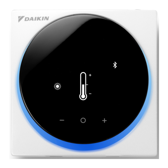
Wired Remote
Controller
Installation Manual
MODEL BRC1H61W/BRC1H61K
Advertisement
Table of Contents

Related Manuals for Daikin BRC1H61W


Summary of Contents for Daikin BRC1H61W
- Page 1 Wired Remote Controller Installation Manual MODEL BRC1H61W/BRC1H61K • Be sure to read before conducting the installation of this product, and conduct installation according to this manual. • Refer to this manual together with the installation manual of the indoor unit.
-
Page 2: Table Of Contents
Contents Safety Precautions ............. 2 Accessories ................ 3 Remote controller installation procedure ......4 Button Locations and Descriptions ........11 Overview of screens ............12 Setting screen list ............. 13 Names and Functions ............15 Starting up the system ............16 Switching the Changeover Master ........ -
Page 3: Safety Precautions
Safety Precautions „ Also refer to installation manual attached to the indoor unit. „ Please read these “Safety Precautions” carefully before installing the remote controller. • This manual classifies the precautions into WARNINGS and CAUTIONS. Be sure to follow all the precautions below: They are all important for ensuring safety. Indicates a potentially hazardous situation which, if not avoided, could WARNING result in death or serious injury. -
Page 4: Accessories
CAUTION To avoid electric shocks due to entry of water or insects, fill the wiring through hole with putty. Do not operate with wet hands to avoid electric shocks. Do not wash the remote controller with water. It may result in electric shocks or a fire. Install the air conditioner, power supply wiring, remote controller wiring and transmission wiring at least 1 meter away from televisions or radios to prevent image interference or noise. -
Page 5: Remote Controller Installation Procedure
Remote controller installation procedure Deciding where to install the remote controller Select the installation location based on “Safety Precautions” (see page 2) and obtain consent of the customer. Creating a wiring through-hole in the wall (when opening a hole in the wall and installing) [Unit : inch (mm)] 3-11/64 (80.5) Back plate... - Page 6 Determining the wire routing direction for the back plate Before mounting the controller, determine the wiring direction and remove a piece of the controller’s back plate accordingly (i.e.: a, b, c). The wiring can be routed from the top, the left, or the bottom of the back cover.
- Page 7 Securing the back plate Wall installation 1 : Take the cross recessed round head wood screws and drywall anchors out of the accessory bag. 2 : Mount the back plate to a flat surface. Drywall anchors Cross recessed round head wood screws CAUTION •...
- Page 8 Connecting the electrical wiring All wiring must comply with the following requirements: Wire specification Value Wiring type Non-shielded, 2-conductor, Stranded copper wire Wiring size AWG-18 Wiring length Maximum 1640 feet (500 m) Prepare the wiring for connection to the remote controller following these instructions: Approx.
- Page 9 Top outlet P1P2 P1P2 terminal Rear outlet P1P2 Left outlet P1P2...
- Page 10 Bottom outlet P1P2 CAUTION • Keep the wiring away from the power wire so that electrical noise (external noise) is not received. • In order to prevent the entry of water or insects, use putty (field supply) to securely seal the wiring lead-in hole.
- Page 11 When removing the upper casing Insert a flat head screwdriver into the recess in the back plate and remove the upper casing. (2 locations) CAUTION • The remote controller circuit board is attached to the upper casing. Be careful not to damage the circuit board and casing when removing the upper casing.
-
Page 12: Button Locations And Descriptions
Button Locations and Descriptions Functions items (i.e., Operation Mode, Fan Speed, and Setpoint) are set from the menu screen. NOTICE • Do not install the remote controller in places exposed to direct sunlight. The LCD may be damaged. • Do not pull or twist the remote controller cord. The remote controller may be damaged. •... -
Page 13: Overview Of Screens
Overview of screens How to display the screen The following is just an example. The items available for setting vary depending on the indoor unit you are using. If there is no button operation for about 10 seconds, the screen returns to the home screen. -
Page 14: Setting Screen List
Setting screen list Setting list Installer User Administrator menu menu menu Icon Name Description Depends on Operation Mode Operation mode setting current setting Depends on Fan Speed Airflow rate setting current setting Depends on Airflow Direction Airflow direction 1 setting ... - Page 15 Setting list Installer User Administrator menu menu menu Icon Name Description Bluetooth Setting Bluetooth setting Backlight Backlight brightness setting Contrast Contrast setting Clock Setting Clock setting About Administrator information Administrator password Admin Password ...
-
Page 16: Names And Functions
Bluetooth SIG, Inc. and use q Information icon of such marks by Daikin industries, LTD. is under r Settings menu icon license. Other trademarks and trade names are those of their respective owners. -
Page 17: Starting Up The System
Starting up the system • Check for completion of indoor/outdoor unit wiring. • Ensure that covers is closed on electrical component boxes for both indoor and outdoor units prior to restoring power. Power-on • The controller gets its power from the indoor unit. •... - Page 18 INFORMATION When digital input adapter BRP7A5* is part of the system, it is not possible to connect a second controller. Connecting a second controller when the system already contains the adapter will cause the adapter to go into error mode. INFORMATION If a sub controller does not display the home screen 2 minutes after its designation, turn off the power and check the wiring.
- Page 19 Designating a controller as main or sub Prerequisite: A remote controller is already connected to the indoor unit. Connect a second controller. After turning on the power, perform setting of the second controller. Result: It will start up automatically. Home screen Wait for a U5 or U8 error code to appear on the screen.
-
Page 20: Switching The Changeover Master
Switching the Changeover Master About the changeover master When multiple indoor units are connected to one outdoor unit or branch selector unit, by giving the authority to switch the operation mode to a specific indoor unit, the operation switching of other indoor units can be controlled. •... - Page 21 Heat pump system When multiple indoor units are connected to 1 outdoor unit: Give the authority to choose cooling, heating, or auto to 1 of these remote controllers. a Outdoor unit b Indoor unit c Remote controller d Changeover master e Changeover mode follower •...
- Page 22 Releasing the changeover master (VRV only) To change the authority to choose cooling/heating, you must first specify the remote controller with the authority, then release the authority. Depending on the system, setting may not be available. Prerequisite: You are in the installer menu. You are operating the controller of the indoor unit that you want to release from being the changeover master.
- Page 23 Sub-menu screen Press to release the indoor unit from its authority. Result: • The indoor unit is released from its authority. • The controllers of all indoor units display a blinking “ ” icon. Setting up the changeover master This setting is available only when none of the remote control in the system has master control.
-
Page 24: Installer Menu
Sub-menu screen Result: • The indoor unit is now the changeover master (“ ” icon not displayed). • All sub controllers display the “ ” icon. Installer Menu How to enter the Installer menu Installer menu screen Home screen Press and hold button for 5 seconds or longer to display the information screen. -
Page 25: Field Setting
Field Setting Field settings method This section describes how to perform field setting. Refer to page 23 and enter the installer menu. Installer menu screen Press button, for move to “ ”. If Bluetooth is connected, performing field setting from the remote controller side is impossible. - Page 26 Sub-menu screen Press button, scroll to the desired Unit No. and Mode 20 then press button to set the selection. Unit 00 Sub-menu screen Press button, to select “ ”, and then press Mode 20 button to set the selection. Unit 00 Sub-menu screen Press...
- Page 27 Sub-menu screen Press button, to move Second Code No., and SW 00 then press button. – 01 Sub-menu screen Press button, to scroll to the desired Second SW 00 Code No., and then press button. – 01 Sub-menu screen Press button, select “...
- Page 28 CAUTION • The connection of optional accessories to the indoor unit might cause changes to some field settings. For more information, see the installation manual of the optional accessory. • For details about the specific field settings of each type of indoor unit, see the installation manual of the indoor unit.
- Page 29 NOTICE • Installation of optional accessories on the indoor unit may require changes to field settings. See the manual of the optional accessory. • For field setting details related to the indoor unit, see installation manual shipped with the indoor unit. Field setting mode list SECOND CODE NO.
- Page 30 SECOND CODE NO. (Note 2) Mode FIRST (Items in bold are factory default settings) CODE Description (Note 1) High ceiling setting (Setting for when installed in ceiling higher than 2.7 m). 2.7 m<, 3.0 m<, * Height depends on the ≤2.7 m ≤3.0 m ≤3.5 m —...
- Page 31 Notes) 1. Though setting is performed totally in the group, set Mode No. in the parenthesis when individual setting per indoor unit or checking after the setting should be performed. 2. SECOND CODE NO. at factory shipment is set to “01”. However for the following cases it is not “01”.
-
Page 32: R/C Setting
R/C Setting R/C setting method This section describes how to perform R/C setting. Refer to page 23 and enter the installer menu. Installer menu screen Press button, move to “ ”. If Bluetooth is connected, performing field setting from the remote controller side is impossible. Disconnect Bluetooth, or perform field setting from the mobile application. - Page 33 Sub-menu screen Press button, select First Code No., and then SW 03 press button. a First Code No. – 00 b Second Code No. Sub-menu screen Press button, scroll to the desired First code SW 13 No. and then press button to set the selection.
- Page 34 Sub-menu screen Press button, select “ ”, and then button to SW 13 save the setting and return to the previous screen. If the setting is not changed, select “ ”. – 00 Sub-menu screen Press button, move to “ ”, and then press Mode R3 button to return to the installer menu.
-
Page 35: Installer Password Setting
Installer Password Setting Installer password setting method This section describes how to perform password setting. Refer to page 23 and enter the installer menu. Installer menu screen Press button, for move to “ ”. If Bluetooth is connected, performing field setting from the remote controller side is impossible. -
Page 36: Other Service Settings
Sub-menu screen Press button, set any password, and then press button. Each time button is pressed, the digit place will 0 0 0 0 change. When the 4th digit on the right end is reached, press button to return to the previous screen. Sub-menu screen Press button, select “... -
Page 37: External Input Interlock
External input interlock About external input interlock External input interlock allows for the integration of key card and window contact logic into the system. External input interlock is only available in case digital input adapter BRP7A5* is part of the system. When the adapter is part of the system: •... - Page 38 External input interlock settings overview Parameter Description Possible values Default value Timer that starts as soon 0-10 minutes “1 min” B2 Delay Timer as the key card is removed. The unit continues normal operation until the timer expires. B2 Reset Timer Timer that starts as soon 0-20 hours “20 hours”...
- Page 39 Parameter Description Possible values Default value Reset Heat SP “Default Reset Setting” See indoor unit’s “22°C” heating setpoint setpoint range and setpoint range limitation, “--” INFORMATION When the value for a parameter is “- -”, this means that when the timers expires, nothing changes for that parameter and the current active value is kept.
- Page 40 Key card contact logic Window contact B1 Key card contact B2 Time Action Contact closed Contact closed • — • The unit operates (window closed) (key card IN) • Delay timer<Time normally. <Reset timer • If the reset timer has not •...
- Page 41 Combination of window contact and key card contact logic • The window contact has priority over the delay timer and the Setback functionality of the key card contact: When the window contact is opened while the key card contact is open, the delay timer will immediately expire if it is still running, and Setback will not work anymore.
- Page 42 Example 2 1 : You open the window. Result: The unit stops immediately. It is not possible to turn the unit on or off with the ON/OFF button, the Setback functionality does not work, and the delay timer does not start counting.
-
Page 43: License
License The following OSS is included in the remote controller. [micro-ecc] Copyright (c) 2014, Kenneth MacKay All rights reserved. Redistribution and use in source and binary forms, with or without modification, are permitted provided that the following conditions are met: * Redistributions of source code must retain the above copyright notice, this list of conditions and the following disclaimer. -
Page 44: Certification
Certification COMPLIANCE WITH REGULATIONS • In India For model: BRC1H61W ETA-SD-20200603421 For model: BRC1H61K ETA-SD-20200603679 • In Malaysia For model: BRC1H61W For model: BRC1H61K SQASI/TA/20/1972 SQASI/TA/20/1973 • In Philippines For model: BRC1H61W For model: BRC1H61K ESD-2022264C ESD-RCE-2022819 • In Singapore... - Page 45 • In Thailand • In Vietnam For model: BRC1H61W Certificate of conformity number: 283/CN-TT2 For model: BRC1H61K Certificate of conformity number: 280/CN-TT2 • In Australia • In New Zealand...
- Page 46 EM19A034 [2009] HT...
Need help?
Do you have a question about the BRC1H61W and is the answer not in the manual?
Questions and answers