Daikin BRC1H61W Installation Handbook
Wired remote controller
Hide thumbs
Also See for BRC1H61W:
- Operation manual (42 pages) ,
- Installation manual (46 pages) ,
- Operating handbook (2 pages)
Advertisement
Quick Links
Wired Remote
Controller
Installation Handbook
MODEL BRC1H61W/BRC1H61K
• Be sure to read before conducting the installation
of this product, and conduct installation according
to this manual.
• Refer to this manual together with the installation
manual of the indoor unit.
• It is possible to perform settings of some functions
from a smart phone app.
• For details, refer to the BRC1H61W/BRC1H61K
manual on our company website.
Advertisement

Related Manuals for Daikin BRC1H61W


Summary of Contents for Daikin BRC1H61W
- Page 1 • Refer to this manual together with the installation manual of the indoor unit. • It is possible to perform settings of some functions from a smart phone app. • For details, refer to the BRC1H61W/BRC1H61K manual on our company website.
-
Page 2: Table Of Contents
Contents Safety Precautions ............. 2 Accessories ................ 3 Button Locations and Descriptions ........4 Remote controller installation procedure ......6 Field Setting ..............17 License ................20 Certification ..............21... -
Page 3: Safety Precautions
Safety Precautions „ Also refer to installation manual attached to the indoor unit. „ Please read these “Safety Precautions” carefully before installing the remote controller. • This manual classifies the precautions into WARNINGS and CAUTIONS. Be sure to follow all the precautions below: They are all important for ensuring safety. Indicates a potentially hazardous situation which, if not avoided, could WARNING result in death or serious injury. -
Page 4: Accessories
CAUTION To avoid electric shocks due to entry of water or insects, fill the wiring through hole with putty. Do not operate with wet hands to avoid electric shocks. Do not wash the remote controller with water. Failure to do so many cause electric shock or a fire. Install the air conditioner, power supply wiring, remote controller wiring and transmission wiring at least 1 meter away from televisions or radios to prevent image interference or noise. -
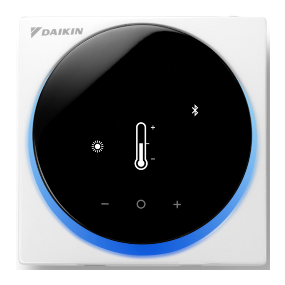
Page 5: Button Locations And Descriptions
Button Locations and Descriptions Functions items (i.e., Operation Mode, Fan Speed, and Setpoint) are set from the menu screen. NOTICE • Do not install the remote controller in places exposed to direct sunlight. The LCD may be damaged. • Do not pull or twist the remote controller cord. The remote controller may be damaged. •... - Page 6 Information icon owned by the Bluetooth SIG, Inc. and use of such marks by r Settings menu icon Daikin industries, LTD. is under license. Other trademarks and trade names are those of their respective owners. INFORMATION Depending on the connected model, some items may not be displayed.
-
Page 7: Remote Controller Installation Procedure
Remote controller installation procedure Deciding where to install the remote controller Select the installation location based on “Safety Precautions” (see page 2) and obtain consent of the customer. Creating a wiring through-hole in the wall (when opening a hole in the wall and installing) [Unit : inch (mm)] 3-11/64 (80.5) Back plate... - Page 8 Determining the wire routing direction for the back plate Before mounting the controller, determine the wiring direction and remove a piece of the controller’s back plate accordingly (i.e.: a, b, c). The wiring can be routed from the top, the left, or the bottom of the back cover.
- Page 9 Securing the back plate Wall installation 1 : Take the cross recessed round head wood screws and drywall anchors out of the accessory bag. 2 : Mount the back plate to a flat surface. Drywall anchors Cross recessed round head wood screws CAUTION •...
- Page 10 Connecting the electrical wiring All wiring must comply with the following requirements: Wire specification Value Wiring type Non-shielded, 2-conductor, Stranded copper wire Wiring size AWG-18 Wiring length Maximum 1640 feet (500 m) Prepare the wiring for connection to the remote controller following these instructions: Approx.
- Page 11 Top outlet P1P2 P1P2 terminal Rear outlet P1P2 Left outlet P1P2...
- Page 12 Bottom outlet P1P2 CAUTION • Keep the wiring away from the power wire so that electrical noise (external noise) is not received. • In order to prevent the entry of water or insects, use putty (field supply) to securely seal the wiring lead-in hole.
- Page 13 When removing the upper casing Insert a flat head screwdriver into the recess in the back plate and remove the upper casing. (2 locations) CAUTION • The remote controller circuit board is attached to the upper casing. Be careful not to damage the circuit board and casing when removing the upper casing.
- Page 14 Designating a controller as main or sub Prerequisite: A remote controller is already connected to the indoor unit. Connect a second controller. After turning on the power, perform setting of the second controller. Result: It will start up automatically. Home screen Wait for a U5, U8 error code to appear on the screen.
- Page 15 Releasing the changeover master (VRV only) To change the authority to choose cooling/heating, you must first specify the remote controller with the authority, then release the authority. Depending on the system, setting may not be available. Prerequisite: You are in the installer menu. You are operating the controller of the indoor unit that you want to release from being the changeover master.
- Page 16 Sub-menu screen Press to release the indoor unit from its authority. Result: • The indoor unit is released from its authority. • The controllers of all indoor units display a blinking “ ” icon.
- Page 17 Setting up the changeover master This setting is available only when none of the remote control in the system has master control. Prerequisite: No indoor unit is yet set as the changeover master (“ ” icon blinking on all controllers). You are operating the controller of the indoor unit that you want to set as the changeover master.
-
Page 18: Field Setting
Field Setting Field settings method This section describes how to perform field setting. Home screen Press and hold button for 5 seconds or longer to display the information screen. ˚C Information screen Press (in that order) and hold them down ... - Page 19 Sub-menu screen Press button, to select Unit No. and press Mode 20 button. Press button, scroll to the desired Unit No. and Unit 00 then press button to set the selection. Sub-menu screen Press button, to select , and then press Mode 20 button to set the selection.
- Page 20 Sub-menu screen Press button, select , and then press SW 00 button to fix the setting and return to the previous screen. – 01 If the setting is not changed, select Sub-menu screen Press button, move to , and then press Mode 20 button to return to the installer menu.
-
Page 21: License
License The following OSS is included in the remote controller. [micro-ecc] Copyright (c) 2014, Kenneth MacKay All rights reserved. Redistribution and use in source and binary forms, with or without modification, are permitted provided that the following conditions are met: * Redistributions of source code must retain the above copyright notice, this list of conditions and the following disclaimer. -
Page 22: Certification
Certification COMPLIANCE WITH REGULATIONS • In India For model: BRC1H61W ETA-SD-20200603421 For model: BRC1H61K ETA-SD-20200603679 • In Malaysia For model: BRC1H61W For model: BRC1H61K SQASI/TA/20/1972 SQASI/TA/20/1973 • In Philippines For model: BRC1H61W For model: BRC1H61K ESD-2022264C ESD-RCE-2022819 • In Singapore... - Page 23 • In Thailand • In Vietnam For model: BRC1H61W Certificate of conformity number: 283/CN-TT2 For model: BRC1H61K Certificate of conformity number: 280/CN-TT2 • In Australia • In New Zealand...
- Page 26 3P607378-2B EM19A036A [2007] HT...
Need help?
Do you have a question about the BRC1H61W and is the answer not in the manual?
Questions and answers