Advertisement

DIAGNOSTIC MANUAL
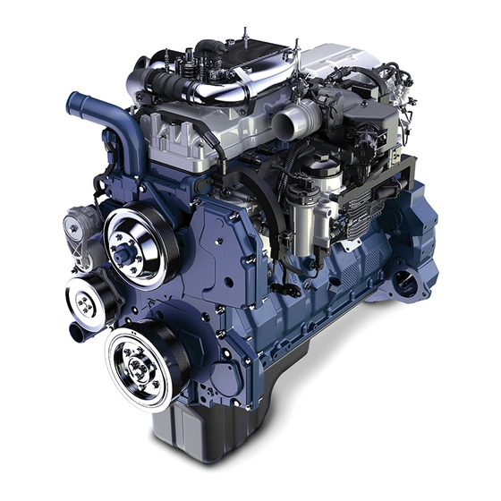
N9 and N10 Engine
Navistar, Inc.
2701 Navistar Drive, Lisle, IL 60532 USA
© 2014 Navistar, Inc. All rights reserved. All marks are trademarks of their respective owners.

Advertisement

Table of Contents
loading

Summary of Contents for Navistar N9

  • Page 1 DIAGNOSTIC MANUAL N9 and N10 Engine Navistar, Inc. 2701 Navistar Drive, Lisle, IL 60532 USA © 2014 Navistar, Inc. All rights reserved. All marks are trademarks of their respective owners.
  • Page 3 DIAGNOSTIC MANUAL TABLE OF CONTENTS Foreword........................1 Service Diagnosis .
  • Page 4 DIAGNOSTIC MANUAL...
  • Page 5 DIAGNOSTIC MANUAL Foreword Navistar, Inc. is committed to continuous research and development to improve products and introduce technological advances. Procedures, specifications, and parts defined in published technical service literature may be altered. NOTE: Photo illustrations identify specific parts or assemblies that support text and procedures; other areas in a photo illustration may not be exact.
  • Page 6 DIAGNOSTIC MANUAL Service Diagnosis Service diagnosis is an investigative procedure that must be followed to find and correct an engine application problem or an engine problem. If the problem is engine application, see specific vehicle manuals for further diagnostic information. If the problem is the engine, see specific Engine Diagnostic Manual for further diagnostic information.
  • Page 7 DIAGNOSTIC MANUAL Safety Information This manual provides general and specific maintenance procedures essential for reliable engine operation and your safety. Since many variations in procedures, tools, and service parts are involved, advice for all possible safety conditions and hazards cannot be stated. Read safety instructions before doing any service and test procedures for the engine or vehicle.
  • Page 8 DIAGNOSTIC MANUAL • Clear the area before starting the engine. Engine • The engine should be operated or serviced only by qualified individuals. • Provide necessary ventilation when operating engine in a closed area. • Keep combustible material away from engine exhaust system and exhaust manifolds. •...
  • Page 9 DIAGNOSTIC MANUAL • Check for frayed power cords before using power tools. Fluids Under Pressure • Use extreme caution when working on systems under pressure. • Follow approved procedures only. Fuel • Do not over fill the fuel tank. Over fill creates a fire hazard. •...
  • Page 10 DIAGNOSTIC MANUAL...
  • Page 11: Table Of Contents

    1 DIAGNOSTIC TROUBLESHOOTING PROCEDURES Table of Contents Diagnostic Trouble Code (DTC’s) List................11 Operational Checkout Procedures.
  • Page 12 1 DIAGNOSTIC TROUBLESHOOTING PROCEDURES 7.1 - Lube Oil Contamination................107 7.2 - Lube Oil to Coolant.
  • Page 13 1 DIAGNOSTIC TROUBLESHOOTING PROCEDURES DEF: TL & DEF: TT (Diesel Exhaust Fluid Tank Level and Temperature) Sensor Module..746 DEF: SMH Relay (Diesel Exhaust Fluid Supply Module Heater Relay) ......782 DOC Temperature Sensor Module.
  • Page 14 1 DIAGNOSTIC TROUBLESHOOTING PROCEDURES...
  • Page 15: Diagnostic Trouble Code (Dtc's) List

    1 DIAGNOSTIC TROUBLESHOOTING PROCEDURES Diagnostic Trouble Code (DTC’s) List Sub-section Condition Description EGR (page 1074) EGRP fault: over temperature EGR (page 1074) EGR internal circuit failure ETP (page 1187) ETP signal Out of Range HIGH ETP (page 1187) ETP signal Out of Range LOW ETP (page 1187) ETP does not agree with commanded position APP (page 402)
  • Page 16 1 DIAGNOSTIC TROUBLESHOOTING PROCEDURES Sub-section Condition Description EWPS(page 1210) Engine Cooling System above Critical Temperature ECT1 (page 1033) ECT1 signal erratic, intermittent, or incorrect ECT1 (page 1033) ECT1 signal Out of Range HIGH ECT1 (page 1033) ECT1 signal Out of Range LOW EWPS (page 1210) Engine Cooling System above Warning Temperature EWPS (page 1210)
  • Page 17 1 DIAGNOSTIC TROUBLESHOOTING PROCEDURES Sub-section Condition Description EGT (page 1115) EGT signal Out of Range LOW EOT (page 1163) EOT signal erratic, intermittent, or incorrect EOT (page 1163) EOT signal Out of Range HIGH EOT (page 1163) EOT signal Out of Range LOW EOT (page 1163) EOT not warming along with engine EWPS (page 1210)
  • Page 18 1 DIAGNOSTIC TROUBLESHOOTING PROCEDURES Sub-section Condition Description INJ (page 1365) Injector 2 Spool Motion Compensation Max Authority Reached INJ (page 1365) Injector 2 Fuel quantity / timing error INJ (page 1365) Injector 3 open coil - short circuit INJ (page 1365) Injector 3 open coil - open circuit INJ (page 1365) Injector 3 Spool Motion Compensation Max Authority...
  • Page 19 1 DIAGNOSTIC TROUBLESHOOTING PROCEDURES Sub-section Condition Description 1173 TC2CIT (page 1978) TC2CIT signal above desired (Low Pressure CAC Interstage under cooling) 1189 TC2WC (page 1997) TC2WC short to PWR 1189 TC2WC (page 1997) TC2WC Open or short to GND 1209 AMS (page 381) EBP above desired level 1209...
  • Page 20 1 DIAGNOSTIC TROUBLESHOOTING PROCEDURES Sub-section Condition Description 2659 AMS (page 381) EGR Slow Response Fault 2659 AMS (page 381) EGR System flow rate error during Air Management Test 2659 AMS (page 381) EGR High Flow Rate detected 2659 AMS (page 381) EGR Low Flow Rate detected 2791 EGR (page 1074)
  • Page 21 1 DIAGNOSTIC TROUBLESHOOTING PROCEDURES Sub-section Condition Description 3242 DPFIT (page 876) DPFIT signal Out of Range HIGH 3242 DPFIT (page 876) DPFIT signal Out of Range LOW 3242 DPFIT (page 876) DPFIT above Warning Temperature 3242 DPFIT (page 876) DPFIT above Maximum Temperature 3246 DPFOT (page 898) DPFOT above Critical Temperature...
  • Page 22 1 DIAGNOSTIC TROUBLESHOOTING PROCEDURES Sub-section Condition Description 3482 AFTFSV (page 205) AFT Fuel Enable Control Valve short to PWR 3482 AFTFSV (page 205) AFT Fuel Enable Control Valve open or short to GND 3509 VREF (page 2025) VREF 1 voltage above maximum 3509 VREF (page 2025) VREF 1 voltage below minimum...
  • Page 23 1 DIAGNOSTIC TROUBLESHOOTING PROCEDURES Sub-section Condition Description 3936 EWPS (page 1210) DPF Soot Load – Severe De-Rate 3936 AFT (page 156) DOC/DPF Temperature module (Incorrect Part) 3936 AFT (page 156) DPF System above Warning Pressure 3936 AFT (page 156) DPF System above Maximum Pressure 4077 AFTFP2 (page 257) AFTFP2 signal Out of Range HIGH...
  • Page 24 1 DIAGNOSTIC TROUBLESHOOTING PROCEDURES Sub-section Condition Description 4360 SCRIT (page 1954) SCRIT signal Out of Range HIGH 4360 SCRIT (page 1954) SCRIT signal Out of Range LOW 4360 SCRIT (page 1954) SCRIT above Maximum Temperature 4363 SCROT (page 1968) SCROT above Critical Temperature 4363 SCROT (page 1968) SCROT signal erratic, intermittent or incorrect...
  • Page 25 1 DIAGNOSTIC TROUBLESHOOTING PROCEDURES Sub-section Condition Description 5109 DCU (page 475) DCU battery voltage below 10 volts 5109 DCU (page 475) DCU not detected on J1939 5246 DEFTLT (page 746) SCR Tamper Proof Inducement Level 1 status 5298 AFT (page 156) DOC Efficiency fault, Temperature below minimum Regen Aborted 5298...
  • Page 26 1 DIAGNOSTIC TROUBLESHOOTING PROCEDURES Sub-section Condition Description 5743 SCR (page 1907) SCR Thermocouple Controller signal erratic, intermittent, or incorrect 5743 SCR (page 1907) SCR Thermocouple Controller above Maximum Temperature 5743 SCR (page 1907) SCR Temperature module not detect J1939 5745 DEFSMH (page 508) DEF Supply Module Heater Out of Range HIGH 5745...
  • Page 27: Operational Checkout Procedures

    1 DIAGNOSTIC TROUBLESHOOTING PROCEDURES Operational Checkout Procedures 1.0 - Preliminary Vehicle Operational Checkout Procedure Step 1 Inspect fuel level, quality, and fuel system. Decision Perform Fuel Level Inspection (page 2352), Fuel System Inspection (page 2349), and Yes: Go to Step 2. Fuel Quality Inspection (page 2350).
  • Page 28 1 DIAGNOSTIC TROUBLESHOOTING PROCEDURES Step 5 Inspect engine oil level. Decision Perform Engine Oil Level Inspection (page 2353). Yes: Go to Step 6. Is engine oil level to specification? No: Correct engine oil level problem. After repairs are complete, retest for original problem.
  • Page 29 1 DIAGNOSTIC TROUBLESHOOTING PROCEDURES Step 8 Review Repair Order (RO) and operator complaint. Go to operational checkout procedure for specific symptom: • 2.0 Engine Does Not Start Operational Checkout Procedure (page 26) • 3.0 Engine Hard to Start Operational Checkout Procedure (page 30) •...
  • Page 30: Engine Does Not Start Operational Checkout Procedure

    1 DIAGNOSTIC TROUBLESHOOTING PROCEDURES 2.0 - Engine Does Not Start Operational Checkout Procedure Overview The following steps direct technicians to systematically troubleshoot engine no start conditions and avoid unnecessary repairs.
  • Page 31 1 DIAGNOSTIC TROUBLESHOOTING PROCEDURES Step 1 Perform preliminary operational checkout procedure. Decision Did you perform 1.0 Preliminary Vehicle Operational Checkout Procedure? Yes: Go to Step 2. No: Go to 1.0 Preliminary Vehicle Operational Checkout Procedure (page 23). Step 2 Determine if injector buzz test will identify a failed injector. Decision Perform Injector (Buzz) Test (page 2154).
  • Page 32 1 DIAGNOSTIC TROUBLESHOOTING PROCEDURES Step 4 Record snapshot of no start related Key-On Engine-Off (KOEO) Data. Decision Perform Record Snapshot of KOEO data (page 2113). Yes: Go to Step 5. Are battery voltage, FDP, ICP, and engine temperature sensor values within KOEO specifications? No: Battery voltage out of specification:...
  • Page 33 1 DIAGNOSTIC TROUBLESHOOTING PROCEDURES Pump (HPOP) Test (page 2227). No, FDP out of specification: Go to 8.1 Low Fuel Delivery Pressure (page 2273). No,: EGR out of specification: Go to SPN 2791 FMI 7 Fault Code Diagnostics (page 1095). Step 6 Engine no start, cold ambient temperature.
  • Page 34: Engine Hard To Start Operational Checkout Procedure

    1 DIAGNOSTIC TROUBLESHOOTING PROCEDURES 3.0 - Engine Hard to Start Operational Checkout Procedure Overview The following steps direct technicians to systematically troubleshoot engine hard to start conditions and to avoid unnecessary repairs. Step 1 Perform preliminary operational checkout procedure. Decision Did you perform 1.0 Preliminary Vehicle Operational Checkout Procedure? Yes: Go to Step 2.
  • Page 35 1 DIAGNOSTIC TROUBLESHOOTING PROCEDURES Step 3 Record snapshot of hard to start related Key-On Engine-Off (KOEO) data. Decision Perform Record Snapshot of KOEO Data (page 2113). Yes: Go to Step 4. Are battery voltage, Fuel Delivery Pressure (FDP), Injection Control Pressure (ICP), and engine temperature sensor values within Key-On Engine-Off specifications? No, battery voltage...
  • Page 36 1 DIAGNOSTIC TROUBLESHOOTING PROCEDURES High-Pressure Oil Pump (HPOP) Test (page 2227). No: FDP out of specification: Go to 8.1 Low Fuel Delivery Pressure (page 120). No: EGR out of specification: Go to SPN 2791 FMI 7 Fault Code Diagnostics (page 1095).
  • Page 37 1 DIAGNOSTIC TROUBLESHOOTING PROCEDURES Step 7 Determine if engine starts, and then stalls. Decision Attempt to start engine. Yes: Go to 3.3 Engine Starts, Then Stalls (page 64). Does engine start and then stall? No: Go to 2.4 Engine Never Starts (page 57).
  • Page 38: Engine Running, Engine Not Under Load Operational Checkout Procedure

    1 DIAGNOSTIC TROUBLESHOOTING PROCEDURES 4.0 - Engine Running, Engine Not Under Load Operational Checkout Procedure Overview The following steps direct technicians to systematically troubleshoot engine running problems while engine is not under a load. Step 1 Perform preliminary operational checkout procedure. Decision Did you Perform 1.0 Preliminary Vehicle Operational Checkout Procedure Yes: Go to Step 2.
  • Page 39 1 DIAGNOSTIC TROUBLESHOOTING PROCEDURES Step 3 Record snapshot of engine running data and determine if engine idles properly. Decision Perform Record Snapshot of Engine Running Data (page 2113) while symptom is occurring. Yes: Go to 4.1 Rough Idle (page 66). Run engine at idle.
  • Page 40: Engine Running, Engine Under Load Operational Checkout Procedure

    1 DIAGNOSTIC TROUBLESHOOTING PROCEDURES 5.0 - Engine Running, Engine Under Load Operational Checkout Procedure Overview The following steps direct technicians to systematically troubleshoot engine running problems while under a load. Step 1 Perform preliminary operational checkout procedure. Decision Did you Perform 1.0 Preliminary Vehicle Operational Checkout Procedure Yes: Go to Step 2.
  • Page 41 1 DIAGNOSTIC TROUBLESHOOTING PROCEDURES Step 3 Record snapshot of engine running data and determine if engine has a misfire. Decision Perform Record Snapshot of Engine Running Data (page 2231) while Yes: Go to 5.2 Misfire symptom is occurring. (Stumble/Surge/Runs Rough) (page 80). Does engine speed vary by 50 rpm or more while symptom is occurring? No: Go to Step 4.
  • Page 42: Cooling System Operational Checkout Procedure

    1 DIAGNOSTIC TROUBLESHOOTING PROCEDURES 6.0 - Cooling System Operational Checkout Procedure...
  • Page 43: Lube Oil System Operational Checkout Procedure

    1 DIAGNOSTIC TROUBLESHOOTING PROCEDURES 7.0 - Lube Oil System Operational Checkout Procedure...
  • Page 44: Fuel System Operational Checkout Procedure

    1 DIAGNOSTIC TROUBLESHOOTING PROCEDURES 8.0 - Fuel System Operational Checkout Procedure Step 1 Perform preliminary operational checkout procedure. Decision Yes: Go to Step 2. Did you Perform 1.0 Preliminary Vehicle Operational Checkout Procedure (page 23)? No: Go to 1.0 Preliminary Vehicle Operational Checkout Procedure (page 23).
  • Page 45: Engine Compression Brake Operational Checkout Procedure

    1 DIAGNOSTIC TROUBLESHOOTING PROCEDURES 9.0 - Engine Compression Brake Operational Checkout Procedure Step Perform preliminary operational checkout procedure. Decision Did you perform 1.0 Preliminary Vehicle Operational Checkout Procedure? Yes: Go to Step 2 No: Go to 1.0 Preliminary Vehicle Operational Checkout Procedure (page 23).
  • Page 46: Scr Aftertreatment Operational Checkout Procedure

    The following steps direct technicians to systematically troubleshoot Selective Catalyst Reduction (SCR) exhaust aftertreatment system problems and avoid unnecessary repairs. CAUTION: The following service information ONLY applies to N9 and N10 engines with SCR aftertreatment systems. Using these diagnostics for any other engine or aftertreatment system will result in misdiagnosis and unnecessary repairs.
  • Page 47: Ecm Loss Of Communication

    1 DIAGNOSTIC TROUBLESHOOTING PROCEDURES 11.0 - ECM Loss of Communication Overview Diagnose Engine Control Module (ECM) will not communicate with Electronic Service Tool (EST). Possible Causes • Theft Deterrent System • Public CAN Circuit (terminating resistor, etc.) • Any failed module on Public CAN •...
  • Page 48 Does EST communicate with modules other than the Engine Control Module (ECM)? No: Go to Step 15 CAUTION: Always use the latest version of N9 and N10 Engine and Aftertreatment Wiring Schematic Form 0000003481. Failure to comply will cause misdiagnosis and unnecessary repairs. Step...
  • Page 49 1 DIAGNOSTIC TROUBLESHOOTING PROCEDURES Step Determine if vehicle has an anti-theft system installed. Decision Look for anti-theft password switch panel on vehicle center panel. Yes: See Electrical System troubleshooting Guide for Anti-Theft System checks. After repairs Does vehicle have an anti-theft system installed? are complete, retest for original problem.
  • Page 50 1 DIAGNOSTIC TROUBLESHOOTING PROCEDURES Step Determine if power circuits to the ECM are working properly. Decision Key-On Engine-Off (KOEO) Yes: Go to Step 11 Measure voltage between battery ground and pins C-1, 3 and 5 Are power circuits between pins C-1, 3 and 5 and battery ground within 0.5V of battery voltage? No: Diagnose and repair ECM power circuit (40A fuse, ECM...

This manual is also suitable for:

N10

Table of Contents